

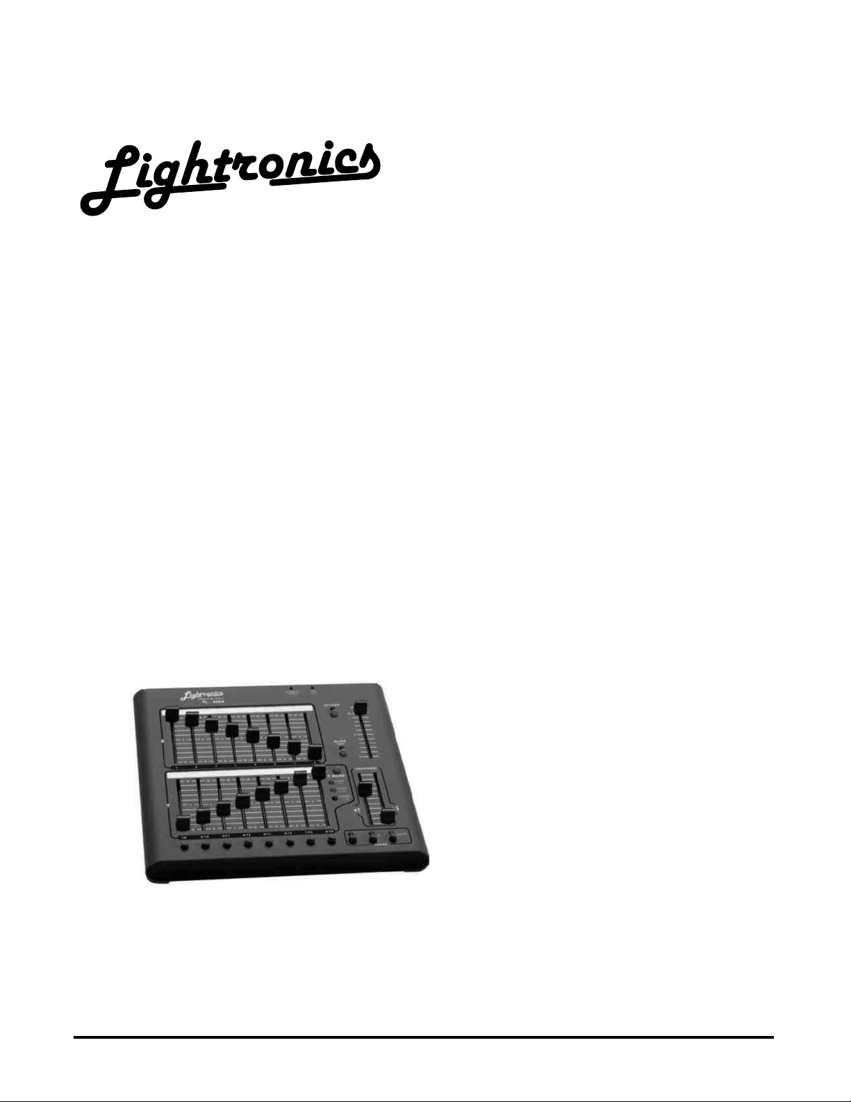
TL - 4008
MEMORY CONTROL CONSOLE
OWNERS MANUAL
VERSION 1.4
02/17/2005
www.lightronics.com
Lightronics Inc. 509 Central Drive Virginia Beach, VA 23454 757 486 3588
Page 2 of 6
TL - 4008 MEMORY CONTROL CONSOLE
Revision 1.4 OWNERS MANUAL 02/17/2005
SPECIFICATIONS
Number of channels 16 or 8 depending on mode
Operating modes 8 channels x 2 manual scenes
16 channels x 1 manual scene
8 channels and 8 recorded scenes
Scene memory 8 scenes total
Chase 2 programmable 40 step chases
Control protocol LMX-128 (multiplex)
USITT DMX-512 is optional
Other features of the TL-4008 include: grand master fader, split dipless crossfader, momentary "bump" buttons,
and blackout control. Two 40 step chases may be run simultaneously for complex patterns. Chase rate is set by
tapping the rate button at the desired rate. Scenes and chases stored in the unit are not lost when the unit is
turned off.
INSTALLATION
The TL-4008 control console should be kept away from moisture and direct sources of heat.
LMX CONNECTIONS: Connect the unit to a Lightronics (or compatible) dimmer using a multiplex control cable
with 3 pin XLR connectors. The TL-4008 is powered by the dimmer which it is connected to. It may also be
powered via an optional external power supply. The unit will operate with dimmers in both the NSI/SUNN and
Lightronics modes. All dimmers connected to the unit MUST be in the
DMX CONNECTIONS: Connect the unit to a DMX dimmer using a control cable with 5 pin XLR connectors. The
DMX-512 connection does NOT provide console power therefore an external power supply (provided with units
having DMX option) must be used.
PIN # SIGNAL NAME
LMX-128 Connector Wiring
(3 PIN FEMALE XLR)
1 Common
2
Phantom power from dimmers
Normally +15VDC
3 LMX-128 multiplex signal
CONTROLS AND INDICATORS
X Faders: Controls individual channel levels for channels 1 – 8.
Y Faders: Controls level of scenes or individual channels depending on current operating mode.
Cross Faders: Fades between X and Y row faders.
Bump Buttons: Activates associated channels at full intensity while pressed.
Chase Select: Turns chases on and off.
Chase Rate: Press three or more times at desired rate to set chase speed.
Y Mode Indicators: Indicate current operating mode of Y faders.
Y Mode Button: Selects operating mode of Y faders.
Blackout Button: Turns on and off console output from all scenes, channels, and chases.
Blackout Indicator: Lighted when blackout is active.
Grand Master: Adjusts output level of all console functions.
Record Button: Records scenes and chase patterns.
Record Indicator: Flashes when chase or scene recording is active.
www.lightronics.com
Lightronics Inc. 509 Central Drive Virginia Beach, VA 23454 757 486 3588
Output connector 3 pin female XLR connector
5 pin female XLR for DMX-512
Compatibility Multiplex protocol compatible
with other multiplex systems
Power input 13VAC or +15VDC
Optional external power supply
Dimensions 10.25"W X 9.25"D X 2.5"H
Weight 4.4 Pounds
SAME mode.
DMX-512 Connector Wiring
(5 PIN FEMALE XLR)
PIN # SIGNAL NAME
1 Common
2 DMX data -
3 DMX data +
4 Not Used
5 Not Used

Page 3 of 6
TL - 4008 MEMORY CONTROL CONSOLE
Revision 1.4 OWNERS MANUAL 02/17/2005
X
FADERS
Y
FADERS
MOMENTARY (BUMP) BUTTONS
CHASE
SELECTORS
INITIAL SETUP
CHASE RESET (Resets chases to the factory programmed defaults): Remove power from the unit. Hold down
the CHASE 1 and CHASE 2 buttons. Apply power to the unit while holding these buttons down. Continue to hold
down the buttons for approximately 5 seconds then release.
SCENE ERASE (Clears all scenes): Remove power from the unit. Hold down the RECORD button. Apply power
to the unit while holding this button down. Continue to hold down the button for approximately 5 seconds then
release.
You should check the address settings of the dimmers before proceeding with TL-4008 operati on.
OPERATING MODES
The TL-4008 is capable of operating in three different modes concerning the Y faders. Pressing the "Y MODE"
button changes the function of the Y (lower eight) faders. The selected mode is indicated by the Y mode LEDs.
The X (upper eight faders) ALWAYS control the level of channels 1 through 8.
The three operating Y modes are:
z "CH 1 - 8" In this mode both the X and Y rows of faders control channels 1 through 8. The cross fader is
used to transfer control between X and Y.
z "CH 9 - 16" In this mode the Y faders control channels 9 through 16.
z "SCENE 1 - 8" In this mode the Y faders control the intensity of 8 recorded scenes.
RECORD
GRAND
MASTER
BLACK
Y MODE
SELECT
CROSS
FADERS
CHASE
RATE
www.lightronics.com
Lightronics Inc. 509 Central Drive Virginia Beach, VA 23454 757 486 3588

Page 4 of 6
TL - 4008 MEMORY CONTROL CONSOLE
Revision 1.4 OWNERS MANUAL 02/17/2005
GENERAL OPERATION OF CONTROLS
CROSS FADERS: The cross faders provide the ability to fade between the upper (X) faders and lower (Y) faders.
The cross fade function split into two parts giving you the ability to control the level of the
upper and lower groups of faders individually. In all modes, the X cross fader must be UP to
activate the upper faders and the Y cross fader must be DOWN to activate the lower faders.
MASTER: The master level fader controls the output level of all functions of the console.
BUMP BUTTONS: These momentary buttons activate ch annels 1 through 8 while pressed. The master fader
affects the level of channels activated by the bump buttons. The bump buttons do not activate
scenes.
CHASE 1 & 2 BUTTONS: Press to select chase patterns. Chase LEDs will light when a chase is active.
CHASE RATE BUTTON: Press 3 or more times at the desired rate to set chase speed. Chase rate LED will flash
at the selected rate.
BLACKOUT BUTTON: Pressing the blackout button causes all channels, scenes and chases to go to zero
intensity. The blackout LED will light whenever the console is in blackout mode.
RECORD BUTTON: Press to record scenes and chase patterns. Record LED will light when in record mode.
RECORDING CHASES
1 Press the "RECORD" button, the record LED will flash.
2 Press the "CHASE 1" or "CHASE 2" button to select a chase to record to.
3 Use the channel faders to set the channel(s) you want to be ON in this step to full intensity.
4 Press the "RECORD" button to save the step and move to the next step.
5 Repeat steps 3 and 4 until all desired steps are recorded (up to 40 steps).
6 Press the "CHASE 1" or "CHASE 2" button to exit from the chase record mode.
CHASE PLAYBACK
1 Press the "RATE" button 3 or more times at the desired rate to set the chase speed.
2 Press "CHASE 1" button or "CHASE 2" button to turn chases on and off.
Note: Both chases may be on at the same time. If chases have a different number of steps, complex changing
patterns can be created.
RECORDING SCENES
1 Activate either the "CHAN 1– 8" or "CHAN 9-16" Y mode and create the scene to be recorded by setting the
faders to the desired levels.
2 Press "RECORD".
3 Press the bump button below the Y fader you wish to record the scene to.
Note: Scenes may also be recorded in the "SCENE 1-8" mode. This enables you to copy a scene to another or
quickly create modified versions of scenes. Recording occurs even if BLACKOUT is on or the master fader is
down.
SCENE PLAYBACK
1 Activate the "SCENE 1-8" mode.
2 Bring up a fader on the lower row (Y fader) that has had a scene recorded to it.
Note that the "Y" cross fader must be DOWN to use the lower(Y) faders.
www.lightronics.com
Lightronics Inc. 509 Central Drive Virginia Beach, VA 23454 757 486 3588

Page 5 of 6
TL - 4008 MEMORY CONTROL CONSOLE
Revision 1.4 OWNERS MANUAL 02/17/2005
DMX OPERATION
If the DMX option is installed in the TL-4008 then it will transmit both DMX and LMX signals simultaneously.
The DMX-512 connection does NOT provide console power therefore an external power supply (provided with
units having DMX option) must be used.
QUICK START INSTRUCTIONS
The bottom cover of the TL-4008 contains brief instructions for using scenes and chases. The instructions are not
intended as a substitute for this manual and should be viewed as "reminders" for operators who are already
familiar with TL-4008 operation.
MAINTENANCE AND REPAIR
TROUBLESHOOTING
Check that the multiplex cable is not defective.
To simplify troubleshooting - reset the unit to provide a known set of conditions.
Make sure the dimmer address switches are set to the desired channels.
OWNER MAINTENANCE
The best way to prolong the life of your TL-4008 is to keep it dry, cool, clean and covered when not in use.
The unit exterior may be cleaned using a soft cloth dampened with a mild detergent/water mixture or a mild spray-
on type cleaner. DO NOT SPRAY ANY LIQUID directly on the unit. DO NOT IMMERSE the unit in any liquid or
allow liquid to get into the controls. DO NOT USE any solvent based or abrasive cleaners on the unit.
The faders are not cleanable. If you use a cleaner in them – it will remove the lubrication from the sliding
surfaces. Once this happens it is not possible to re-lubricate them.
The white strips above the faders are not covered by the TL-4008 warranty. If you mark on them with any
permanent ink, paint etc. it is likely that you will be unable to remove the markings without damaging the strips.
There are no user serviceable parts in the unit. Service by other than Lightronics authorized agents will void your
warranty.
EXTERNAL POWER SUPPLY INFORMATION
The TL-4008 may be powered by an external supply with the following specifications:
Output Voltage: 13 to 25 Volts AC or DC
Output Current: 400 Milliamps
Connector: 2.1mm female connector
NOTE: If a DC Supply is used – the center pin must be the NEGATIVE voltage.
OPERATING AND MAINTENANCE ASSISTANCE
Dealer and Lightronics Factory personnel can help you with operation or maintenance problems. Please read the
applicable parts of this manual before calling for assistance.
If service is required - contact the dealer from whom you purchased the unit or contact Lightronics, Service
Dept., 509 Central Drive, Virginia Beach, VA 23454 TEL: (757) 486-3588.
www.lightronics.com
Lightronics Inc. 509 Central Drive Virginia Beach, VA 23454 757 486 3588

All Lightronics products are warranted for a period of TWO/FIVE YEARS from the date of
purchase against defects in materials and workmanship.
This warranty is subject to the following restrictions and conditions:
A) If service is required, you may be asked to provide proof of purchase from an authorized
Lightronics dealer.
B) The FIVE YEAR WARRANTY is only valid if the warranty card is returned to Lightronics
accompanied with a copy of the original receipt of purchase within 30 DAYS of the purchase
date, if not then the TWO YEAR WARRANTY applies. Warranty is valid only for the original
purchaser of the unit.
C) This warranty does not apply to damage resulting from abuse, misuse, accidents, shipping,
and repairs or modifications by anyone other than an authorized Lightronics service
representative.
D) This warranty is void if the serial number is removed, altered or defaced.
E) This warranty does not cover loss or damage, direct or indirect arising from the use or
inability to use this product.
F) Lightronics reserves the right to make any changes, modifications, or updates as deemed
appropriate by Lightronics to products returned for service. Such changes may be made
without prior notification to the user and without incurring any responsibility or liability for
modifications or changes to equipment previously supplied. Lightronics is not responsible for
supplying new equipment in accordance with any earlier specifications.
G) This warranty is the only warranty either expressed, implied, or statutory, upon which the
equipment is purchased. No representatives, dealers or any of their agents are authorized to
make any warranties, guarantees, or representations other than expressly stated herein.
H) This warranty does not cover the cost of shipping products to or from Lightronics for
service.
I) Lightronics Inc. reserves the right to make changes as deemed necessary to this warranty
without prior notification.
WARRANTY
Lightronics Inc. 509 Central Drive Virginia Beach, VA 23454 20050125
 Loading...