

Page 1
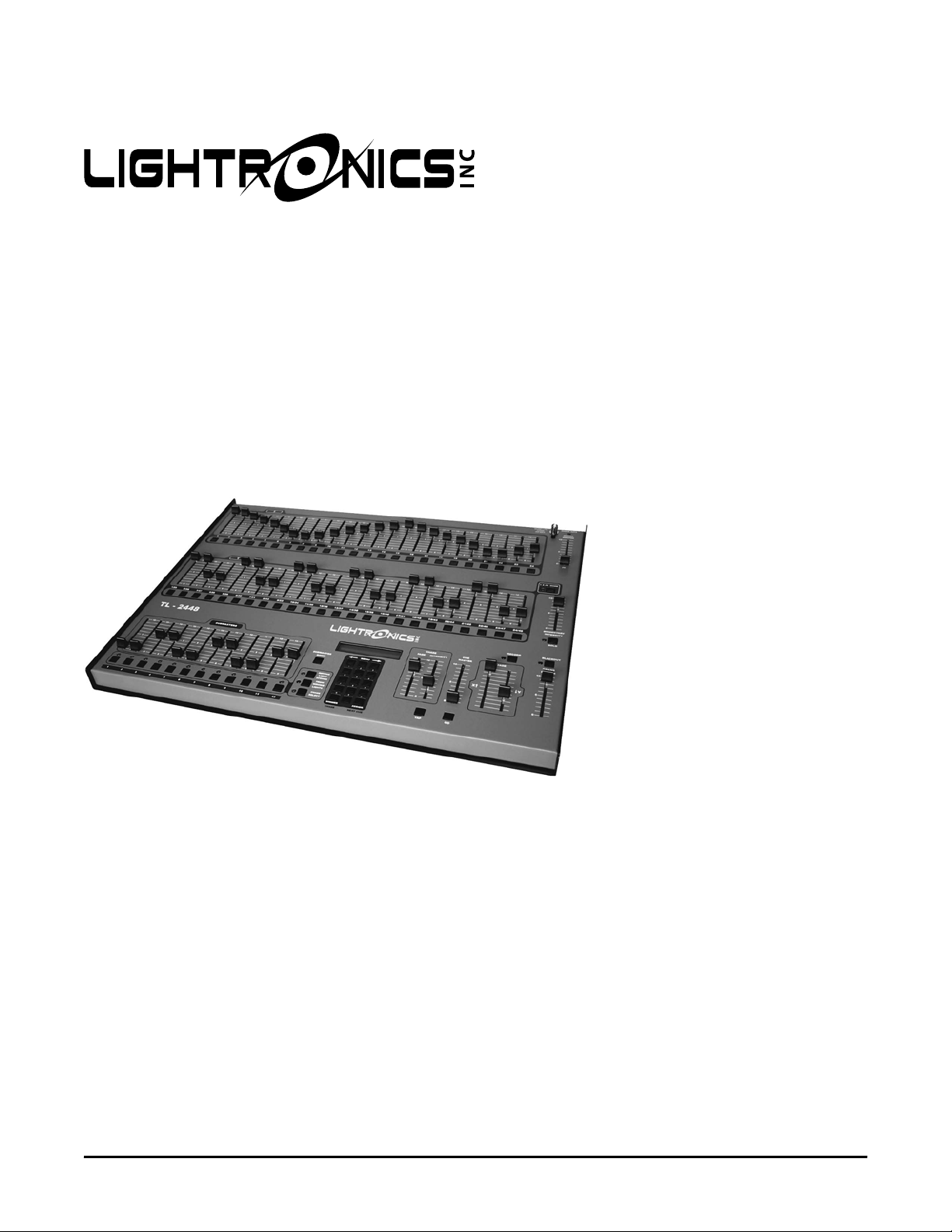
TL - 2448
LIGHTING CONTROL CONSOLE
OWNERS MANUAL
Revision 0.6
12/27/2007
www.lightronics.com
Lightronics Inc. 509 Central Drive Virginia Beach, VA 23454 757 486 3588
Page 2
Page 2 of 18
TL - 2448 LIGHTING CONTROLLER
Version 0.6 OWNERS MANUAL 12/27/2007
TABLE OF CONTENTS
PRODUCT DESCRIPTION 3
DIMENSIONS AND WEIGHT 3
INSTALLATION 3
POWER REQUIREMENTS 3
SIGNAL CONNECTIONS 3
SIGNAL WIRING CONNECTIONS 3
WORK LIGHT 3
CONTROLS AND INDICATORS 4
THE LCD DISPLAY 5
THE MENU SYSTEM 5
SETUP AND PRELIMINARY OPERATIONS 6
CONSOLE RESET 6
CHANNEL ASSIGNMENTS (PATCHING) 6
DEFAULT CHANNEL ASSIGNMENTS 6
PATCH PAGES 6
TO CHANGE THE CURRENT PATCH PAGE 6
ASSIGNING CURRENT PATCH PAGE CHANNELS 6
TO COPY A PATCH PAGE 7
TO RESET THE CURRENT PATCH PAGE 7
MANUAL OPERATION 7
MODES OF OPERATION 7
SCENE RECORDING AND PLAYBACK 8
RECORDING A SCENE 8
SCENE PLAYBACK 8
CHASE FUNCTIONS 8
CHASE RECORDING 9
ASSIGNING SCENES TO CHASE STEPS 9
CHASE PLAYBACK 10
USING CUE LISTS 10
CUE LIST RECORDING 10
INITIAL CUE LIST ASSIGNMENTS 10
VIEWING AND EDITING THE CUE LIST 11
TO ASSIGN SCENES TO A CUE 11
CUE LIST PLAYBACK 11
CONTROLLING MOVING LIGHTS 12
SOFT-PATCHING MOVING LIGHT CHANNELS 12
DEFAULT MOVING LIGHT CHANNELS 12
CREATING MOVING LIGHT SCENES 13
SETTING BASIC SCENE CONDITIONS 13
RECORDING THE SCENE 13
APPLYING SCENE FADE CONTROLS 14
CHANNEL CONFIGURATIONS 14
CONFIG - SETTING THE CHANNEL CONFIGURATION 14
DEFAULT FADE 15
FADE RATE 15
ACTIVATING MOVING LIGHT SCENES 15
MANUAL SCENE ACTIVATION 15
MOVING LIGHT SCENES IN CUE'S OR CHASES 15
TL-2448 WIRELESS OPTION 15
MAINTENANCE AND REPAIR 17
OWNER MAINTENANCE 17
TROUBLESHOOTING 17
OPERATING AND MAINTENANCE ASSISTANCE 17
WARRANTY 18
www.lightronics.com
Lightronics Inc. 509 Central Drive Virginia Beach, VA 23454 757 486 3588
Page 3
Page 3 of 18
TL - 2448 LIGHTING CONTROLLER
Version 0.6 OWNERS MANUAL 12/27/2007
PRODUCT DESCRIPTION
The TL-2448 is a multi-application lighting control console. The unit provides both LMX-128 (multiplex) and DMX512 output protocols simultaneously. This console will store 600 conventional scenes which can be cued with
control of fade times. The cue list may hold up to 600 scenes. There are 2 patch pages for reassigning outp ut
channels. Thirty six chase sequences may be created and stored by the operator. Each of these may have 40
steps. Dedicated moving lights support is included for up to 8 moving light fixtures with up to 12 channels per
fixture. 600 additional scenes are available for moving light control.
DIMENSIONS AND WEIGHT
The TL-2448 measures Aprox. 23” wide X 18” deep X 2.5” high. The unit weight is 23 pounds.
INSTALLATION
POWER REQUIREMENTS
The TL-2448 is powered by a 120VAC, 50/60 Hz. A ON/OFF switch is located along the back edge of the unit.
The power consumption is 20 Watts.
SIGNAL CONNECTIONS
Output signal connectors for the LMX-128 and DMX-512 protocols are provided along the rear edge of the unit.
MIDI connections are also located along the rear edge. Three wire shielded microphone type cable may be used
for the LMX-128 signal. Connections for DMX-512 are via the 5 pin female XLR connector. DMX requires a high
grade, low capacitance cable ( 25pf per foot or less). DMX control cable systems should be terminated by a 130
Ohm, 1/4 watt resistor at the last device on the DMX chain. The terminator connects between pins 2 and 3 on a
DMX bus.
SIGNAL WIRING CONNECTIONS
LMX-128 3 Pin, Female XLR Connector DMX-512 5 Pin Female XLR Connector
PIN NUMBER SIGNAL
1 Common or Signal Ground
2 Not Used
3 Multiplexed signal
WORK LIGHT
The “BNC” coaxial connector near the upper right corner of the unit will accommodate a 12vdc flexible shaft lamp
to assist operating the console in dark areas. The maximum power available at this connector is 5 Watts.
www.lightronics.com
Lightronics Inc. 509 Central Drive Virginia Beach, VA 23454 757 486 3588
PIN NUMBER SIGNAL
1 DMX Common
2 DMX Data 3 DMX Data +
4 Not Used
5 Not Used
Page 4
Page 4 of 18
g
TL - 2448 LIGHTING CONTROLLER
Version 0.6 OWNERS MANUAL 12/27/2007
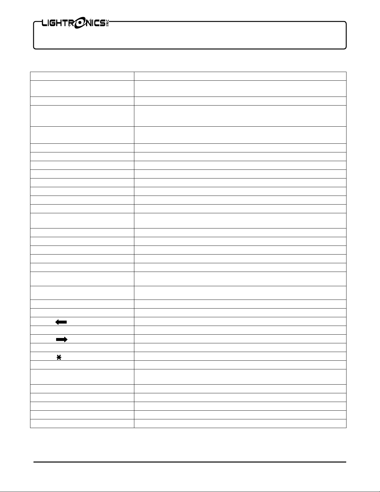
CONTROLS AND INDICATORS
X Faders Controls intensity of channels 1 - 24
Y Faders
SUBMASTERS Faders Activates prestored scenes.
HOUSE MASTER Fader
GRAND MASTER Fader
X and Y Cross Fader Pair Transfers control between upper and lower channel faders.
MOMENTARY INTENSITY Fader Controls the intensity level of the momentary (bump) buttons.
CUE MASTER Fader Controls the overall intensity of scenes activated via the cue list.
Chase FADE Fader Controls the rate at which chase steps fade in and out.
Chase INTENSITY Fader Controls the intensity of the chase patterns.
Momentary (BUMP) Buttons Activates the associated channel while depressed.
Submaster Momentary Buttons Activates the associated scene while depressed.
1 x 48 MODE Button and Indicator Controls whether lower (Y) faders will act as channels 1- 24 or 25 – 48.
SOLO Button and Indicator
BLACKOUT Button and Indicator Turns off all channels, scenes and chase patterns.
RECORD Button and Indicator Used to save scenes, chases, and cues into the TL-2448 memory.
GO Button Causes Cue to advance to the next scene in the list.
TAP Button Controls the chase step rate.
SUBMASTER BANK Button Used to set the current scene bank.
MOVING LIGHT SCENES Button
and Indicator
PRGM MOVING LIGHTS Button
and Indicator
CHASE SELECT Button and LED Enables submaster momentary buttons as chase 1 – 12 sel ection.
Keypad Buttons Used to enter various patch, chase, and cue list selections.
(Left Arrow) Used with menu system.
MENU Activates menu system and executes menu selections.
(Right Arrow ) Used with menu system. Also selects current patch page.
Number Keys Used to enter and edit various setup parameters.
(DIMMER / CHASE) Used with keypad to enter various parameters.
# (ASSIGN / NEXT CUE)
LCD Display
POWER Indicator Indicates unit is on and flashes at the current chase rate.
WORK LIGHT Connector Used for a 12vdc lamp.
Controls intensity of channels 1 – 24. Controls intensity of channels 25 –
48 in 1 x 48 mode
Console channel 99. Controls any dimmer channel assigned to this
number. The fader acts independently of all other console functions
includin
the GRAND MASTER fader.
Master override control for all channels and scenes. Does not affect
HOUSE MASTER or chase levels.
Causes bump button to blackout all channels except the channel
associated with the button pushed.
Activates moving light scenes.
Controls moving light set up.
Used to enter various parameters.
Shows status of various functions and is used with the menu system to set
the parameters of the console operation.
www.lightronics.com
Lightronics Inc. 509 Central Drive Virginia Beach, VA 23454 757 486 3588
Page 5
Page 5 of 18
Y
TL - 2448 LIGHTING CONTROLLER
Version 0.6 OWNERS MANUAL 12/27/2007
THE LCD DISPLAY
The LCD display is used to show the current status of various functions. During normal operation it indicates the
current scene bank number, the current and next cue number , and the current chase number including the
current chase step number. This is called the STATUS DISPLAY. The LCD is also a menu system which will be
described in detail further on in this manual.
CURRENT SCENE BANK
CURRENT CHASE : STEP
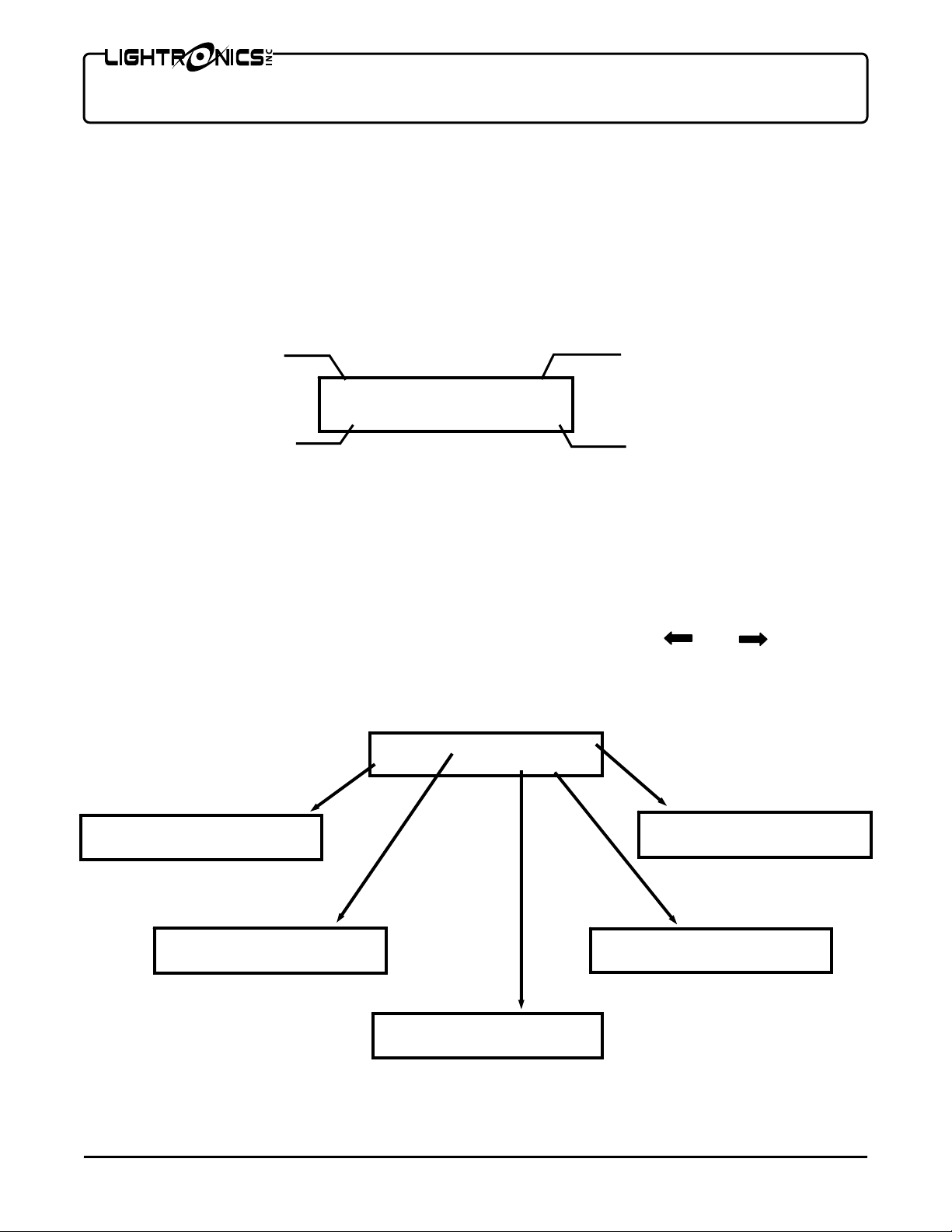
THE MENU SYSTEM
The menu system controls the features and configuration settings for the TL-2448. It is activated by pushing the
MENU button on the keypad. The TL - 2448 menu structure below. Each of the main menu choices leads to a
more detailed submenu to control that specific feature. To activate a menu, use the and keys to move
between the selections on the main menu. When your choice is blinking, push MENU to select it. Use the same
process to select submenus further down in the structure.
MOVING LIGHTS MENU
EXIT FADE RATE
CONFIG DEFAULT FADE
CHASER MENU
ST01 CS01-01 MS01-01
Chase-01 NextItem
www.lightronics.com
Lightronics Inc. 509 Central Drive Virginia Beach, VA 23454 757 486 3588
STATUS DISPLA
BNKC-01 Q-001
CHASE-01:01 N-002
MAIN MENU
EXIT CHASER Q-EDIT
MLIGHT SFTPTCH SETUP
SOFTPATCH MENU
EXIT PAGE=1
REPATCH
CURRENT CUE
NEXT CUE
Q EDIT MENU
Q001 CS01-1 MS01-01
FO001 FI001 NextItem
SETUP MENU
EXIT
ERASEall
Page 6
Page 6 of 18
TL - 2448 LIGHTING CONTROLLER
Version 0.6 OWNERS MANUAL 12/27/2007
SETUP AND PRELIMINARY OPERATION
CONSOLE RESET
The TL-2448 may be cleared or reset using the menu system. It is recommended that the reset procedure be
used anytime you begin to set the board up for a new application. This is also a good idea when having
operational difficulties since it will configure the unit to a known set of conditions. If you have scenes, cues or
chases stored in the unit, be sure that they are written down before you reset the board since they will be lost
once the reset is performed.
You can reset the console by using the SETUP menu. Executing the ERASEALL submenu function will cause
the following actions to occur:
A one to one channel assignment scheme will be invoked for patch page 1.
Patch page 2 will be completely cleared .
All cues will be set to point to factory default banks/scenes.
Conventional and moving light scenes will be cleared.
Chase pattern 1 will be set to point to the factory default bank/scene. Chases 2 – 36 will be cleared.
CHANNEL ASSIGNMENTS (PATCHING)
DEFAULT CHANNEL ASSIGNMENTS
Execution of an ERASEALL on the console results in a 1 to 1 patch for dimmer channels 1 - 48. The pattern is
repeated beginning at dimmer channel 49 (It is assigned to console channel 1 again). The repeat co ntinues up to
dimmer channel 256. Beginning at dimmer channel 257 - assignments are made to moving light fixture channels.
The moving light channels may be re-assigned to conventional dimmer channels.
You can assign console channels to dimmer channels other than a 1 to 1 corresponde nce. For instance you may
want to have the lights connected to dimmer channels 1 and 2 assigned to console fader 3. (You can have
several dimmer channels patched to a single console fader but you cannot assign a dimmer channel to more than
1 console channel at a time.) This channel assignment or “patch” information can be saved in the console as a
“patch page”.
PATCH PAGES
The TL-2448 contains 2 patch pages. In situations where the console is used for different applications, multiple
patch pages can save time that would be spent re-patching each channel for a given application. The current
patch page may be toggled between the two pages by using the MENU system.
TO CHANGE THE CURRENT PATCH PAGE
1. Enter the SFTPTCH submenu and push to select the PAGE= n choice. It will begin flashing.
2. Push MENU to toggle the choice between patch pages 1 and 2.
ASSIGNING CURRENT PATCH PAGE CHANNELS
Channel assignments are always applied only to the currently selected patch page.
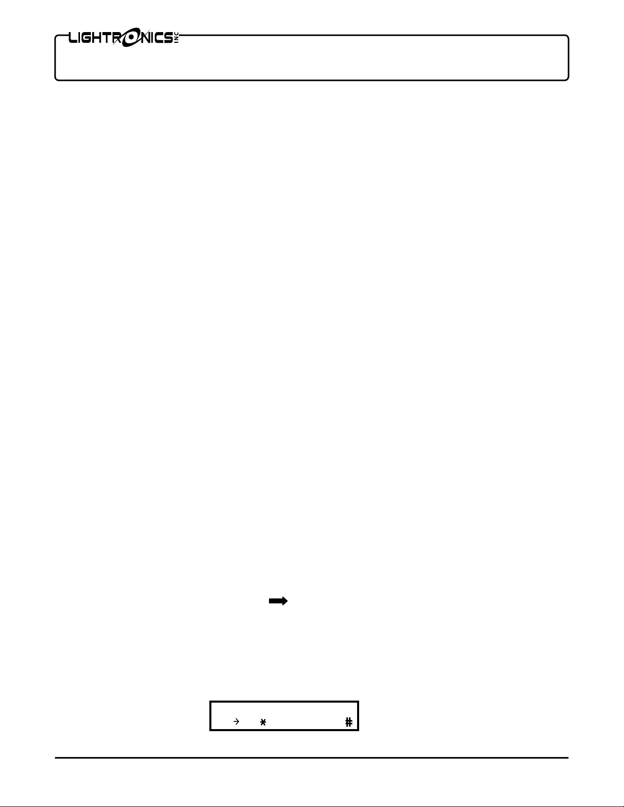
Enter the SFTPTCH menu and select REPATCH. The following subm enu will be shown:
www.lightronics.com
Lightronics Inc. 509 Central Drive Virginia Beach, VA 23454 757 486 3588
Patch Dimmers 0000
DIM 000 CON= 00
Page 7

Page 7 of 18
TL - 2448 LIGHTING CONTROLLER
Version 0.6 OWNERS MANUAL 12/27/2007
Enter a dimmer channel number on the keypad and push
side of the lower row as a dimmer channel selection. Now enter a console channel number as a two digit number
on the keypad and push #. This number now appears on the right side of the lower display row and is assigned
to the dimmer channel shown on the left. You can continue this sequence for as many channel assignments as
necessary. You can use the and keys while assigning channels to cycle through the dimmer channel
assignments and observe or change the assignments as needed. It is possible to enter fou r d igit numbers for the
console channel. If you do so - the assignment will apply to moving light fixtures. See the section of this manual
which applies to moving light control.
TO COPY A PATCH PAGE
1. Enter the SFTPTCH menu and select COPY. The following submenu will be shown:
COPY SOFTPATCH TO –2
MENU to Abort
2. Enter the number (1 or 2) to select where the copy destination will be.
3. Push the
# key to execute the copy operation or push MENU to return to normal operation without
activating the copy function.
TO RESET THE CURRENT PATCH PAGE
Enter the SFTPTCH menu and select RESET. The following submenu will be shown:
EXIT CLEAR
PATCH 1to1
The CLEAR selection will DE-ASSIGN all channels. Console channels are not assigned to any dimmer channels.
This condition is useful as a starting point for assigning channels since it provides a known set of conditions. This
function affects only the current patch page.
The PATCH 1 to 1 selection assigns a 1 to 1 patch between dimmer and console channels as described in the
DEFAULT CHANNEL ASSIGNMENTS section of this manual. The assignment is only for the current patch page.
MANUAL OPERATION
MODES OF OPERATION
Manual operation of the TL-2448 includes two operating modes. These are referred to as the 2 X 24 and 1 X 48
mode. The mode may be switched by the 1 X 48 button located on the right side (slightly above center) of the
console. The associated LED indicator is lighted in the 1 X 48 mode.
The TL2448 operates as follows in the two modes described above:
2 X 24 MODE: In this mode only channels 1 – 24 are accessible via the faders. You can create a manual scene
with the X faders (upper row) and another with the Y faders (lower row). Once scenes are created you can use
the X/Y CROSSFADE pair to control which row is active. The upper row of momentary buttons will flash the
corresponding channel.
1 X 48 MODE: In this mode all 48 channels are accessible via the faders. The lower row is channels 25 – 48.
This mode us useful for creating and saving preset scenes.
www.lightronics.com
Lightronics Inc. 509 Central Drive Virginia Beach, VA 23454 757 486 3588
. The number you entered now appears on the left
Page 8

Page 8 of 18
TL - 2448 LIGHTING CONTROLLER
Version 0.6 OWNERS MANUAL 12/27/2007
SCENE RECORDING AND PLAYBACK
Scenes in the TL-2448 are organized into 50 banks of 12 scenes each. You can create and store sce nes using
either the 2 x 24 mode or the 1 x 48 mode. All scenes are capable of recording all 48 channels. Scene banks are
selected by the SUBMASTER BANK button. The current bank is shown on the LCD STATUS DISPLAY. Once
scenes are recorded they may be played back via the SUBMASTER faders or their associated momentary
buttons. Stored scenes are retained until overwritten or cleared. Scenes ARE NOT LOST when the console is
turned off. Scenes ARE cleared by the ERASE ALL function in the SETUP menu.
RECORDING A SCENE
Make the desired bank current by pushing the SUBMASTER BANK button until the desired bank is shown on
the LCD display or enter the desired bank number on the keypad and push the SUBMASTER BANK button.
1. Create the scene using the faders.
2. Push RECORD. (The LED indicators under the submaster faders will flash.)
3. Push the momentary button associated with the fader you want the scene recorded to.
The scene is now available to be activated anytime that bank is currently selected.
SCENE PLAYBACK
1. Make the desired bank current by pushing the SUBMASTER BANK button until the desired bank is shown on
the LCD display.
2. You can activate the scene by its submaster fader. The scene will fade in and out as you raise and lower the
fader. You can also activate the scene with the associated momentary button. In this case the scene will
instantly come on at its recorded intensity and remain on until you release the momentary button.
Scenes are subject to the setting of the GRAND MASTER fader and are affected by BLACKOUT.
CHASE FUNCTIONS
The TL-2448 will record and playback 36 chase patterns. Each pattern is user programmable and may contain up
to 40 steps. The overall brightness of a running chase is controlled by using the CHASE INTENSITY fader.
The rate of chase step advance (chase rate) is user controllable. Chase rate is controlled by pushing the TAP
button at the desired rate three or more times. The maximum chase step time is 999 seconds. The fade time of
the chase steps is adjustable from 0–100% of the step duration. Chase fade time is controlled by the CHASE
FADE fader.
The first 12 chase patterns are accessible for playback directly from the submaster momentary buttons if you first
push the CHASE SELECT button. All 36 of the chase patterns are available via the keypad. The current chase
rate and chase fade time is applied to all chase patterns. Chase patterns are affected by the GRAND MASTER
fader and BLACKOUT. Chase operation is exclusive (only 1 chase may be active at a time).
www.lightronics.com
Lightronics Inc. 509 Central Drive Virginia Beach, VA 23454 757 486 3588
Page 9

Page 9 of 18
TL - 2448 LIGHTING CONTROLLER
Version 0.6 OWNERS MANUAL 12/27/2007
CHASE RECORDING
Chase steps consist of scenes which have been previously recorded. When you record a chase step you are
telling the TL-2448 to recall a specific scene from a specific bank.
A chase must be active before it can be programmed from the chaser menu. You can do this from the normal
STATUS DISPLAY. Enter the chase number on the keypad and push
first 12 chase patterns, you can also make it active by pushing the CHASE SELECT button. The LED
indicators under the submaster faders will flash. Push a submaster momentary button to activate any one of the
12 chase patterns. Note that in either case, the lower left of the display shows the currently active chase and step
number.
Chase pattern recording is done from the CHASER menu which is accessed from the main menu after you have
made the chase active. You can also look at and change the existing chaser assignments from this menu.
CHASER MENU
ST01 CS01-01 MS01-01
Chase-01 NextItem
The upper display row shows the current chase step number, the conventional bank-scene number assigned to
the step, and the moving light bank-scene number assigned to the step. The lower left of the display shows the
current chase number. The current chase number cannot be changed from this menu.
The bottom right of the CHASER menu indicates how the Í and Î buttons on the keypad may be used inside
the CHASER menu. When “NextItem” is visible, the Í and Î buttons will move you to the next or previous
menu item. You may change this action by pushing the MENU button. If you do this the display will show
“ÍAlterΔ and you can use the Í and Î buttons to alter the value (up or down) of the currently flashing menu
item. For instance – when the step number is flashing and “ÍAlterΔ is displayed you can look at the next or
previous step assignments by pushing Í or Î.
ASSIGNING SCENES TO CHASE STEPS:
The steps below are used if the menu shows “NextItem” in the lower left display corner.
1. Push Í or Î until the step number flashes. Enter the step number on the keypad and push #.
2. Push Î to advance to the conventional scene bank number. Enter the bank number and push #.
3. Push Î to advance to the conventional scene number. Enter the scene number and push #.
If you want to include a moving light scene in the chase step:
4. Push Î to advance to the moving light scene bank number. Enter the bank number and push #.
5. Push Î to advance to the moving light scene number. Enter the scene number and push #.
To end the chase recording process push Í or
Î (while”NextItem” is visible) until a flashing “EXIT” appears in
the display lower right corner. Then push MENU.
www.lightronics.com
Lightronics Inc. 509 Central Drive Virginia Beach, VA 23454 757 486 3588
. If you want to program one of the
Page 10

Page 10 of 18
TL - 2448 LIGHTING CONTROLLER
Version 0.6 OWNERS MANUAL 12/27/2007
CHASE PLAYBACK
The current chase pattern number and step number are always shown on the STATUS DISPLAY lower left.
The first 12 chase patterns can be quickly activated by pushing the CHASE SELECT button. The LED indicators
under the submaster faders will flash. Push a submaster momentary button to activate any of the 12 chase
patterns.
To activate ANY chase pattern: Enter its number on the keypad – then push the key.
Adjust the brightness of the chase using the CHASE INTENSITY fader.
Adjust the chase rate with the TAP button and adjust the chase fade time using the CHASE FADE fader. The
chase fade will adjust the fade time to anywhere between 0 and 100% of the step time.
It is not necessary to set these chase controls before activating a chase but if you set them first – the chase will
begin at your approximate desired settings.
USING CUE LISTS
After you have created and saved scenes in the TL-2448, you can put them into a scene cue list. Once the cue
list has been created, you can “play” the list by pushing the GO button. Pushing this button causes the current
cue scene to fade out and the next scene to fade in. Each entry in the cue list contains the bank number of a
scene, the scene number within that bank, a “fade in” time , and a “fade out” time. The “fade out” time is the
number of seconds the PREVIOUS cue scene will take to fade out as the current cue scene fades in. You can
adjust both of these times to obtain various effects. Fade times can range from 0 to 999 seconds. The overall
brightness of cues is controlled by the CUE MASTER fader. Cues are affected by the BLACKOUT function
and the GRAND MASTER fader. Cue number 0 is reserved as a blackout and is not programmable.
The LCD STATUS DISPLAY always shows the current cue number in the upper right section and the next cue
number in the lower right. Cues normally proceed in a sequential manner (cue 2 follows cue 1… etc.). You can
alter the order of cue playback using the keypad. If you enter a cue number and push ENTER (#), the display
will indicate your entry as the next cue to be activated. When you push GO – this cue will fade in.
CUE LIST RECORDING
INITIAL CUE LIST ASSIGNMENTS
The TL-2448 is provided with factory supplied cue list assignments (default cue list). This initial assignment will
be invoked any time the ERASE ALL function is executed from the SETUP menu. The default cue list
assignments are arranged in 12 groups of 48 cues each. The first group is assigned as follows:
CUE BANK SCENE
01 – 12 1 1 thru 12
13 – 24 2 1 thru 12
25 – 36 3 1 thru 12
37 – 48 4 1 thru 12
This assignment is repeated for the next group (beginning at cue 49). The result is that cue 49 will have the same
assignments as cue 1. This sequence is repeated for each following group of 48 cues.
www.lightronics.com
Lightronics Inc. 509 Central Drive Virginia Beach, VA 23454 757 486 3588
Page 11

Page 11 of 18
TL - 2448 LIGHTING CONTROLLER
Version 0.6 OWNERS MANUAL 12/27/2007
VIEWING AND EDITING THE CUE LIST
You can look at and change the current cue assignments from the Q-EDIT menu which is accessed by selecting
it from the main menu. The menu is shown here.
The cue number will be shown flashing in the upper left menu corner. The rest of the menu will show the settings
for that cue. The top center shows the bank and scene number of the conventional scene for that cue. The top
right shows the same information for the moving light scene for that cue. The bottom row shows the fade out and
fade in times (seconds) for the cue.
The bottom right of the Q-Edit menu indicates how the Í and Î buttons on the keypad may be used inside the
Q-EDIT menu. When “NextItem” is visible, the Í and Î buttons will move you to the next or previous menu
item. You may change this action by pushing the MENU button. If you do this the display will show “ÍAlterΔ
and you can use the Í and Î buttons to alter the value (up or down) of the currently flashing menu item. For
instance – when the cue number is flashing and “ÍAlterΔ is displayed you can look at the next or previou s cu e
assignments by pushing Í or Î. This a quick method to review cue settings.
TO ASSIGN SCENES TO A CUE:
The steps below are used if the menu shows “NextItem” in the lower left display corner.
1. Push Í or Î until the cue number flashes. Enter a cue number on the keypad and push #.
2. Push Î to advance to the conventional scene bank number. Enter the bank number and push #.
3. Push Î to advance to the conventional scene number. Enter the scene number and push #.
If you want to include a moving light scene in the cue:
4. Push Î to advance to the moving light scene bank number. Enter the bank number and push #.
5. Push Î to advance to the moving light scene number. Enter the scene number and push #.
6. Push Î to advance to fade out time. Enter the fadeout time on the keypad and push #.
7. Push Î to advance to fade in time. Enter the fade in time on the keypad and push
You can sequentially scan through the cues in consecutive order when the cue number is flashing and “ÍAlterΔ
is displayed, by using the Í and Î buttons.
To end the cue recording process Push Í or Î (while ”NextItem” is visible) until flashing “EXIT” appears in the
display lower right corner. Then push MENU.
CUE LIST PLAYBACK
Playing the cue list is a simple matter of pushing the GO button. The GO button activates the next consecutive
cue. The current cue’s scene will fade out and the scene for the next cue will fade in. The normal STATUS
DISPLAY always shows the current cue and the next cue to keep you aware of the cue sequence. The overall
intensity of cue list scenes is controlled by the CUE MASTER fader.
You can change the order of cue list playback during normal operation by using the keypad. To choose a specific
cue to be activated – enter its number on the keypad and push #. This assigns that cue to be next and its
number will show in the lower right corner of the STATUS DISPLAY. When you push GO - This cue will be
invoked.
www.lightronics.com
Lightronics Inc. 509 Central Drive Virginia Beach, VA 23454 757 486 3588
Q001 CS01-1 MS01-01
FO001 FI001 NextItem
#.
Page 12

Page 12 of 18
TL - 2448 LIGHTING CONTROLLER
Version 0.6 OWNERS MANUAL 12/27/2007
There is a cue number 0 which is not programmable. This cue contains a blackout. You can invoke this cue
during normal operation by using the keypad as described above.
CONTROLLING MOVING LIGHTS
The TL-2448 Console has a dedicated set of functions to control moving lights. Moving light fixtures and
conventional lighting may be operated simultaneously. There are provisions to control up to 8 moving light
fixtures with 12 channels for each fixture. The TL-2448 has 600 scenes (arranged as 50 banks of 12 scenes
each) which are dedicated moving light scenes. Moving light scenes may be used in the cue list and chases.
Moving light control using the TL-2448 is designed to operate on a "scene" basis. The overall approach to
setting up a moving light consists of:
1. Setting the DMX address on the moving light fixture to the desired DMX start channel.
2. Soft-patching a set of TL-2448 console channels to correspond to the desired fixture/channel block.
3. Creating and storing as many basic scenes as desired to operate the fixture.
4. Setting the fade controls for the scenes.
The scenes you create can then be activated from the TL-2448 SUBMASTER momentary buttons, entered into
the cue list, or included in chases.
SOFT-PATCHING MOVING LIGHT CHANNELS
DEFAULT MOVING LIGHT CHANNEL ASSIGNMENTS
The TL-2448 is provided with default channel address assignments. You normally will not have to change these
assignments for moving light control.
The default patch configuration for the TL-2448 assigns dimmer channels 1 - 256 as conventional lighting
channels. Dimmer channel 257 is assigned to moving light Fixture 1/Channel 1. Channel 258 is Fixture
1/Channel 2. The remaining 10 channels of Fixture 1 are assigned consecutively . The next available dimmer
channel (269) is assigned to Fixture 2/Channel 1. The assignments then proceed consecutively through Fixture
2/Channel 12. These assignments continue through Fixture 8/Channel 12. A table of default channel
assignments is shown below.
Fixture #
1. Proceed to the SFTPTCH menu and select REPATCH. The menu shows the current channel assignments.
2. Select a dimmer channel (1 - 512). Enter the number on the keypad and push the key OR use the and
keys to cycle through the dimmer channels. The dimmer channel will be shown on the display lower left and
it's assigned console channel will be shown on the lower right.
www.lightronics.com
Lightronics Inc. 509 Central Drive Virginia Beach, VA 23454 757 486 3588
DEFAULT MOVING LIGHT CHANNELS
DMX Start Channel Fixture #
DMX Start Channel
1 257 5 305
2 269 6 317
3 281 7 329
4 293 8 341
Patch Dimmers 0000
DIM 000 CON= 00
Page 13

Page 13 of 18
TL - 2448 LIGHTING CONTROLLER
Version 0.6 OWNERS MANUAL 12/27/2007
3. To change the assigned console channel, enter a valid console channel number and push the # key. If you
enter a 2 digit number 1 - 48 (or 99, for the house master) then your entry will be accepted as a conventional
lighting channel. If you enter a 4 digit number then the entry will be assigned as a moving light fixture and
channel. The left 2 digits are 1 - 8 for the fixture number and the right 2 digits are 1 - 12 for the channel
number within the fixture.
As an example: An assignment of dimmer channel 259 to channel 3 of moving light fixture 2 will appear on the
display as show here.
CREATING MOVING LIGHT SCENES
SETTING BASIC SCENE CONDITIONS
1. To create a moving light scene you must first select the fixture: Push PROGRAM MOVING LIGHTS then
push the SUBMASTER momentary button corresponding to the fixture number (1 - 8). Fixture number 1 is
on the left. You can select more than one fixture at a time by selecting more than one SUBMASTER
momentary button.
2. At this point you can control the moving light fixture from the SUBMASTER faders. Each of the faders
controls one of the fixture functions. For instance fader 1 may control pan and fader 2 control tilt. The
function of each fader depends on the particular fixture model so you will need to consult the manual for the
fixture to determine which channel controls which fixture function.
USE CAUTION WHEN MOVING FADERS. YOU COULD CAUSE THE FIXTURE TO MOVE IN UNEXPECTED
WAYS IF YOU ARE NOT FAMILIAR WITH ITS OPERATION. THIS CAN BE A DANGER TO PERSONS NEAR
THE FIXTURE. IT MAY ALSO BE POSSIBLE TO DAMAGE THE FIXTURE.
RECORDING THE SCENE
Once you have adjusted all the fixture functions the moving light scene is ready for recording. It can be stored in
one of the 12 scenes available in any of the moving light scene banks (1-50). To record the scene:
1. The display shows the current moving light scene bank in the upper left section as BNKM-nn, where nn is the
bank number. Select the desired bank by pushing the SUBMASTER BANK button (which will cycle through
the banks) OR enter the bank number on the keypad and then push the SUBMASTER BANK button.
2. Push the RECORD button. The RECORD light and 12 SUBMASTER momentary lights will flash.
3. Push the SUBMASTER momentary button that corresponds to the scene number (1-12) where you want the
scene stored.
At this point the scene is stored in the selected bank and scene number with the DEFAULT scene fade rate
applied. This fade rate may be later altered from the menu system.
APPLYING SCENE FADE CONTROLS
A moving light scene describes multiple functions for a fixture and some of them are associated with a fade rate.
You can control the overall scene fade rate. You can also control the time which certain functions will occu r during
scene activation. For instance you may want the pan and tilt to move to their new positions before the intensity or
color change occurs.
These controls are set using the TL-2448 menu system. The MLIGHT menu has 3 submenus which enable
control of scene fade functions. A diagram of the moving lights menus is shown below. You can alter any of
these settings at any time.
Patch Dimmers 0203
DIM 259 CON=02-03
www.lightronics.com
Lightronics Inc. 509 Central Drive Virginia Beach, VA 23454 757 486 3588
Page 14

Page 14 of 18
A
TL - 2448 LIGHTING CONTROLLER
Version 0.6 OWNERS MANUAL 12/27/2007
CONFIG
ML Fixt/Chan 01-01
ENTER Lamp Fade
CHANNEL CONFIGURATIONS
The TL-2448 can be set to control when and how each fixture function is applied to a scene. There are 4
conditions which can be applied:
LAMP FADE - Causes that function to proceed to its new value at the scene fade rate. Additionally, the position
of the GRAND MASTER fader is applied to the scene and the condition of the BLACKOUT button is applied.
CROSS FADE - Also causes that function to proceed to its new value at the scene fade rate. The GRAND
MASTER and BLACKOUT controls have no effect.
BEFORE FADE - Causes that function to ignore fade rates and proceed to the new value before any fade rate is
applied to the scene.
AFTER FADE - Causes that function to ignore fade rates and proceed to the new value after any fade rate
applied to the scene has completed its transition.
CONFIG - SETTING THE CHANNEL CONFIGURATION
Each function of each fixture may be set using the CONFIG menu. Use the and keys to cycle through the
available fixture/channel selections or enter the fixture/channel number on the keypad as a 4 digit numbe r and
push the # key. The settings for the function are shown on the lower row on the display. Use the # key to cycle
through the available selections (LAMP FADE, CROSS FADE, BEFORE FADE, and AFTER FADE.).
DEFAULT FADE - SETTING THE DEFAULT FADE TIME
This is the fade time which will be used when a scene is recorded. It is also applied when a scene is turned off if
the scene was activated manually. The time is controlled from the DEFAULT FADE menu. Enter the time as a 2
digit number on the keypad and then push the # key. Scene fade times may be altered for individually scenes
after recording the scene.
FADE RATE - SETTING THE SCENE FADE RATE
The default fade time applied to the scene when it was recorded can be altered using the FADE RATE menu.
Use the and keys to cycle through the available bank/scene selections or enter the bank/scene number on
the keypad as a 4 digit number and push the # key. The fade time is shown in the lower right of the display. To
change the fade time - enter the time as a 2 digit number and push the # key. Remember that you are setting the
rate for each scene independently.
Control Channel Configuration
OR
Cross Fade
Before Fade
fter Fade
MLIGHT
EXIT FADE RATE
CONFIG DEFAULT FADE
Control Default
Fade Time
DEFAULT FADE
ML Scene Default
Fade Seconds=00
Range = 0 - 99 Seconds
Control Scene Fade Time
FADE RATE
ML Scene Fade 00-00
SCENE 01-01 SEC=00
www.lightronics.com
Lightronics Inc. 509 Central Drive Virginia Beach, VA 23454 757 486 3588
Page 15

Page 15 of 18
TL - 2448 LIGHTING CONTROLLER
Version 0.6 OWNERS MANUAL 12/27/2007
ACTIVATING MOVING LIGHT SCENES
Once a scene has been recorded - it may be activated manually from the SUBMASTER momentary buttons. It
may be also entered into the CUE list and may be used as a chase step.
MANUAL SCENE ACTIVATION
1. Push MOVING LIGHT SCENES to enable activation. Note that the display now shows the current scene
bank for moving lights.
2. To activate a moving light scene you must first select the bank in which it is stored. The display shows the
current moving light scene bank in the upper left section as BANKM-nn, where nn is the bank number.
Select the desired bank by pushing the SUBMASTER BANK button (which will cycle through the banks) OR
enter the bank number on the keypad and then push the SUBMASTER BANK button.
3. Push the SUBMASTER momentary button that corresponds to the scene number (1-12) you want to
activate. The scene will be activated using the settings which were selected for each cha nnel of the fixture.
The SUBMASTER faders will still operate conventional scen es according to the conventional scene bank
number. This means that you can activate conventional scenes simultaneously with the moving light scene.
If you push the MOVING LIGHT SCENES button after a moving light scene is turned on - the display will return to
the current conventional scene bank. The moving light scene will remain active. You can now activate
conventional scenes in other banks by selecting the desired bank and operate the scene using either the
SUBMASTER faders or the SUBMASTER momentary buttons.
MOVING LIGHT SCENES IN CUE'S OR CHASES
The TL-2448 Cue List or any of the chases can use any of the moving light scenes in addition to conventional
scenes. See the section of the TL-2448 manual which applies to using cue lists and chase functions.
TL-2448 WIRELESS OPTION
The TL-2448 can optionally be provided with an internal RF transmitter module which transmits the DMX-512
control signal. It can operate with multiple compatible wireless DMX dimmers and/or receivers. The receiver units
get the the same information they would get using a cable connected to the TL-2448 DMX connector.
The wireless system uses the 2.45 GHz band and operates at low power (< 100mW). The operating range is
aproximately 1400 ft. indoors and about 4000 ft. for outdoor operation. This range could vary significantly
depending on the surrounding conditions.
A link between a specific single wireless equipped TL-2448 and one or more compatible receiving units is invoked
to enable wireless operation. The linking operation is performed at the TL-2448. Once linked, the receiver units
can operate ONLY with that specific console. The link is retained even when the receiver and/or console are
powered off. The receiver units may be released from the link either at the TL-2448 or at the receiver. If
released at the console then ALL linked receivers will be released. If released at the receiver then ONLY that
receiver will be released.
ANTENNA CONNECTION
Carefully thread the antenna to the gold antenna connector on back edge of the unit. It should be finger tight
only. The connectors can be damaged or jammed if too tight. The antenna will swivel to a convenient orientation
while connected.
www.lightronics.com
Lightronics Inc. 509 Central Drive Virginia Beach, VA 23454 757 486 3588
Page 16

Page 16 of 18
TL - 2448 LIGHTING CONTROLLER
Version 0.6 OWNERS MANUAL 12/27/2007
OPERATION
A small pushbutton (Link Control Button) and a LED (Link Status Indicator) are located on the rear edge of the
console. The button controls all wireless operation. The LED indicates wireless status.
LINK STATUS INDICATOR LED
The indicator shows wireless status as follows:
OFF NO WIRELESS POWER
ON TRANSMITTER OK
FLASH LINKING IN PROGRESS or LINK RELEASE IN PROGRESS
LINK CONTROL BUTTON
This pushbutton switch is used to link all free receiver units within its range. It is also used to release the links
with all receivers in its range which are linked to it.
Links cannot not be made with receivers already linked to another transmitter unit.
You should begin by unlinking the receivers AT THE RECEIVERS you are going to use. They may be linked to
other transmitters. If this is the case then they cannot be linked or released by the TL-2448 you want to use until
they are released from the existing link.
LINKING RECEIVERS
Push the link control button once (do not hold down). The indicator LED will flash for about 10 seconds. It will
then go to an ON state.
The link indicator on the receiver will also flash and may continue this for several more seconds after the console
indicator goes back to ON. The link indicator on the receiver will go to an ON state when the link is stable.
RELEASING ALL RECEIVERS
This will release only receivers linked to the TL-2448 you are using.
Hold the link control button down for about 5 seconds.
The indicator LED will go to a flash state for about 10 seconds then return to ON. The link indicator on the
receiver unit(s) will go OFF.
Link release for a single receiver unit can only be performed at the receiver unit. Performing this operation at the
receiver unit will release it from any/all transmitters.
www.lightronics.com
Lightronics Inc. 509 Central Drive Virginia Beach, VA 23454 757 486 3588
Page 17

Page 17 of 18
TL - 2448 LIGHTING CONTROLLER
Version 0.6 OWNERS MANUAL 12/27/2007
MAINTENANCE AND REPAIR
OWNER MAINTENANCE
The best way to prolong the life of your TL - 2448 is to keep it dry, cool, clean and COVERED when not in use.
The unit exterior may be cleaned using a soft cloth dampened with a mild detergent/water mixture or a mild spray-
on type cleaner. DO NOT SPRAY ANY LIQUID directly on the unit. DO NOT IMMERSE the unit in any liquid or
allow liquid to get into the controls. DO NOT USE any solvent based or abrasive cleaners on the unit.
There are no user serviceable parts in the unit. Service by other than Lightronics authorized agents will void your
warranty.
TROUBLESHOOTING
Check that the multiplex cable or DMX cable is not defective (a very common source of problems!).
To simplify troubleshooting - set the unit to provide a known set of conditions. This may include resetting the unit
or returning the patch setup to a 1 to 1 configuration.
Make sure that the dimmer address switches are set to the desired channels.
OPERATING AND MAINTENANCE ASSISTANCE
Dealer and Lightronics Factory personnel can help you with operation or maintenance problems. Please read the
applicable parts of this manual before calling for assistance.
If service is required - contact the dealer from whom you purchased the unit or contact Lightronics, Service
Dept., 509 Central Drive, Virginia Beach, VA 23454 TEL: (757) 486-3588.
www.lightronics.com
Lightronics Inc. 509 Central Drive Virginia Beach, VA 23454 757 486 3588
Page 18

W
Y
All Lightronics products are warranted for a period of TWO/FIVE YEARS from the date of
purchase against defects in materials and workmanship.
ARRANT
This warranty is subject to the following restrictions and conditions:
A) If service is required, you may be asked to provide proof of purchase from an authorized
Lightronics dealer.
B) The FIVE YEAR WARRANTY is only valid if the warranty card is returned to Lightronics
accompanied with a copy of the original receipt of purchase within 30 DAYS of the
purchase date, if not then the TWO YEAR WARRANTY applies. Warranty is valid only for
the original purchaser of the unit.
C) This warranty does not apply to damage resulting from abuse, misuse, accidents, shipping,
and repairs or modifications by anyone other than an authorized Lightronics service
representative.
D) This warranty is void if the serial number is removed, altered or defaced.
E) This warranty does not cover loss or damage, direct or indirect arising from the use or
inability to use this product.
F) Lightronics reserves the right to make any changes, modifications, or updates as deemed
appropriate by Lightronics to products returned for service. Such changes may be made
without prior notification to the user and without incurring any responsibility or liability for
modifications or changes to equipment previously supplied. Lightronics is not responsible
for supplying new equipment in accordance with any earlier specifications.
G) This warranty is the only warranty either expressed, implied, or statutory, upon which the
equipment is purchased. No representatives, dealers or any of their agents are authorized
to make any warranties, guarantees, or representations other than expressly stated herein.
H) This warranty does not cover the cost of shipping products to or from Lightronics for
service.
I) Lightronics Inc. reserves the right to make changes as deemed necessary to this warranty
without prior notification.
Lightronics Inc. 509 Central Drive Virginia Beach, VA 23454 20050125
 Loading...