

Page 1
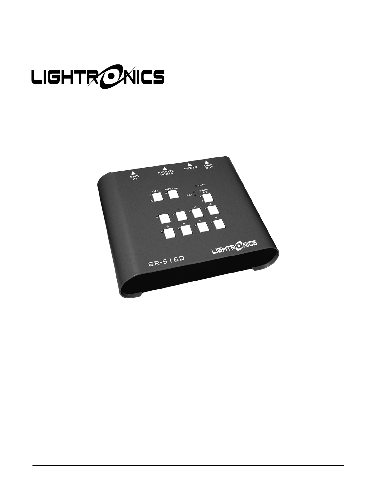
SR - 516D
DESK TOP
DMX REMOTE STATION
Version: 1.10
Date: 05/16/2013
www.lightronics.com
Lightronics Inc. 509 Central Drive Virginia Beach, Va 234354 757 486 3588
Page 2
Page 2 of 10
SR - 516D DMX REMOTE STATION
Version 1.10 OWNERS MANUAL 05/16/2013
TABLE OF CONTENTS
__________________________________________________________________
DESCRIPTION 3
__________________________________________________________________
POWER REQUIREMENTS 3
__________________________________________________________________
INSTALLATION 3
CONNECTIONS 3
POWER CONNECTIONS 3
DMX CONNECTIONS 3
REMOTES CONNECTIONS 3
PUSHBUTTON SMART REMOTES CONNECTIONS 4
SIMPLE SWITCH REMOTE STATIONS 4
__________________________________________________________________
SR-516 CONFIGURATION SETUP 4
RECORD BUTTON 5
ACCESSING AND SETTING FUNCTIONS 5
SETTING FADE TIMES 5
SIMPLE REMOTE SWITCH BEHAVIOR 5
SETTING SIMPLE SWITCH INPUT OPTIONS 5
SETTING SYSTEM CONFIGURATION OPTIONS 1 6
SETTING SYSTEM CONFIGURATION OPTIONS 2 6
CONTROLLING EXCLUSIVE SCENE ACTIVATION 6
SETTING SCENES TO BE PART OF A MUTUALLY EXCLUSIVE GROUP 6
FACTORY RESET 7
TO PERFORM A FACTORY RESET 7
__________________________________________________________________
OPERATION 7
DMX LIGHT 7
SCENE BANKS 7
TO RECORD A SCENE 7
SCENE ACTIVATION 7
TO ACTIVATE A SCENE 7
THE OFF BUTTON 8
__________________________________________________________________
MAINTENANCE AND REPAIR 8
TROUBLESHOOTING 8
OWNER MAINTENANCE 8
CLEANING8
REPAIR 8
OPERATING AND MAINTENANCE ASSISTANCE 8
__________________________________________________________________
SR-516 PROGRAMMING DIAGRAM 9
__________________________________________________________________
WARRANTY 10
www.lightronics.com
Lightronics Inc. 509 Central Drive Virginia Beach, Va 234354 757 486 3588
Page 3
Page 3 of 10
SR - 516D DMX REMOTE STATION
Version 1.10 OWNERS MANUAL 05/16/2013
DESCRIPTION
The SR-516D provides simplified remote control for
DMX-512 lighting systems. The unit can store up to
16 complete lighting scenes and activate them with
the push of a button. Scenes are organized in two
banks of eight scenes each. Scenes in the SR-516D
can operate in either an “exclusive” mode (one scene
active at a time) or in a “pile-on” mode which enables
multiple scenes to be added together.
The unit can operate with other types of Lightronics
smart remotes and simple remote switches for control
at multiple locations. These remotes are wall mount
units and connect to the SR-516D via low voltage
wiring and can turn SR-516D scenes on and off.
This unit can also be used for lighting system
operation without the use of a trained operator at the
main lighting console. The SR-516D retains stored
scenes when powered off. It can be used continuously
without a control console. The console is needed only
to create and record scenes.
POWER REQUIREMENTS
The SR-516D is powered from an external low
voltage power supply which provides +12 Volts DC at
800 mA. A UL Listed power supply is provided.
INSTALLATION
The
SR-516D
is portable and is intended to be used
on a desktop or other suitable horizontal surface. A
120 Volt AC power outlet is needed for the power
supply.
CONNECTIONS
TURN OFF ALL CONSOLES, DIMMER PACKS,
AND POWER SOURCES BEFORE MAKING
EXTERNAL CONNECTIONS TO THE SR-516D
The SR-516D is provided with connectors on the rear
edge of the unit for connection to a DMX console,
dimmer units, remote stations, and power. Tables and
diagrams for connections are included in this manual.
POWER CONNECTION
The external power connector on the rear of the unit is
a 2.1mm plug. The center pin is the positive (+) side
of the connector.
DMX CONNECTIONS
A five pin MALE XLR connector is used to connect a
DMX lighting console (needed to create scenes).
A five pin FEMALE XLR connector is used to
connect to a DMX dimmer or chain of dimmers.
DMX signals should be carried by a twisted pair,
shielded, low capacitance (25pF/ft or less) cable
DMX signal identification is shown in the table
below. It applies to both the MALE and FEMALE
connectors. Pin numbers are visible on the connector.
Connector Pin # Signal Name
1 DMX Common
2 DMX DATA 3 DMX DATA +
4 Not Used
5 Not Used
WALL REMOTES CONNECTIONS
The SR-516D can operate with two types of remote
wall stations. The first type is Lightronics pushbutton
smart remote stations. These remotes include the
Lightronics AC-1109, the AC-2116, and the AI-1001
IR remote. The other type is simple momentary
switch closures. Both remote types connect to the SR516D via a 9 pin (DB9) connector on the rear edge of
the unit. The DB9 connector pin assignments are
shown in the table below. Pin numbers are visible on
the connector face.
Connector Pin # Signal Name
1 Simple Switch Common
2 Simple Switch #1
3 Simple Switch #2
4 Simple Switch #3
5 Simple Switch Common
6 Smart Remote Common
7 Smart Remote DATA 8 Smart Remote DATA +
9 Smart Remote Voltage +
CONNECTIONS AT REMOTE UNITS
Refer to the wall remote owners manual for specific
wiring instructions for connections at the remote.
www.lightronics.com
Lightronics Inc. 509 Central Drive Virginia Beach, Va 234354 757 486 3588
Page 4

Page 4 of 10
SR - 516D DMX REMOTE STATION
Version 1.10 OWNERS MANUAL 05/16/2013
PUSHBUTTON SMART REMOTES CONNECTIONS
Communication with these stations is over a 4 wire
daisy chain bus which consists of a dual twisted pair
data cable(s). One pair carries the data (Smart
Remote DATA - and Smart Remote DATA +). The
other pair supplies power to the stations (Smart
Remote Common and Smart Remote Voltage +).
Multiple pushbutton smart remotes of mixed type can
be connected on this bus.
An example using two Lightronics AC-1109 smart
remote wall stations is shown below.
SMART REMOTE CONNECTIONS
SIMPLE SWITCH REMOTE STATIONS
The first five pins of the SR-516D DB9 connector are
used to connect simple switch remote signals. They
are COM, SWITCH 1, SWITCH 2, SWITCH 3,
COM. The two COM terminals are connected to each
other internally.
The following diagram shows an example using two
switch remotes. Several other user designed schemes
could be used to wire these remotes.
The example uses a Lightronics APP01 switch station
and a typical momentary pushbutton switch.
SIMPLE SWITCH REMOTE EXAMPLE
If a SR-516s simple switch functions are set to factory
default operation then the switches will operate as
follows for the connection example shown above.
1. Scene #1 will be turned ON when the toggle
switch is pushed up.
2. Scene #1 will be turned OFF when the toggle
switch is pushed down.
3. Scene #2 will be turned ON or OFF each time the
momentary pushbutton switch is pushed.
SR-516 CONFIGURATION SETUP
The behavior of the SR-516 is controlled by a set of
function codes and their associated values. A full list
of these codes and a brief description is shown below.
Specific instructions for each function are provided in
this manual.
11 Bank 1 Scene 1 Fade Time
12 Bank 1 Scene 2 Fade Time
13 Bank 1 Scene 3 Fade Time
14 Bank 1 Scene 4 Fade Time
15 Bank 1 Scene 5 Fade Time
16 Bank 1 Scene 6 Fade Time
17 Bank 1 Scene 7 Fade Time
18 Bank 1 Scene 8 Fade Time
21 Bank 2 Scene 1 Fade Time
22 Bank 2 Scene 2 Fade Time
23 Bank 2 Scene 3 Fade Time
24 Bank 2 Scene 4 Fade Time
25 Bank 2 Scene 5 Fade Time
26 Bank 2 Scene 6 Fade Time
27 Bank 2 Scene 7 Fade Time
28 Bank 2 Scene 8 Fade Time
31 Blackout (OFF) Fade Time)
32 ALL Scenes and Blackout Fade Time
www.lightronics.com
Lightronics Inc. 509 Central Drive Virginia Beach, Va 234354 757 486 3588
Page 5

Page 5 of 10
SR - 516D DMX REMOTE STATION
Version 1.10 OWNERS MANUAL 05/16/2013
33 Simple Switch Input #1 Options
34 Simple Switch Input #2 Options
35 Simple Switch Input #3 Options
36 Not Used
37 System Configuration Options 1
38 System Configuration Options 2
41 Mutually Exclusive group 1 scene selection
42 Mutually Exclusive group 2 scene selection
43 Mutually Exclusive group 3 scene selection
44 Mutually Exclusive group 4 scene selection
88 Factory Reset - Invokes a default configuration
A diagram at the back of this manual gives a quick
guide to programming the unit.
RECORD BUTTON
This is a very small recessed pushbutton in a small
hole in the faceplate. It is just below the RECORD
LED (labeled
REC
). You will need a small rod (such
as a ball point pen) to push it.
ACCESSING AND SETTING FUNCTIONS
1. Hold down
REC
2.
light will begin blinking.
Push
REC
RECALL.
for more than 2 seconds. The
The
RECALL
and
REC
lights
will blink alternately.
3.
Enter a 2 digit function code using the scene
buttons (1 - 8). The scene lights will flash a
repeating pattern of the code entered. The unit
will return to its normal operating mode after
about 60 seconds if no code is entered.
4. Push
RECALL
. The
RECALL
and
REC
lights
will be ON. The scene lights (in some cases
including the
OFF(0)
and
BANK(9)
lights) will
show the current function setting or value.
Your action now depends on which function was
entered. Refer to the instructions for that function.
You can enter new values and push
or push
SETTING FADE TIMES (Function Codes 11 - 32)
RECALL
to exit without changing the values.
REC
to save them
The fade time is the minutes or seconds to move
between scenes or for scenes to go ON or OFF. The
fade time for each scene can be individually set. The
allowable range is from 0 seconds to 99 minutes.
Fade time is entered as 4 digits and can be either
minutes or seconds.
Numbers entered from 0000 - 0099 will be recorded
as seconds.
Numbers 0100 and larger will be recorded as even
minutes and the last two digits will not be used. In
other words seconds will be ignored.
After accessing a function (11 - 32) as described in
ACCESSING AND SETTING FUNCTIONS:
1. The scene lights +
OFF
(0) and
BANK
(9) lights will
be flashing a repeating pattern of the current fade
time setting.
2. Use the scene buttons to enter a new fade time (4
digits). Use
3. Push
OFF
for 0 and
REC
to save the new function setting.
BANK
for 9 if needed.
Function Code 32 is a master fade time function
which will set ALL fade times to the value entered.
You can use this for a base setting for fade times and
then set individual scenes to other times as needed.
SIMPLE REMOTE SWITCH BEHAVIOR
The SR-516 is very versatile in how it can respond to
the simple remote switch inputs. Each switch input
can be set to operate according its own settings.
Most settings pertain to momentary switch closures.
The MAINTAIN setting allows the use of a regular
ON/OFF switch. When used this way, the applicable
scene(s) will be ON while the switch is closed and
OFF when the switch is open.
Other scenes can still be activated and the OFF button
will turn off the MAINTAIN scene OFF.
SETTING SIMPLE SWITCH INPUT OPTIONS
(Function Codes 33 - 35)
After accessing a function (33 - 35) as described in
ACCESSING AND SETTING FUNCTIONS:
1. The scene lights including
OFF
(0) and
BANK
(9)
will flash a repeating pattern of the current
setting.
2. Use the scene buttons to enter a value (4 digits).
Use
3. Push
OFF
for 0 and
REC
to save the new function value.
BANK A/B
for 9 if needed.
www.lightronics.com
Lightronics Inc. 509 Central Drive Virginia Beach, Va 234354 757 486 3588
Page 6

Page 6 of 10
SR - 516D DMX REMOTE STATION
Version 1.10 OWNERS MANUAL 05/16/2013
The function values and description are as follows:
SCENE ON/OFF CONTROL
0101 - 0116 Turn ON Scene (01-16)
0201 - 0216 Turn OFF Scene (1-16)
0301 - 0316 Toggle ON/OFF Scene (1-16)
0401 - 0416 MAINTAIN Scene (1-16)
OTHER SCENE CONTROLS
0001 Ignore this switch input
0002 Blackout - turn off all scenes
0003 Recall last scene(s)
SETTING SYSTEM CONFIGURATION OPTIONS 1
(Function Code 37)
The system configuration options are specific
behaviors which can be turned ON or OFF.
After accessing function code (37) as described in
ACCESSING AND SETTING FUNCTIONS:
1. The scene lights (1 - 8) will show which options
are on. An ON light means the option is active.
2. Use the scene buttons to toggle the associated
option ON and OFF.
3. Push
REC
to save the new function setting.
The configuration options are as follows:
SCENE 1 SCENE RECORD LOCKOUT
Disables scene recording. Applies to ALL scenes.
SCENE 2 DISABLE BANK BUTTON
Disables the Bank button. All scene are still available
from smart remotes if they are set to use them.
SCENE 3 SMART REMOTE LOCKOUT VIA DMX
Disables the Smart Remotes if a DMX input a from a
console is present.
SCENE 4 LOCAL BUTTON LOCKOUT VIA DMX
Disables the SR-516 scene buttons if a DMX input
from a console is present.
SCENE 5 SIMPLE REMOTE LOCKOUT VIA DMX
Disables the simple remote switches if a DMX input
from a console is present.
SCENE 6 TURN ON LAST SCENE AT POWERUP
If a scene was active when the SR-516 was powered
off then it will turn on that scene when power is
restored.
SCENE 7 EXCLUSIVE GROUP TOGGLE DISABLE
Disables the ability to turn off all the scenes in an
exclusive group. It forces the last live scene in the
group to stay on unless you push
SCENE 8 DISABLE FADE INDICATION
OFF
.
Prevents the scene lights from blinking during scene
fade time.
SETTING SYSTEM CONFIGURATION OPTIONS 2
(Function Code 38)
These options are not used during normal operation
and should always be
SYSTEM CONFIGURATION OPTIONS 1.
CONTROLLING EXCLUSIVE SCENE ACTIVATION
OFF
. They are controlled like
During normal operation multiple scenes can be active
at the same time. Channel intensities for multiple
scenes will combine in a "greatest of " manner.
You can cause a scene or multiple scenes to operate in
a exclusive manner by making them part of a mutually
exclusive group.
There are four groups which can be set. If scenes are
part of a group then only one scene in the group can
be active at any given time.
Other scenes (not part of that group) can be on at the
same time as scenes in a group.
Unless you are going to set one or two simple groups
of non overlapping scenes you may want to
experiment with the settings to get different effects.
SETTING SCENES TO BE PART OF A MUTUALLY
EXCLUSIVE GROUP (Function Codes 41 - 44)
After accessing a function (41 - 44) as described in
ACCESSING AND SETTING FUNCTIONS:
1. The scene lights will show which scenes are part of
the group. Use the
BANK A/B
button as needed to
check both banks.
2. Use the scene buttons to toggle scenes on/off for
the group.
3. Push REC to save the new group set.
www.lightronics.com
Lightronics Inc. 509 Central Drive Virginia Beach, Va 234354 757 486 3588
Page 7

Page 7 of 10
SR - 516D DMX REMOTE STATION
Version 1.10 OWNERS MANUAL 05/16/2013
FACTORY RESET (Function Code 88)
A Factory Reset will invoke the following conditions:
1. All scenes will be erased.
2. All fade times will be set to two seconds.
3. Simple switch functions will be set as follows:
Input #1 Turn ON Scene 1
Input #2 Turn OFF Scene 1
Input #3 Toggle Scene 2 ON and OFF
4. All System Configuration Options (Function
Codes 37 and 38) will be turned OFF.
5. Mutually Exclusive groups will be cleared (no
scenes in the groups).
TO PERFORM A FACTORY RESET:
After accessing the function (88) as described in
ACCESSING AND SETTING FUNCTIONS:
1. The
OFF(0)
light will repeat a pattern of 4
flashes.
2. Enter
3. Push
0516
(the model number of the product).
REC
. The scene lights will flash briefly
and the unit will return to its operating mode.
OPERATION
The SR-516 turns on automatically when power is
applied from the external power supply. There is no
ON/OFF switch or button.
When an SR-516 is not powered, a DMX signal from
a control console (if connected) is directly routed to
the dimmers via the DMX OUT connector. In other
words the console will be directly connected to the
dimmers.
DMX INDICATOR LIGHT
This indicator conveys the following information
about the DMX input and DMX output signals.
1. OFF DMX is NOT being received.
DMX is NOT being transmitted to dimmers
(No scenes are active).
2. BLINKING DMX is NOT being received.
DMX IS being transmitted
(one or more scenes are active).
3. ON DMX is being received.
DMX is being transmitted to the dimmers.
SCENE BANKS
The SR-516 can store 16 operator created scenes and
activate them with the push of a button. Scenes are
organized in two banks (A and B). A bank switch
button and indicator are provided for switching
between banks. Bank "B" is active when the
light is on.
A/B
TO RECORD A SCENE
BANK
A DMX console or controller must be connected and
used to create the scene to be stored in the SR-516.
Check that Scene Record Lockout is OFF.
1. Create a scene using the control console faders to
set dimmer channels to the desired levels.
2. Select the bank where you want to store the scene.
3. Hold down
REC
on the SR-516 until its LED
and the scene lights begin to flash (about 2 sec.).
4. Push the button for the scene you want recorded.
The
REC
and scene lights will go
OFF
which
shows that recording was completed.
The
REC
and scene lights will stop flashing after
about 20 seconds if you do not select a scene.
5. Repeat steps 1 through 4 to record other scenes.
SCENE ACTIVATION
Playback of scenes stored in the SR-516 will occur
regardless of control console operation or status. This
means that scenes activated from the unit will add to
or “pile on” to the channel data from a DMX console.
TO ACTIVATE A SCENE
1. Set the SR-516 to the desired scene bank.
2. Push the button associated with the desired scene.
The scene will fade in according to the fade time
function settings.
The scene light will blink until the scene reaches
its full level. It will then be ON. The blink
action can be disabled by a configuration option.
The scene activation buttons are toggles. To turn off
an active scene – push its associated button.
www.lightronics.com
Lightronics Inc. 509 Central Drive Virginia Beach, Va 234354 757 486 3588
Page 8

Page 8 of 10
SR - 516D DMX REMOTE STATION
Version 1.10 OWNERS MANUAL 05/16/2013
Scene activation can be either "exclusive" (only one
scene may be active at a time) or "pile on" (multiple
scenes on at the same time) depending on setup
function selections. During "pile on" operation multiple active scenes will combine in a "greatest of "
fashion with respect to channel intensity.
THE OFF BUTTON
The
OFF
button blacks out or turns off all active
scenes. Its indicator is on when active.
RECALL LAST SCENE
The
RECALL
button can be used to reactivate the
scene or scenes which were on prior to an OFF
condition. The
RECALL
indicator will light when a
recall is in effect. It will not step back through a
series of previous scenes.
MAINTENANCE AND REPAIR
TROUBLESHOOTING
1. A valid DMX console signal must be present to
record a scene.
2. If a scene does not activate correctly – it may have
been overwritten without your knowledge.
3. If you cannot record scenes – check that the
record lockout option is not on.
4. Check that the DMX cables and/or remote wiring
are not defective. A MOST COMMON
PROBLEM SOURCE.
5. To simplify troubleshooting - set the unit to known
set of conditions. A factory reset can be
performed
6. Make sure that the dimmer addresses are set to the
desired channels.
7. Check that the console softpatch (if applicable) is
set correctly.
OWNER MAINTENANCE
CLEANING
The best way to prolong the life of your SR-516 is to
keep it dry, cool, and clean.
COMPLETELY DISCONNECT THE UNIT BEFORE
CLEANING AND MAKE SURE IT IS COMPLETELY
DRY BEFORE RECONNECTING
The unit exterior may be cleaned using a soft cloth
dampened with a mild detergent/water mixture or a
mild spray-on type cleaner. DO NOT SPRAY ANY
LIQUID directly on the unit. DO NOT IMMERSE
the unit in any liquid or allow liquid to get into the
controls. DO NOT USE any solvent based or abrasive
cleaners on the unit.
REPAIRS
There are no user serviceable parts in the unit.
Service by other than Lightronics authorized agents
will void your warranty.
OPERATING AND MAINTENANCE ASSISTANCE
Dealer and Lightronics factory personnel can help you
with operation or maintenance problems. Please read
the applicable parts of this manual before calling for
assistance.
If service is required - contact the dealer from whom
you purchased the unit or contact Lightronics, Service
Dept., 509 Central Drive, Virginia Beach, VA
23454 TEL: (757) 486-3588.
www.lightronics.com
Lightronics Inc. 509 Central Drive Virginia Beach, Va 234354 757 486 3588
Page 9

Page 9 of 10
R
SR - 516D DMX REMOTE STATION
Version 1.10 OWNERS MANUAL 05/16/2013
-516 PROGRAMMING DIAGRAM
S
www.lightronics.com
Lightronics Inc. 509 Central Drive Virginia Beach, Va 234354 757 486 3588
Page 10
Y
All Lightronics products are warranted for a period of TWO/FIVE YEARS from the date of
purchase against defects in materials and workmanship.
WARRANT
This warranty is subject to the following restrictions and conditions:
A) If service is required, you may be asked to provide proof of purchase from an authorized
Lightronics dealer.
B) The FIVE YEAR WARRANTY is only valid if the warranty card is returned to Lightronics
accompanied with a copy of the original receipt of purchase within 30 DAYS of the purchase
date, if not then the TWO YEAR WARRANTY applies. Warranty is valid only for the original
purchaser of the unit.
C) This warranty does not apply to damage resulting from abuse, misuse, accidents, shipping,
and repairs or modifications by anyone other than an authorized Lightronics service
representative.
D) This warranty is void if the serial number is removed, altered or defaced.
E) This warranty does not cover loss or damage, direct or indirect arising from the use or
inability to use this product.
F) Lightronics reserves the right to make any changes, modifications, or updates as deemed
appropriate by Lightronics to products returned for service. Such changes may be made
without prior notification to the user and without incurring any responsibility or liability for
modifications or changes to equipment previously supplied. Lightronics is not responsible
for supplying new equipment in accordance with any earlier specifications.
G) This warranty is the only warranty either expressed, implied, or statutory, upon which the
equipment is purchased. No representatives, dealers or any of their agents are authorized
to make any warranties, guarantees, or representations other than expressly stated herein.
H) This warranty does not cover the cost of shipping products to or from Lightronics for
service.
I) Lightronics Inc. reserves the right to make changes as deemed necessary to this warranty
without prior notification.
Lightronics Inc. 509 Central Drive Virginia Beach, VA 23454 20050125
 Loading...