

Page 1

SM - 192
DMX LIGHTING CONTROLLER
OWNERS MANUAL
May 19, 2009
www.lightronics.com
Lightronics Inc. 509 Central Drive Virginia Beach, VA 23454 757 486 3588
Page 2
INSTRUCTION MANUAL Page 2 of 8
SM - 192 DMX LIGHTING CONTROLLER
Version 20090519
MAIN FEATURES
192 DMX Channels
30 Scene Banks of 8 programmable scenes each
6 Programmable chases with up to 240 steps each
8 Faders for output level adjustment
Built-in microphone for Music Auto-Run
AUTO mode controlled by TAP SYNC and SPEED
MIDI control through MIDI interface
4 digit LED display
Blackout Function
Fade Time control
Power Input: +9 - +12VDC, 300mA minimum
Power Connector: 2.1mm, Center Pin Positive
Dimensions: 482 x 132 x 73 mm
Weight: 2.5Kg
GENERAL DESCRIPTION
The SM-192 is a fixture (or scanner) oriented DMX
controller. It can control up to 12 fixtures of 16 DMX
channels each. The unit can also be used to control
conventional dimmer packs. The SM-192 includes 30
banks of user programmable scenes. Each bank can
contain up to 8 scenes. There are also 6 programmable
chases. Each chase may contain up to 240 steps.
Scene banks can be automatically run like chases.
FIXTURE CHANNEL ASSIGNMENTS
Each fixture is permanently assigned a 16 channel
block of DMX addresses. The table below shows the
assignments.
Fixture # Channel
1 1-16
2 17-32
3 33-48
4 49-64
5 65-80
6 81-96
7 97-112
8 113-128
9 129-144
10 145-160
11 161-176
12 177-192
The fixtures must be set to accommodate these DMX
assignments. This is usually done using DIP switches
on the fixture. Refer to the fixture manual for exact
instructions for this procedure. This information is
sometimes shown on a tag or chart on the fixture.
If you set multiple fixtures to the same addresses then
they will respond to the SM-192 as one fixture.
www.lightronics.com
Lightronics Inc. 509 Central Drive Virginia Beach, VA 23454 757 486 3588
FIXTURE FUNCTIONS
You will need to know which channel within a fixture
is assigned to each fixture function (Pan, Tilt, Color,
Dimming, etc.). This information is normally given in
the fixture manual.
DMX CONNECTIONS
Any system using DMX control should be connected
together as a chain of devices. In other words the
control cable should proceed from the controller to the
first fixture and then to other fixtures in a continuous
"daisy chain" fashion. Most fixtures have a DMX IN
and a DMX OUT connector to be used to connect the
chain. The control cable should NOT be split into a
multiple run star arrangement with a cable running
from the controller directly to each fixture.
DMX CONNECTOR PIN ASSIGNMENTS
There are two different connectors which can be used
for DMX control. They are both XLR type connectors.
Some units use 3 pin connectors. Others use 5 pin
connectors. The SM-192 transmits from a 3 pin female
connector on the back edge of the unit. If your fixtures
use 5 pin connectors then you can make up an adapter
cable to accommodate this.
There are some fixtures using a reversed signal
scheme. In this case the DATA - and DATA + pins are
reversed. The SM-192 has a reversing switch on the
back edge to handle this situation. The table below
shows the pin assignments for both normal and
reversed operation.
PIN # NORMAL REVERSED
1 DMX COMMON DMX COMMON
2 DMX DATA - DMX DATA+3 DMX DATA + DMX DATA 4 NOT USED NOT USED
5 NOT USED NOT USED
DMX TERMINATION
A DMX chain should be terminated at the last fixture
(and ONLY the last fixture) on the chain. This is done
by installing a commonly available 1/4 Watt, 120 Ohm
resistor across the DATA - and DATA + wires at the
last fixture. If you have only a few fixtures very close
together and a very short run to the controller then you
may be able to operate without the terminator.
Page 3
INSTRUCTION MANUAL Page 3 of 8
SM - 192 DMX LIGHTING CONTROLLER
Version 20090519
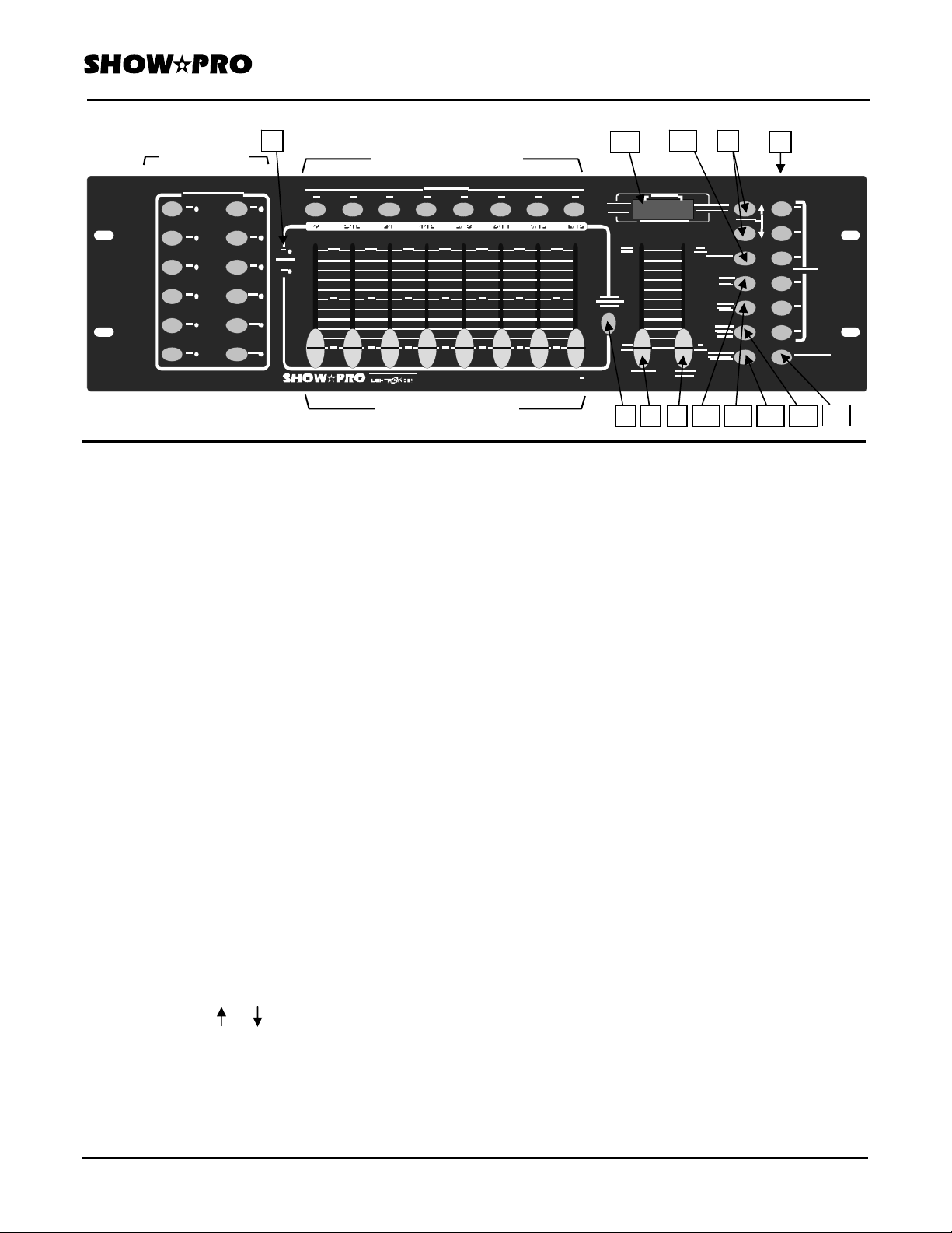
(1) FIXTURE
SELECTORS
(2) SCENE SELECTORS
(3) CHANNEL FADERS
CONTROLS & FUNCTIONS
1 Fixture (Scanners) Selectors: Used to select one
or more of the 12 fixtures which can be controlled by
the SM-192. Each fixture is a block of 16 DMX
channels. The selectors are used in both programming
and manual modes
2 Scene Selectors: Selects a scene in the current
scene bank for programming or playback. The scene
currently selected is shown on the DISPLAY.
3 Channel Faders: Adjusts output level of a DMX
channel.
4 PAGE SELECT A/B: Selects fader page A or page
B. Page A is channels 1-8 of the selected fixture. Page
B is channels 9 - 18.
5 Active Page Indicator: Shows which page has been
selected by the
6 Speed Fader: Adjusts the speed of auto triggered
Page Select A/B button.
scenes and chases. The display shows the setting (in
seconds) when this fader is used.
7 Fade Time Fader: Adjusts the fade time for scenes
and chases. The display shows the setting (in seconds)
when this fader is used
8 Bank Buttons ( or ): Selects a scene bank. The
third and fourth display digits show the currently active
bank number (01-30). Also used for during some
chase programming operations
10 5 8
9 16
1 0 1
SM 192
4
9 Chase Selectors:
6 7 11
Selects a chase for programming
14
12 13
or playback.
10 PROGRAM: Switches unit into programming mode
to create and record scenes and chases. Hold for 3
seconds to toggle program mode ON and OFF. The
display has a flashing indicator mark which shows
when the program mode is active. A BLACKOUT
condition is invoked when exiting the program mode.
Push BLACKOUT to turn blackout off.
11 MIDI/ADD:
MIDI: Toggles MIDI mode ON and OFF and selects
MIDI address.
ADD: Records a chase step or a scene setting in
program mode.
12 AUTO/DEL:
AUTO: Toggles Activation of Auto-Run triggering for
chases or scenes. The display has an indicator
mark showing when the auto mode is active.
DEL: Deletes scenes, complete banks of scenes,
chase steps or complete chases in program
mode.
13 MUSIC/BANK COPY:
MUSIC: Toggles activation of Music Auto-Run. It
uses an internal microphone to synchronize
chases or scenes to music. The display has
an indicator showing when the music trigger
mode is active.
15
www.lightronics.com
Lightronics Inc. 509 Central Drive Virginia Beach, VA 23454 757 486 3588
Page 4

INSTRUCTION MANUAL Page 4 of 9
SM - 192 DMX LIGHTING CONTROLLER
Version 20090519
BANK COPY: Copies the contents of a scene bank to
another bank in program mode.
14 TAPSYNC/DISPLAY:
TAPSYNC: Controls speed of scenes or chases. Tap
it several times at the rate you want the
chase or scenes to run at. This as an
alternative to using the SPEED Fader.
The display shows the results (in seconds)
when this button is used.
DISPLAY: Switches the display between STEP and
BANK. In other modes it switches the
DMX output level display between 00-
225 and 0%-100%.
15 BLACKOUT: Disables all DMX channel output.
Blackout toggles On/Off.
16 LED Display: Shows the active scene and bank
number, current chase and step number, fader level
settings, and contains other indicators for various
functions. When adjusting faders the display shows
the current level setting. This can be switched between
showing the level as 0 - 255 or showing it as 0% 100% by pushing TAPSYNC/DISPLAY.
REAR PANEL CONTROLS
12 3 4 5
1 Power Switch: Turns controller ON/OFF. Can be
used with other buttons to erase scenes and chases.
2 MIDI IN Connector: Used to receive MIDI data..
3 DMX Polarity Switch: Selects the polarity of DMX
output. Shown above in NORMAL position. See
DMX CONNECTOR PIN ASSIGNMENTS.
4 DMX OUT Connector: Main control signal output
to fixtures and other DMX receiving devices.
5 DC Input Connector: Provides connection for the
external power supply. DC 9V-12V, 300mA Min..
OPERATION
When the SM-192 is powered on it is in its MANUAL
mode. No fixtures are selected. All chases are OFF.
Auto scene triggering is OFF.
www.lightronics.com
Lightronics Inc. 509 Central Drive Virginia Beach, VA 23454 757 486 3588
MANUAL FIXTURE OPERATION
To control a fixture manually - Push the desired fixture
(SCANNERS) button. The fixture indicator will light,
and the channel faders are enabled. If the fixture has
more than 8 channels you must use PAGE SELECT
A/B to access channels 9 - 16. You can select more
than one fixture and control them together if
applicable. To deselect a fixture - push its selector
button again.
PROGRAMMING SCENES
There are a total of 30 scene banks. Only one can be
selected at a time. Each bank contains 8 scenes which
are user programmable.
ALL SCENE RECORD, EDIT, DELETE, AND COPY
FUNCTIONS ARE DONE IN THE PROGRAM MODE.
Hold down PROGRAM for about 3 second to activate
program mode. The display PROGRAM indicator will
flash continuously when program mode is active.
RECORD A SCENE
1. Push a SCANNERS button to select a fixture. You
can select more than one to control several at once.
2. Adjust the appropriate faders to set the desired
output level for each channel.
3. Deselect the fixture and select another one. Your
settings for the first fixture will remain in active.
You can now adjust output levels again but for a
different fixture.
4. Repeat steps 2 and 3 until all settings for all desired
fixtures have been made.
5. Push MIDI/ADD.
6. Select desired bank to store the scene using BANK
UP or BANK DOWN.
7. Push a SCENES button (1 - 8) to complete the
recording. The display will flash briefly indicating
that recording is complete.
8. Deselect the fixtures by pushing the appropriate
SCANNERS buttons.
9. Exit from the program mode by holding down
PROGRAM for about 3 seconds.
Page 5

INSTRUCTION MANUAL Page 5 of 9
SM - 192 DMX LIGHTING CONTROLLER
Version 20090519
EDIT A SCENE
1. Select desired bank to store the scene in using
BANK UP or BANK DOWN.
2 Select desired scene within the bank by pushing its
SCENES button (1 - 8).
3. Select the fixture(s) to be affected by pushing the
associated SCANNERS buttons.
4. Adjust the appropriate faders to set the desired
output level for each channel.
5. Push MIDI/ADD.
6. Push the SCENES button used in step 2 to store the
edited scene. The display will flash briefly to
indicate that recording is complete.
7. Deselect any fixtures you have used during editing
and exit from PROGRAM mode.
COPY FIXTURE SETTINGS
You can copy the settings of a fixture to another while
programming a scene.
1. While a fixture is selected, hold its SCANNERS
button down.
2. Push the SCANNERS button of the fixture to copy
the fixture settings to.
COPY A SCENE
You can copy the contents of a scene to another scene
in the same or different bank.
1. Select the bank holding the scene you want to
copy from using BANK UP or BANK DOWN.
2 Select desired scene within the bank by pushing it's
SCENES button (1 - 8).
3. Push MIDI/ADD.
4. Select the bank which you want to copy to using
BANK UP or BANK DOWN.
5. Push the SCENES button for the scene to copy to.
The display will flash briefly indicating that the
copy has been completed.
COPY A BANK OF SCENES
This will copy the entire contents of a scene bank to
another bank.
1. Select the bank you want to copy FROM using
BANK UP or BANK DOWN.
2. Push MIDI/ADD.
3. Select the bank you want to copy TO using
BANK UP or BANK DOWN.
4. Push MUSIC/BANK COPY. The display will
flash briefly indicating that the copy has been
completed.
DELETE A SCENE
This will set all channels of all fixtures associated with
the scene to zero output level.
1. Select the bank which contains the scene you want
to delete using BANK UP or BANK DOWN.
3. Hold down AUTO/DEL and push the SCENES
button (1 - 8) for the scene to be deleted. The
display will flash briefly indicating that the
deletion is complete.
DELETE ALL SCENES IN A BANK
1. Select the bank to be deleted using BANK UP or
BANK DOWN.
2. Hold down AUTO/DEL and push MUSIC/BANK
COPY. The display will flash briefly indicating the
deletion is complete.
CLEAR ALL SCENES
This will delete ALL scenes in ALL banks.
1. Turn OFF the SM-192.
2. Hold down PROGRAM and BANK DOWN while
turning the power back on.
3. Keep the buttons held down for a few seconds
until the display flashes briefly.
www.lightronics.com
Lightronics Inc. 509 Central Drive Virginia Beach, VA 23454 757 486 3588
Page 6

INSTRUCTION MANUAL Page 6 of 9
SM - 192 DMX LIGHTING CONTROLLER
Version 20090519
PROGRAMMING CHASES
The SM-192 contains 6 user programmable chases.
Each chase may include up to 240 steps.
EACH CHASE STEP CONSISTS OF A SCENE
WHICH HAS ALREADY BEEN RECORDED.
A chase step can use any scene in any bank. Any scene
can be used in multiple chase steps and multiple
chases.
ALL CHASE RECORD, EDIT, DELETE, AND COPY
FUNCTIONS ARE DONE IN THE PROGRAM MODE.
Hold down PROGRAM for about 3 second to activate
program mode. The display PROGRAM indicator will
flash continuously when program mode is active.
RECORD A CHASE
1. Select any chase (1 - 6) by pushing the applicable
CHASE button.
2. Select the scene bank which contains the scene to
be used for the chase step using BANK UP or
BANK DOWN.
3. Select the scene to be used for the chase step by
pushing its SCENES button (1 - 8).
4. Push MIDI/ADD. The display will flash several
times indicating recording of the step.
5. Repeat instruction steps 2 through 4 above as many
times as needed to record additional steps in the
selected chase. You can record up to 240 steps.
6. Exit from the program mode by holding down
PROGRAM for about 3 seconds.
COPY A SCENE BANK TO A CHASE
This will copy the contents of a scene bank into a
chase.
1. Select the bank you want to copy from using
BANK UP or BANK DOWN.
2. Select the chase you want to copy it TO by pushing
its CHASE selector button.
3. Push MUSIC/BANK COPY
4. Push MIDI/ADD. The display will flash briefly
indicating that the copy is completed.
www.lightronics.com
Lightronics Inc. 509 Central Drive Virginia Beach, VA 23454 757 486 3588
INSERT A STEP INTO A CHASE
1. Select a chase (1 - 6) by pushing the applicable
CHASE button.
2. Push TAPSYNC/DISPLAY. The display will
show the current chase and step.
3. Use BANK UP or BANK DOWN to advance to the
step BEFORE the step you want to insert.
4. Push MIDI/ADD. The display shows the next step.
5. Push the SCENES button (1 - 8) for the scene you
want to insert. Use BANK UP or BANK DOWN
if the scene to be inserted is in a different bank.
6. Push MIDI/ADD. The display will flash briefly
indicating that the insertion is complete.
DELETE A STEP IN A CHASE
1. Select a chase (1 - 6) by pushing the applicable
CHASE button.
2. Push TAPSYNC/DISPLAY
3. Use BANK UP or BANK DOWN to advance to the
step you want to delete.
4. Push AUTO/DEL. The display will flash briefly
indicating that the step is deleted.
DELETE A COMPLETE CHASE
1. Hold down the CHASE button for the chase you
want to delete.
2. Push AUTO/DELETE. The display will flash
briefly indicating that the chase has been deleted.
3. Release both buttons.
CLEAR ALL CHASES
This will delete ALL steps of ALL chases. It does not
clear scenes.
1. Turn OFF the SM-192.
2. Hold down the BANK DOWN button AND the
AUTO/DEL button while turning the SM-192
power back ON. Keep the buttons held down for a
few seconds until the display flashes several times.
3. Release both buttons.
Page 7

INSTRUCTION MANUAL Page 7 of 9
SM - 192 DMX LIGHTING CONTROLLER
Version 20090519
OPERATING SCENES
When the SM-192 is turned on it is in the manual scene
mode with bank 1 scene 1 active.
ACTIVATE A SCENE MANUALLY
1. Turn off PROGRAM mode, AUTO, MUSIC, and
all chases.
2. Select the desired scene bank using BANK UP or
BANK DOWN.
3. Push the SCENES button for the scene you want to
activate.
RUN A BANK OF SCENES AUTOMATICALLY
The scene Auto-Run function will cycle through a
bank of scenes continuously. The speed and scene
fade time can be controlled by operator. The speed is
controlled by the TAPSYNC button or the SPEED
fader. The fade time is controlled by the FADE TIME
fader. Scenes can also be synchronized to music or
MIDI note triggering.
1. Select the desired scene bank using BANK UP or
BANK DOWN.
2. Push AUTO/DEL. The AUTO TRIGGER
indicator on the display will light and scene Auto Run will begin cycling.
3. You can adjust the speed and fade time as needed.
If you set a speed faster than the fade time then the
scenes will advance before the fade is complete.
4. You can switch to another bank at any time using
BANK UP and BANK DOWN.
5. Push AUTO/DEL to stop Auto-Run. The AUTO
TRIGGER indicator on the display will go OFF.
RUN SCENES AUTOMATICALLY WITH MUSIC
SYNC
The SM-192 has an internal microphone which can be
used to Auto-Run scenes with music synchronization.
SCENE MUSIC AUTO-RUN
1. Push MUSIC/BANK COPY. The MUSIC
TRIGGER indicator on the display will light.
and Music Auto-Run will begin in the currently
selected scene bank.
www.lightronics.com
Lightronics Inc. 509 Central Drive Virginia Beach, VA 23454 757 486 3588
2. You can switch to a different scene bank using
BANK UP or BANK DOWN.
3. Push MUSIC/BANK COPY to stop Music Auto Run.
OPERATING CHASES
Chases can be run in several ways including Manual,
Auto-Run, and Music Auto-Run.
MANUAL CHASE OPERATION
This is used to manually step through a chase. It is
done in program mode and is useful when creating or
editing chases.
1. Enter the program mode.
2. Select a chase (1 - 6) by pushing the applicable
CHASE button.
3. Push TAP/SYNC. The display will show the chase
and step numbers and the display STEP indicator
will light.
4. Use the BANK UP and BANK DOWN buttons to
cycle through the chase steps.
5. When finished, exit from the program mode by
holding down PROGRAM for aprox. 3 seconds.
RUN A CHASE AUTOMATICALLY
The chase Auto-Run function will continuously cycle a
chase. Multiple chases can be run together and will
run in the order selected. The speed and fade time can
be controlled by operator. Speed is controlled by the
TAP SYNC button or the SPEED fader. Fade time is
controlled by the FADE TIME fader.
1. Select a chase (1 - 6) by pushing the applicable
CHASE button. You can select more than one.
2. Push AUTO/DEL. The AUTO TRIGGER indicator
in the display will light and the chase(s) will run.
3. You can adjust the speed and fade time as needed.
4. Push AUTO/DEL to stop chase Auto-Run. The
display AUTO TRIGGER indicator will go OFF.
NOTE: If you turn off all chases before you turn off
Auto-Run then the SM-192 will revert to scene AutoRun in the last accessed scene bank.
Page 8

INSTRUCTION MANUAL Page 8 of 9
SM - 192 DMX LIGHTING CONTROLLER
Version 20090519
CHASE MUSIC AUTO-RUN
The SM-192 has an internal microphone which can be
used to Auto-Run chases with music synchronization.
1. Select a chase (1 - 6) by pushing the applicable
CHASE button. You can select more than one.
2. Push MUSIC/BANK COPY. The MUSIC
TRIGGER indicator on the display will light.
and Music Auto-Run will begin.
3. Push AUTO/DEL to stop chase music Auto-Run.
The display indicator in the display will go OFF.
MIDI OPERATIONS
MIDI CONTROL ACTIVATION
1. Hold down MIDI/ADD for about 3 seconds. The
third and fourth digits of the display will begin to
flash indicating that MIDI Control is ON and will
show the current MIDI channel.
MIDI Control is turned OFF by the same procedure.
MIDI CHANNEL SELECTION
You can change the MIDI channel (1 - 16) when MIDI
Control is ON using BANK UP and BANK DOWN.
MIDI RUN
The SM-192 uses MIDI "NOTE ON" commands to
execute scene and chase function. You might have to
transpose a MIDI keyboard to send the correct notes.
www.lightronics.com
Lightronics Inc. 509 Central Drive Virginia Beach, VA 23454 757 486 3588
The table below shows the SM-192 functions which
can be controlled by MIDI.
MIDI NOTE FUNCTION
00 - 07 Bank 1 Scenes 1 - 8 ON/OFF
08 - 15 Bank 2 Scenes 1 - 8 ON/OFF
16 - 23 Bank 3 Scenes 1 - 8 ON/OFF
24 - 31 Bank 4 Scenes 1 - 8 ON/OFF
32 - 39 Bank 5 Scenes 1 - 8 ON/OFF
40 - 47 Bank 6 Scenes 1 - 8 ON/OFF
48 - 55 Bank 7 Scenes 1 - 8 ON/OFF
56 - 63 Bank 8 Scenes 1 - 8 ON/OFF
64 - 71 Bank 9 Scenes 1 - 8 ON/OFF
72 - 79 Bank 10 Scenes 1 - 8 ON/OFF
80 - 87 Bank 11 Scenes 1 - 8 ON/OFF
88 - 95 Bank 12 Scenes 1 - 8 ON/OFF
96 - 103 Bank 13 Scenes 1 - 8 ON/OFF
104 - 111 Bank 14 Scenes 1 - 8 ON/OFF
112 - 119 Bank 15 Scenes 1 - 8 ON/OFF
120 - 125 CHASES 1 - 6 ON/OFF
126 BLACKOUT
Page 9

W
Y
All products are warranted for a period of TWO YEARS from the date of
purchase against defects in materials and workmanship.
ARRANT
This warranty is subject to the following restrictions and conditions:
A) If service is required, you may be asked to provide proof of purchase from an authorized
Lightronics dealer.
B) This warranty is valid only for the original purchaser of the unit.
C) This warranty does not apply to damage resulting from abuse, misuse, accidents, shipping,
and repairs or modifications by anyone other than an authorized Lightronics service
representative.
D) This warranty is void if the serial number is removed, altered or defaced.
E) This warranty does not cover loss or damage, direct or indirect arising from the use or
inability to use this product.
F) Lightronics reserves the right to make any changes, modifications, or updates as deemed
appropriate by Lightronics to products returned for service. Such changes may be made
without prior notification to the user and without incurring any responsibility or liability for
modifications or changes to equipment previously supplied. Lightronics is not responsible
for supplying new equipment in accordance with any earlier specifications.
G) This warranty is the only warranty either expressed, implied, or statutory, upon which the
equipment is purchased. No representatives, dealers or any of their agents are authorized
to make any warranties, guarantees, or representations other than expressly stated herein.
H) This warranty does not cover the cost of shipping products to or from Lightronics for
service.
I) Lightronics Inc. reserves the right to make changes as deemed necessary to this warranty
without prior notification.
Lightronics Inc. 509 Central Drive Virginia Beach, VA 23454 20080205
Page 10

www.lightronics.com
Lightronics Inc. 509 Central Drive Virginia Beach, VA 23454 757 486 3588
 Loading...