

Page 1
Page 1 of 6
SC-810 DMX CONTROLLER
Version 0.1 OWNERS MANUAL 11/10/2015
DESCRIPTION
The SC-810 is designed to be a compact, DMX controller
and snapshot playback station. When used as a standalone
controller, the SC-810 is capable of independently
controlling 512 channels of DMX and has the ability to
record 18 scenes. The scene control is broken down to 10
real time fader controls and 8 push buttons with user defined
fade times. This device features the ability to set a fixed
output val ue or park DMX channe ls. In addition, the SC810 is able to connect to a DMX data chain with another
controller or DMX co nsole; whe n another DMX contr oller
on the circuit is transmitting DMX, t he SC -810 will lock out
local control and enter a mode that allows it to record any of
the 18 available scenes via DMX snapshot.
Available as either a desktop or wall mounted unit , the SC810 is the ideal device for architectural control of DMX512
lighting systems, it can be used as a backup to a DMX
console, great for controlling LED lighting for special
events or anywhere that requires quick, easy control of a full
universe o f DMX.
INSTALLATION
POWER AND DATA
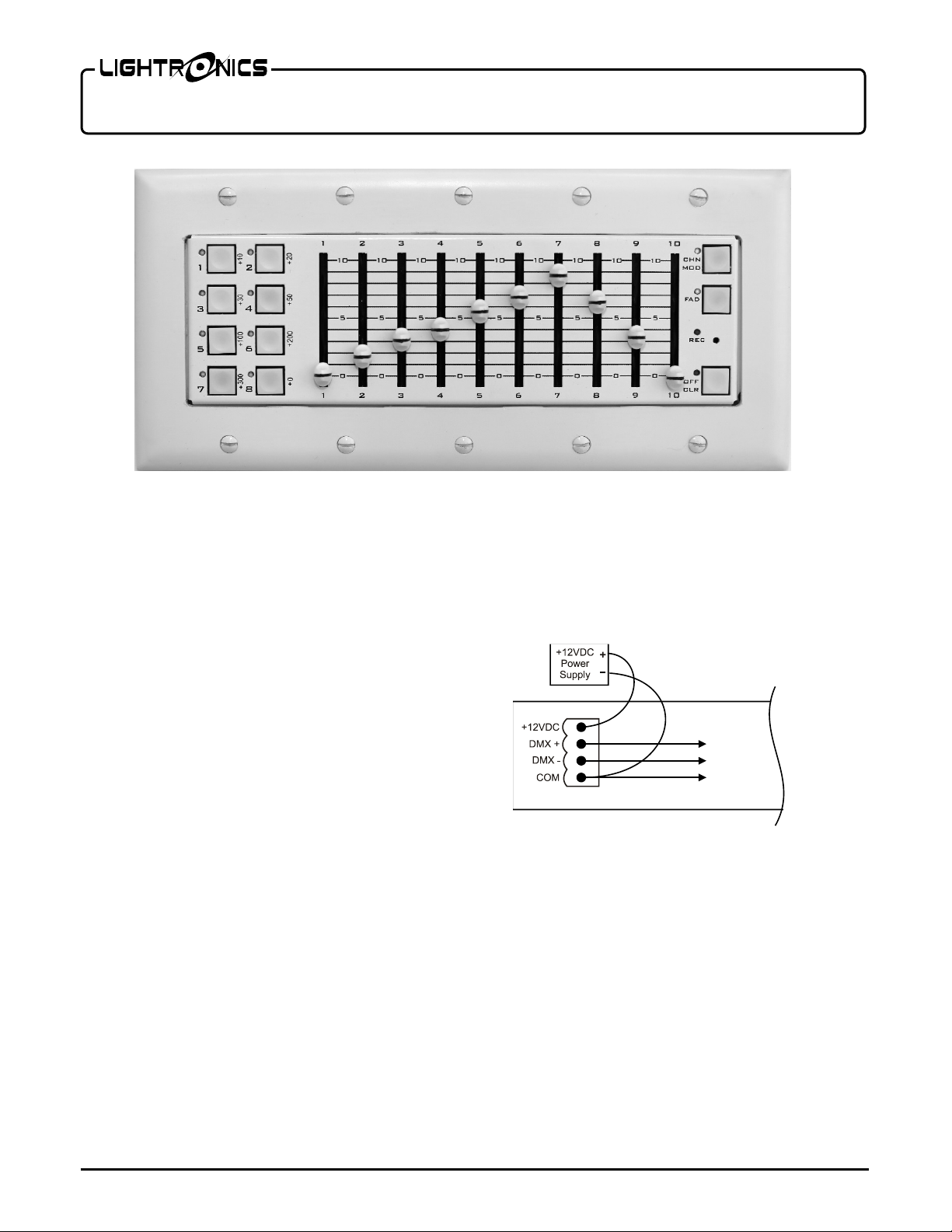
SC-810 uses an external 12 Volt/ 1 amp, DC power supply,
which is included. Installing power to a wall mount will
require landing the red wire to the +12VDC and the black
wire to the COM t erminal on the four pin p lug located on
the back of the device.
When in stalling po wer and DMX connections to the device,
make all low voltage connections and check DC output
prior to mating the connector with the male pins located on
www.lightronics.com
Lightronics Inc. 509 Central Drive V i rgi ni a Beach, VA 23454 757 486 3588
the rear of the SC-810. Do not ma ke an y of the connections
LIVE or while any devices on the DMX data chain are
transmitting.
DMX is installed in a similar way on the removable 4 pin
connector. Fig 1.1 shows the prop er wiring of the connector.
Fig. 1.1
Make all necessary voltage and DMX connections prior to
powering on the device. Connect the power supply to the
low voltage receptacle on the back of the device, then plug
the power supply into the 120v receptacle. Use only the
power supply provided with the SC-810.
On the SC-810D, a female 5 pin XLR style plug is located
beside the power on the rear face of the unit. ( Fig 1.2) T his
can be used as both a DMX input for snapshotting scenes, as
well as a DMX output.
A male-to-male 5 pin DMX adapter is required when
inputting DMX signal from a console or other output
device.
Page 2
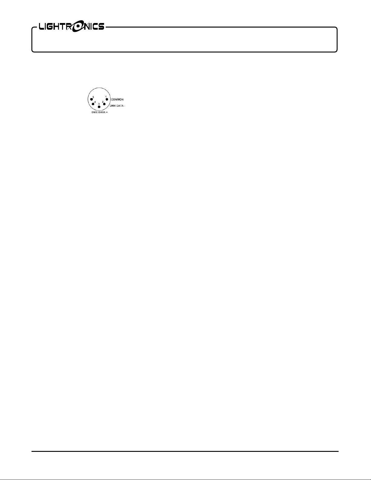
5 PIN FEMALE X L R CONNECTOR
Page 2 of 6
SC-810 DMX CONTROLLER
Version 0.1 OWNERS MANUAL 11/10/2015
Fig. 1.2
FACE VIEW
default to sce ne mod e. W he n in t his mode, the unit acts as a
replay device, each of the buttons and faders will recall any
previously recorded scenes.
When the CHN/MOD button is pressed, the amber LED
beside the button will il luminate , signifying tha t the SC -810
is now i n channel mode. In t his mode, the device can be
used like a DMX console or scene setter, allowing the use r
DESK TOP INSTALLATION
The SC-810D (or desk top model) is built into a desk to p
chassis designed to sit on a desk, podium or shelf.
Install in a dry place away from excessive dust, heat or
moisture.
DMX DATA NETWORK
For the best re sults, it is advised that - when installed on a
large DMX data network or any networ k co ntai nin g de vice s
with “Master/Slave” functions such as select Lightronics
FXLD or FXLE fixtures - an optically isolated splitter be
installed on the output side o f t he S C-810 in the DMX Data
chain.
Desk top units used with and external DMX controller
should have t he controllers output connected to the output
of the SC-810. T he DMX li ne should then be daisy chained
to a splitter or the first DMX co ntrolled device in the data
chain.
WALL INSTALLATION
The SC-810W (or wall mount) is designed to fit in a
standard 5 gang “new work” st yle junction box. Be certain
to keep line voltage and earth ground connections away
from SC-81 0W and the junction box housing the unit.
OPERATION
Upon start up, the SC-810 will flash the software version
number then go to an OFF state, illuminating the “OFF”
LED. To ve ri fy that the u nit h as contro l of the s ystem and is
operating properly, press the OFF/CLR button. Once
pressed, the SC-810’s OFF/CLR red LE D should turn off.
Press CHN/MOD and follow all steps in the next two
sections of this manual to set outputs. If the SC-810 is
actively receiving a DMX signal, the OFF/CLR LED will
blink slowly.
CHN/MOD BUTTON AND LED
The SC-810’s CHN/MOD button is used to toggle between
scene and channel mode. After startup, the device will
www.lightronics.com
Lightronics Inc. 509 Central Drive V i rgi ni a Beach, VA 23454 757 486 3588
to set, change/modify/store scenes on any combination of
levels using up to 512 DMX channels.
SETTING CHANNEL LEVELS
The ten faders on the SC-810 user interface are used to set
levels for a block of ten DMX channels at a time. Once set,
those levels remain live until they are changed, a clear
command is given, or the device senses DMX from another
DMX console in li ne. The SC-810 uses a unique addressing
system to access blocks of faders.
DMX channels 1 - 10 are the defaults for fader operation
when the uni t is po wered up and switched to channel mode.
To access a block of ten c hannels o ther than the d efault (1-
10) the S C-810 uses additive addressing. Utilizing the eight
buttons on the left side of the unit, labeled ‘+10’, ‘+20’,
‘+30’, ‘+50’ etc. Addressing is achieved by pushing a
combination adding up to the desired DMX start address.
Any block of ten channels out of the 512 available channels
are accessible using this procedure buttons.
For example, to access channel 25 6 when starting with the
default ‘+0’, press ‘+50’, ‘+200’. 256 will then be on fader
6. To access channel 250, again starting from the default,
press +200, +30, and +10. Channel 250 will now be the 10
fader (channel 241 will be the
first fader.)
A chart out lining the buttons used to access any of the 512
available DMX channels is available on page 5. (Fig 5.1)
OFF/CLR BUTTON AND LED
A temporary break in transmission (blackout) can be
achieved by pu shing the OFF/CLR b utton. When pus hed,
the unit will transmit a val ue of 0 DMX for all channels and
the red LED located next to the button will be ON steadily,
indicating that an OFF state is active. If pushed a 2nd time,
the OFF (blackout) will be released and the unit will resume
transmitting its previous DMX levels.
OPERATION WITH ANOTHER CONTROLLER
The SC-810 can be connected to a DMX chain with another
DMX controller/console. When another controller is
transmitting o n a D MX da ta c hain c onta ining a SC-810, the
SC-810 will automatically stop transmitting and begin
th
Page 3

Page 3 of 6
SC-810 DMX CONTROLLER
Version 0.1 OWNERS MANUAL 11/10/2015
receiving DMX. When the SC-810 is receiving DMX from
another device, the OFF/CLR LED will blink slowly.
When a connected controller stops transmitting DMX, the
SC-810 will ta ke control. If a scene was active on the SC810 when before receiving a DMX input the SC810 will
restore to that scene. If a scene was not active the SC-810
will transmit the last levels transmitted by the connected
console
Push the OFF/CLR button once to enable local operation.
The unit wi ll begin sending the DMX values set by using
the faders. Values set in channel mode previous to the SC810 receiving a DMX signal will not be retained.
REC SWITCH AND REC LED
The RECORD button is a pushbutton recessed below the
face plate to prevent accidental operation of the record
function. It is located to the right and below the red
RECORD LED. You will need a small tool (such as a piece
of solid wire or paperclip) to push the button when
recording.
The SC-810 can store scenes created using the SC-810’s
DMX control feature or snapsho t scenes from a connected
DMX Device. To record scenes from the SC-810 internally,
use the steps outlined in the SETTING CHANNEL
LEVELS section of this manual to set up the desired look,
then follow the steps in this section.
When the SC-810 receives a valid DMX512 signal, the
RED LED beside the OFF/CLR button will blink as
outlined in the OPERATION WITH ANOTHER
CONTROLLER section of this manual. Once the LED
begins to blink slowly, the SC-810 is ready to start
recording scene snapshots. To record or re-record a scene:
1. Set any DMX channels to the value you desire to
capture usi ng the SC-810 or control console connected
to the SC-810.
2. Hold down REC on the SC-810 until its LED i ndicator
begins to flash (about 3 sec.).
3. Push the button or move the fader in the location
corresponding to the scene you want recorded. The REC
and scene LEDs may flash, indicating that recording was
completed successfully.
4. Repeat steps 1 through 3 to record any subsequent
scenes.
with a value of 0 on all DMX channels.
RECALLING SCEN E S
When recording scenes to the SC-810, it is important to
keep in mind that scenes recorded on the buttons will be
played
back at the levels recorded with the set fade rate, while
scenes recorded to faders can be manually faded in and out
or played back at a fraction of the original percentages
captured.
Set CHN/MOD to off, (LED not illuminated) then press,
push or pull up any previously recorded button or fader.
When multiple scenes are recalled the SC-810 will combine
the recorded values with the highest value taking
precedence. For example, when channels 11-20 are recorded
to button 1 at 80% and button 2 at 90%, if both buttons are
pushed the SC-810 will transmit a value of 90% on channels
11-20. A combination of buttons and faders can be used to
recall several scenes at a time. This technique can be used
as a means of controlling fixtures with several attribute s or
parameters. For example, if a group of LED fixtures
controlled by a SC-810 have a 4 channel profile that
contains a discrete channel for each; MASTER, RED,
GREEN and BLUE, by assigni ng the master channels at full
for each fixture to one push button, a control group can be
created. Each fixture’s respective RED, GREEN, and BLUE
channel can then be assigned to a common fader, allowing
for seamless control of the colors without crossfading the
master intensities.
FAD BUTTON AND LED
The FAD (Fade) button is used to assign a fade time to one
of the 8 pus h button pres ets.
A fade can be set to only the 8 push button scenes, the ten
faders are programmed to always operate in real time. Fades
can be set between 0-55 seconds in increments of 1 full
second. The fade time is established using a similar additive
method to the addressing system covered earlier. When
setting fade times to the scenes any other operation taking
place on the device will be frozen until the process is
complete.
To record or change a fade time use the following steps.
1. Press the FAD button until the scene indicator lights
begin to flash while the FAD LED i nd ic ato r s flash in uniso n
and the FAD indicator light will illumi nate.
2. Press the scene button you wish to add a fade time to.
To clear a scene, record over the scene you wish to remove
www.lightronics.com
Lightronics Inc. 509 Central Drive V i rgi ni a Beach, VA 23454 757 486 3588
Page 4

Page 4 of 6
SC-810 DMX CONTROLLER
Version 0.1 OWNERS MANUAL 11/10/2015
3. Set the fader # (1-10) represe nt ing the time in second you
desire to assign to the scene at full and pull any other faders
down to 0. For any time over 10 seconds, press the button
corresponding to the amount of time you wish to add.
Buttons with + values represent the additional amount of
time in seconds.(ex to add 10 seconds press +10 button.)
4. Press the REC button until the red REC led begins to
flash (approx. 3-5 seconds.)
5. Then press the FAD button to confirm and return to
normal operation (Faders set to full representing the fade
time programed will come on at full once the fade time has
been saved.)
6. Repeat steps 1-5 to set additional fade times.
If at any point a mistake is made or you wish to exit fade
time programming, push the FAD button and the unit will
return to normal operation.
The SC-810 defaults to transmit ‘last look’ (last known
values for all channels) for seamless integration with a
DMX control console. To use this mode the SC-810 cannot
have OFF/CLR pressed when turning on a connected DMX
console. When the SC-810, in a transmit state detects a
DMX signal and reverts to receive mode after the DMX
console is turned off, the SC810 will take control by
transmitting the last look set on both the DMX control
console and SC-810.
SETTING FIXED DMX CHANNELS (PARKING)
DMX channels can be assigned a fixed o utput level or be
“parked” at any value above 1%. When a channel is
assigned a fixed DMX out put value the o utput will re main
at that value in both scene and channel mode and cannot be
overridden by scene recalls or by independent DMX
control. To set a DMX channel to a FIXED output:
1. Set the fader(s) associated with the DMX c hanne l to the
level(s) desired.
2. Press the FAD butto n for 3-5 seconds or until the FAD
indicator LED begins to flash.
3. Press the REC button for 3-5 seconds or until the FAD
and REC LED indicators both begin to flash.
The output of a fixed Channel can be momentarily
interrupted using the OFF command. To erase a fixed
channel output follow the steps above setting the level for
each of the DMX channels to regain normal operation to a
value of 0% on the fader.
www.lightronics.com
Lightronics Inc. 509 Central Drive V i rgi ni a Beach, VA 23454 757 486 3588
MAINTENANCE AND REPAIR
TROUBLESHOOTING
No LEDs lit when plugged in.
-Verify that SC-810’s 12v power supply is plugged in to a
working outl et and that t he LED on the power supply is lit.
-Verify DMX and power connections as well as their
polarity.
- Push the OFF/CLR button, when pushed the red LED next
to it should illuminate.
Scene activated does not appear to be what was
stored.
-Verify all DMX connections are made securely.
- Confirm the DMX polarity for each connection is correct.
-Check that the scene has not been recorded over by recreating the scene on the SC-810 or DMX console and rerecording.
Some dimmers or fixtures are not responding to the
SC-810.
- Make sure that the dimmer/fixtures addresses are set to the
proper DMX channels.
-Make sure that the DMX daisy chain is wired properly and
terminated.
CLEANING
The best way to prolong the life of your SC-810 is to keep it
dry, cool, and clean.
COMPLETELY DISCONNECT THE U NIT BEFORE
CLEANING AND MAKE SURE IT IS COMPLETELY
DRY BEFORE RECONNECTING
The unit exterior may be cleaned using a soft cloth
dampened with a mild detergent/ water mixture or a mild
spray-on type cleaner. DO NOT SPRAY ANY LIQUID
directly on the unit. DO NOT IMM E RSE the unit in any
liquid or allow liquid to get into the fader or push button
controls. DO NOT USE any solvent based or abrasive
cleaners on the unit.
REPAIRS
There are no user serviceable parts in the SC-810. Service
by anyone other than Lightronics authorized agents will
void your warra nt y.
OPERATING AND TECHNICAL ASSISTANCE
Your local dealer and Lightronics factory personnel can
Page 5

DMX Ch.
Address Buttons
DMX Ch.
Address Buttons
1-10
+0(Default)
261-270
+200,+50,+10
11-20
+10
271-280
+200,+50,+20
21-30
+20
281-290
+200,+50+30
31-40
+30
291-300
+200,+50,+30,+10
41-50
+10,+30
301-310
+300
51-60
+50
311-320
+300,+10
61-70
+50,+10
321-330
+300,+20
71-80
+50,+20
331-340
+300,+30
81-90
+50+30
341-350
+300,+10,+30
91-100
+50,+30,+10
351-360
+300,+50
101-110
+100
361-370
+300,+50,+10
111-120
+100,+10
371-380
+300,+50,+20
121-130
+100,+20
381-390
+300,+50+30
131-140
+100,+30
391-400
+300,+50,+30,+10
141-150
+100,+10,+30
401-410
+300,+100
151-160
+100,+50
411-420
+300,+100,+10
161-170
+100,+50,+10
421-430
+300,+100,+20
171-180
+100,+50,+20
431-440
+300,+100,+30
181-190
+100,+50+30
441-450
+300,+100,+10,+30
191-200
+100,+50,+30,+10
451-460
+300,+100,+50
201-210
+200
461-470
+300,+100,+50,+10
211-220
+200,+10
471-480
+300,+100,+50,+20
221-230
+200,+20
481-490
+300,+100,+50,+30
231-240
+200,+30
491-500
+300,+100,+50,+30,+10
241-250
+200,+10,+30
501-510
+300,+200
251-260
+200,+50
511-512
+300,+200,+10
Page 5 of 6
SC-810 DMX CONTROLLER
Version 0.1 OWNERS MANUAL 11/10/2015
help you with operation or maintenance problems. Please
read the applicable parts of this manual before calling for
assistance.
purchased the unit or contact Lightronics d irectly.
Lightronics, Service Dept., 509 Centra l D rive, Virginia
Beach, VA 23454 TEL: (757) 486-358. WEB:
www.Lightronics.com/support.html
If service is required - contact the dealer from whom you
Fig 5.1
www.lightronics.com
Lightronics Inc. 509 Central Drive V i rgi ni a Beach, VA 23454 757 486 3588
Page 6

Lightronics Inc. 509 Central Drive V i rgi ni a Beach, VA 23454 20050125
WARRANTY
All Lightronics products are warranted for a period of TWO/FIVE YEARS from the date of purchase
against defects in materials and workmanship.
This warranty is subject to the following restrictions and conditions:
A) If service is required, you may be asked to provide proof of purchase from an authorized Lightronics
dealer.
B) The FIVE YEAR WARRANTY is on ly valid if the warranty card is returned to Lightronics
accompanied with a copy of the original receipt of purchase within 30 DAYS of the purchase date,
if not then the TWO YEAR WARRANTY applies. Warranty is valid only for the original purchaser of
the unit.
C) This warranty does not apply to damage resulting from abuse, misuse, accidents, shipping, and
repairs or modifications by anyone other than an authorized Lightronics service representative.
D) This warranty is void if the serial number is removed, altered or defaced.
E) This warranty does not cover loss or damage, direct or indirect arising from the use or inability to
use this product.
F) Lightronics reserves the right to make any changes, modifications, or updates as deemed
appropriate by Lightronics to products returned for service. Such changes may be made without
prior notification to the user and without incurring any responsibility or liability for modifications or
changes to equipment previously supplied. Lightronics is not responsible for supplying new equipment
in accordance with any earlier specifications.
G) This warranty is the only warranty either expressed, implied, or statutory, upon which the
equipment is purchased. No representatives, dealers or any of their agents are authorized to make
any warranties, guarantees, or representations other than expressly stated herein.
H) This warranty does not cover the cost of shipping products to or from Lightronics for service.
I) Lightronics Inc. reserves the right to make changes as deemed necessary to this warranty without
prior notification.
 Loading...