

Page 1
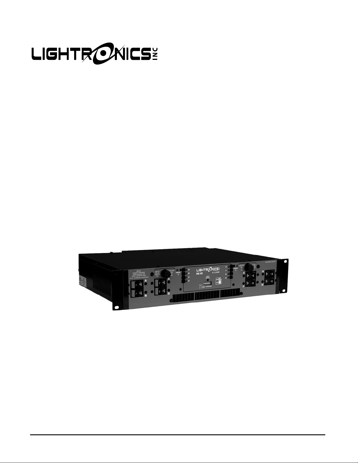
RE-82
RACK MOUNT DIMMER
8 X 2400Watts
OWNERS MANUAL
Revision 2.4
11/29/2007
www.lightronics.com
Lightronics Inc 509 Central Drive, Virginia Beach, VA 23454 TEL 757 486 3588
Page 2
Page 2 of 8
RE - 82 RACK MOUNT DIMMER
Revision 2.4 OWNERS MANUAL 11/29/2007
DESCRIPTION
The RE-82 is an 8 channel dimmer with a maximum capacity of 2,400 watts per channel giving a total of 19,200
watts. The RE-82 is controlled by a lighting console. The unit can be supplied to use either the DMX-512 control
protocol or the LMX-128 control protocol. Channels A - D and/or channels E - H may be switched to operate in
"relay" mode. In relay mode channels are either full on or full off (non-dim) depending on console fader position.
The unit is overcurrent and overtemperature protected. A fan is used to ensure proper cooling. Dimming
channels may be reassigned in multiples of 4 channels via switches in the front panel.
POWER REQUIREMENTS
Each RE-82 requires BOTH PHASES of a SINGLE PHASE 120/240 VOLT AC service or TWO PHASES of a
THREE PHASE 120/208 VOLT AC service. The neutral conductor is shared by two hots so it is important that the
two hots used are of different phases. EACH PHASE must be capable of providing 80 AMPS. Line frequency can
be either 50 or 60HZ. One or more RE-82 dimmers are to be installed into a standard 19" equipment rack with
provisions for connection to an appropriate electrical service in accordance with the National Electrical Code.
LIGHTING LOAD CAPACITY
Each RE-82 channel has a 2400 Watt MAXIMUM rating and is protected by a fast acting 20 Amp circuit breaker.
20 Amps equates to 2400 Watts at 120VAC. If you operate a channel at 2400 watts then you are very close to
tripping the breaker. This will occur if AC line voltages are high or you have power surges. Other conditi ons
which may cause the fuse to blow include turning a cold lamp quickly on to full intensity. A maximum practical
load of 2000 Watts per channel will allow for some overhead and help prevent breaker tripping.
INSTALLATION
PLACEMENT
The RE-82 is designed to be mounted in a standard 19" equipment rack using the four mounting holes in the face
plate. If the dimming system will be used for touring shows, it is recommended that you provide additional support
for the rear of the unit. The dimmer is fan cooled and requires no space between units when multiple dimmers a re
used together in a rack. Air enters the dimmer through slots on the side and exits through holes in the bottom of
the face plate. Make certain these ventilation holes are not obstructed. Do not place the RE-82 where it will be
exposed to moisture or excessive heat.
www.lightronics.com
Lightronics Inc 509 Central Drive, Virginia Beach, VA 23454 TEL 757 486 3588
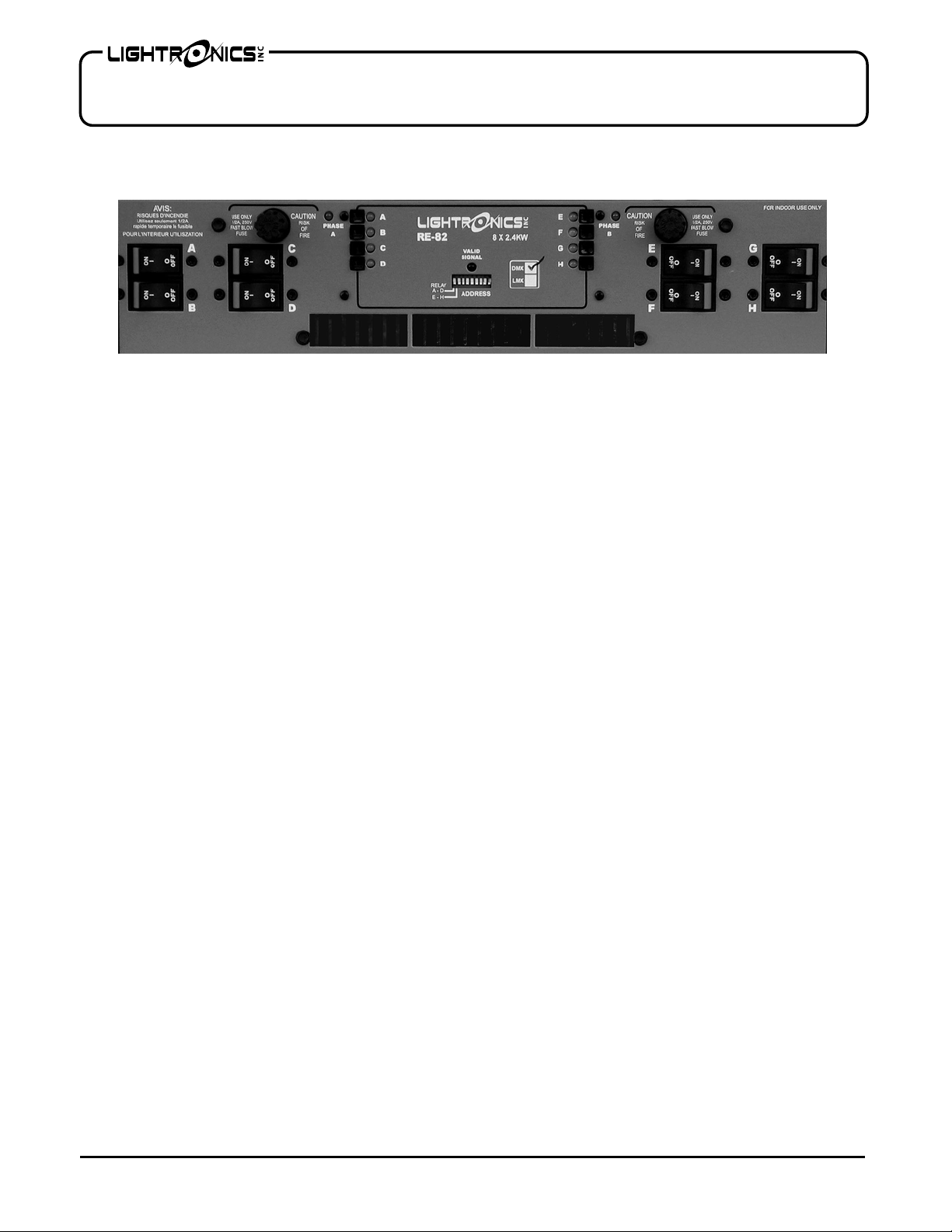
RE-82 CONTROL PANEL
Page 3

Page 3 of 8
RE - 82 RACK MOUNT DIMMER
Revision 2.4 OWNERS MANUAL 11/29/2007
POWER CONNECTIONS
MAKE CERTAIN POWER IS REMOVED FROM THE FEED CIRCUITS
BEFORE YOU BEGIN INSTALLATION.
Power enters the RE-82 through the rear of the unit via a hole sized for 1" conduit. Inside the RE-82 is a terminal
block with three lugs. The "H1" and "H2" terminals are the line connections or "hots". The center connection
labeled "N" is the neutral. There is an additional ground lug labeled "G" located near the terminal block. This lug
is for connecting the chassis to earth ground.
Consult your local electrical codes to determine the proper wire type and wiring methods for your installation.
Connect a ground wire to the ground lug "G" first. Next connect the neutral to the center lug "N" on the terminal
block, then connect one hot to the lug of the terminal block marked "H1"and the other hot to the "H2" lug of the
terminal block .
CONTROL SIGNALS
The RE-82 is supplied to use one of two types of control signal. Either DMX-512 control or LMX-128 control is
supplied when ordered. The front panel is marked to show which protocol can be used.
DMX CONTROL
The DMX-512 control signal enters the RE-82 through a 5 pin "XLR" connector on the rear of the unit. A second
connector (5 pin female XLR) is used to continue this control signal out to other dimmers in the system.
Normally the male connector is used for the incoming control signal and the female connector is used to loop out
to other dimmers. These connectors are wired in parallel so either connector may be used as input or output.
The table below shows the control signal connector pin assignments.
Connector
LMX CONTROL
The LMX-128 control signal enters the RE-82 through a 3 pin "XLR" connector on the rear of the unit. A second
connector (3 pin female XLR) is used to continue this control signal out to other dimmers in the system.
Normally the male connector is used for the incoming control signal and the female connector is used to loop out
to other dimmers. These connectors are wired in parallel so either connector may be used as input or output.
The table below shows the control signal connector pin assignments.
Connector
Pin #
1 LMX Common
2 Console Power (+15VDC)
3 LMX Signal
WARNING
Pin #
1 DMX Common
2 DMX Data 3 DMX Data +
4 Not Used
5 Not Used
Signal Name
Signal Name
www.lightronics.com
Lightronics Inc 509 Central Drive, Virginia Beach, VA 23454 TEL 757 486 3588
Page 4

Page 4 of 8
RE - 82 RACK MOUNT DIMMER
Revision 2.4 OWNERS MANUAL 11/29/2007
OUTPUT CHANNEL CONNECTIONS
The RE-82 is supplied with one of several rear panel output options. Channel output connections are according
to the the rear panel selected. Channel connections generally proceed from left to right (if you are facing the rear
of the unit). Channel “A” will be on the left end. Connections for load Neutrals are provided. There is also a
ground lug terminal to be used for your load circuits grounds.
OPERATION
CHANNEL ASSIGNMENT
The starting channel of each RE-82 is selected using the DIP switches on the front panel. The diagram below
indicates the actual value of each DIP switch position. A chart at the end of this manual "CHANNEL
ASSIGNMENT SWITCH SETTINGS" provides further information for setting the starting address DIP switches.
UP FOR RELAY MODE
Any switch in the up position ADDS the associated value to the starting channel number. All switches down =
starting channel number 1.
For example: to set the starting channel to 13, move the 2nd switch from the right (value 8) and the 1st switch
from the right (value 4) to the up position. For a starting channel of 21, move the third switch from the right (value
16) and the rightmost switch (value 4) to the up position.
MANUAL CONTROL
Dimmer channels can be activated manually by pressing corresponding button switches located on the front
panel. This will latch the associated channel to full on. Push the button again to turn the channel off. The
associated LED will light when the channel is activated.
NORMAL OPERATION
LEDs located on the front panel of the RE-82 indicate channel levels as you operate faders on your cons ole. The
"VALID SIGNAL" LED will light whenever the dimmer is receiving a control signal within the range of channels
that the dimmer is assigned to. The "Phase A" and "Phase B" LEDs will indicate that power sources are applied to
the dimmer. The fan will run continuously whenever power is applied to the RE-82. An over-temperature sensor
will shut down all channel output if the dimmer temperature rises above safe limits (≈175°F exit air temperature).
RELAY MODE
The two leftmost switches control the "relay" mode. When either switch is in the up position, the channels
associated with that switch operate in non-dim mode. These channels will be either full on or full off depending on
the level of the faders controlling them.
256 128 64 32 16 8 4
A-D E-H
ADDRESS
ON
OFF
www.lightronics.com
Lightronics Inc 509 Central Drive, Virginia Beach, VA 23454 TEL 757 486 3588
Page 5

Page 5 of 8
RE - 82 RACK MOUNT DIMMER
Revision 2.4 OWNERS MANUAL 11/29/2007
MAINTENANCE AND REPAIR
CIRCUIT BREAKERS AND FUSES
Each channel of the RE-82 is protected by a 20 Amp, fast acting, magnetic circuit breaker located on the front
panel of the unit. If the total load for a channel is greater than 2400 Watts the channel circuit breaker will trip.
There are two 1/2 Amp., 250 Volt, fast acting fuses on the front panel to protect the internal electronic circuits
from an overvoltage condition. These fuses may be replaced ONLY by fuses of the size and type given above.
TROUBLESHOOTING
VERIFY THAT ALL POWER IS REMOVED FROM THE DIMMER BEFORE HANDLING THE UNIT.
• Verify that the unit channel addresses are correctly set.
• Check that the console is powered and that console channels are correctly patched or set.
• Check the control cable between the dimmer and its console.
• Verify the loads and their connections.
OWNER MAINTENANCE
There are no user serviceable parts inside the unit.
The best way to prolong the life of your unit is to keep it cool, clean, and dry. It is important that the cooling intake
and exit vent holes are clean and unobstructed.
Service by other than Lightronics authorized agents may void your warranty.
OPERATING AND MAINTENANCE ASSISTANCE
If service is required, contact the dealer from whom you purchased the equipment or contact Lightronics, Service
Department, 509 Central Drive, Virginia Beach, VA 23454 TEL 757 486 3588 All items returned for service
must include a description of the problem along with your name address and phone number.
Lightronics recommends that you record the serial number of your unit for future reference.
SERIAL NUMBER ______________________
www.lightronics.com
Lightronics Inc 509 Central Drive, Virginia Beach, VA 23454 TEL 757 486 3588
Page 6

Page 6 of 8
RE - 82 RACK MOUNT DIMMER
Revision 2.4 OWNERS MANUAL 11/29/2007
CHANNEL ASSIGNMENT SWITCH SETTINGS
The DIP Switch Setting column shows the positions of the DIP switches on the dimmer. The Start Channel column shows the
resulting channel assignment for the first channel of the dimmer All Lightronics products using DIP switches for address
assignments conform to this table. Some dimmers cannot be set to all 512 channels and will have fewer switches than are
shown in the table. If this is the case then match the right end switches in the table to your dimmer switches.
NOTE: Some control consoles can be programmed or "patched" to alter their channel order. You may get unexpected results
if you are not aware of the console patch condition when you assign channels at a dimmer.
EXAMPLE: If a dimmer's DIP switches are set to
channel 173. The remaining dimmer channels will respond to console channels 174, 175, 176 …etc.
DIP Switch
Setting
ШШШШШШШ
ШШШШШШГ
ШШШШШГШ
ШШШШШГГ
ШШШШГШШ
ШШШШГШГ
ШШШШГГШ
ШШШШГГГ
ШШШГШШШ
ШШШГШШГ
ШШШГШГШ
ШШШГШГГ
ШШШГГШШ
ШШШГГШГ
ШШШГГГШ
ШШШГГГГ
ШШГШШШШ
ШШГШШШГ
ШШГШШГШ
ШШГШШГГ
ШШГШГШШ
ШШГШГШГ
ШШГШГГШ
ШШГШГГГ
ШШГГШШШ
ШШГГШШГ
ШШГГШГШ
ШШГГШГГ
ШШГГГШШ
ШШГГГШГ
ШШГГГГШ
ШШГГГГГ
www.lightronics.com
Lightronics Inc 509 Central Drive, Virginia Beach, VA 23454 TEL 757 486 3588
Start
Channel
1
5
9
13
17
21
25
29
33
37
41
45
49
53
57
61
65
69
73
77
81
85
89
93
97
101
105
109
113
117
121
125
DIP Switch
Setting
ШГШШШШШ
ШГШШШШГ
ШГШШШГШ
ШГШШШГГ
ШГШШГШШ
ШГШШГШГ
ШГШШГГШ
ШГШШГГГ
ШГШГШШШ
ШГШГШШГ
ШГШГШГШ
ШГШГШГГ
ШГШГГШШ
ШГШГГШГ
ШГШГГГШ
ШГШГГГГ
ШГГШШШШ
ШГГШШШГ
ШГГШШГШ
ШГГШШГГ
ШГГШГШШ
ШГГШГШГ
ШГГШГГШ
ШГГШГГГ
ШГГГШШШ
ШГГГШШГ
ШГГГШГШ
ШГГГШГГ
ШГГГГШШ
ШГГГГШГ
ШГГГГГШ
ШГГГГГГ
ШГШГШГГ then the first channel of the dimmer will respond to console
Start
Channel
129
133
137
141
145
149
153
157
161
165
169
173
177
181
185
189
193
197
201
205
209
213
217
221
225
229
233
237
241
245
249
253
DIP Switch
Setting
ГШШШШШШ
ГШШШШШГ
ГШШШШГШ
ГШШШШГГ
ГШШШГШШ
ГШШШГШГ
ГШШШГГШ
ГШШШГГГ
ГШШГШШШ
ГШШГШШГ
ГШШГШГШ
ГШШГШГГ
ГШШГГШШ
ГШШГГШГ
ГШШГГГШ
ГШШГГГГ
ГШГШШШШ
ГШГШШШГ
ГШГШШГШ
ГШГШШГГ
ГШГШГШШ
ГШГШГШГ
ГШГШГГШ
ГШГШГГГ
ГШГГШШШ
ГШГГШШГ
ГШГГШГШ
ГШГГШГГ
ГШГГГШШ
ГШГГГШГ
ГШГГГГШ
ГШГГГГГ
Start
Channel
257
261
265
269
273
277
281
285
289
293
297
301
305
309
313
317
321
325
329
333
337
341
345
349
353
357
361
365
369
373
377
381
DIP Switch
Setting
ГГШШШШШ
ГГШШШШГ
ГГШШШГШ
ГГШШШГГ
ГГШШГШШ
ГГШШГШГ
ГГШШГГШ
ГГШШГГГ
ГГШГШШШ
ГГШГШШГ
ГГШГШГШ
ГГШГШГГ
ГГШГГШШ
ГГШГГШГ
ГГШГГГШ
ГГШГГГГ
ГГГШШШШ
ГГГШШШГ
ГГГШШГШ
ГГГШШГГ
ГГГШГШШ
ГГГШГШГ
ГГГШГГШ
ГГГШГГГ
ГГГГШШШ
ГГГГШШГ
ГГГГШГШ
ГГГГШГГ
ГГГГГШШ
ГГГГГШГ
ГГГГГГШ
ГГГГГГГ
Start
Channel
385
389
393
397
401
405
409
413
417
421
425
429
433
437
441
445
449
453
457
461
465
469
473
477
481
485
489
493
497
501
505
509
Page 7
W
Y
All Lightronics products are warranted for a period of TWO/FIVE YEARS from the date of
purchase against defects in materials and workmanship.
This warranty is subject to the following restrictions and conditions:
A) If service is required, you may be asked to provide proof of purchase from an authorized
Lightronics dealer.
B) The FIVE YEAR WARRANTY is only valid if the warranty card is returned to Lightronics
accompanied with a copy of the original receipt of purchase within 30 DAYS of the
purchase date, if not then the TWO YEAR WARRANTY applies. Warranty is valid only for
the original purchaser of the unit.
C) This warranty does not apply to damage resulting from abuse, misuse, accidents, shipping,
and repairs or modifications by anyone other than an authorized Lightronics service
representative.
D) This warranty is void if the serial number is removed, altered or defaced.
E) This warranty does not cover loss or damage, direct or indirect arising from the use or
inability to use this product.
F) Lightronics reserves the right to make any changes, modifications, or updates as deemed
appropriate by Lightronics to products returned for service. Such changes may be made
without prior notification to the user and without incurring any responsibility or liability for
modifications or changes to equipment previously supplied. Lightronics is not responsible
for supplying new equipment in accordance with any earlier specifications.
G) This warranty is the only warranty either expressed, implied, or statutory, upon which the
equipment is purchased. No representatives, dealers or any of their agents are authorized
to make any warranties, guarantees, or representations other than expressly stated herein.
H) This warranty does not cover the cost of shipping products to or from Lightronics for
service.
I) Lightronics Inc. reserves the right to make changes as deemed necessary to this warranty
without prior notification.
Lightronics Inc. 509 Central Drive Virginia Beach, VA 23454 20050125
ARRANT
Page 8

www.lightronics.com
Lightronics Inc 509 Central Drive, Virginia Beach, VA 23454 TEL 757 486 3588
 Loading...