

Page 1
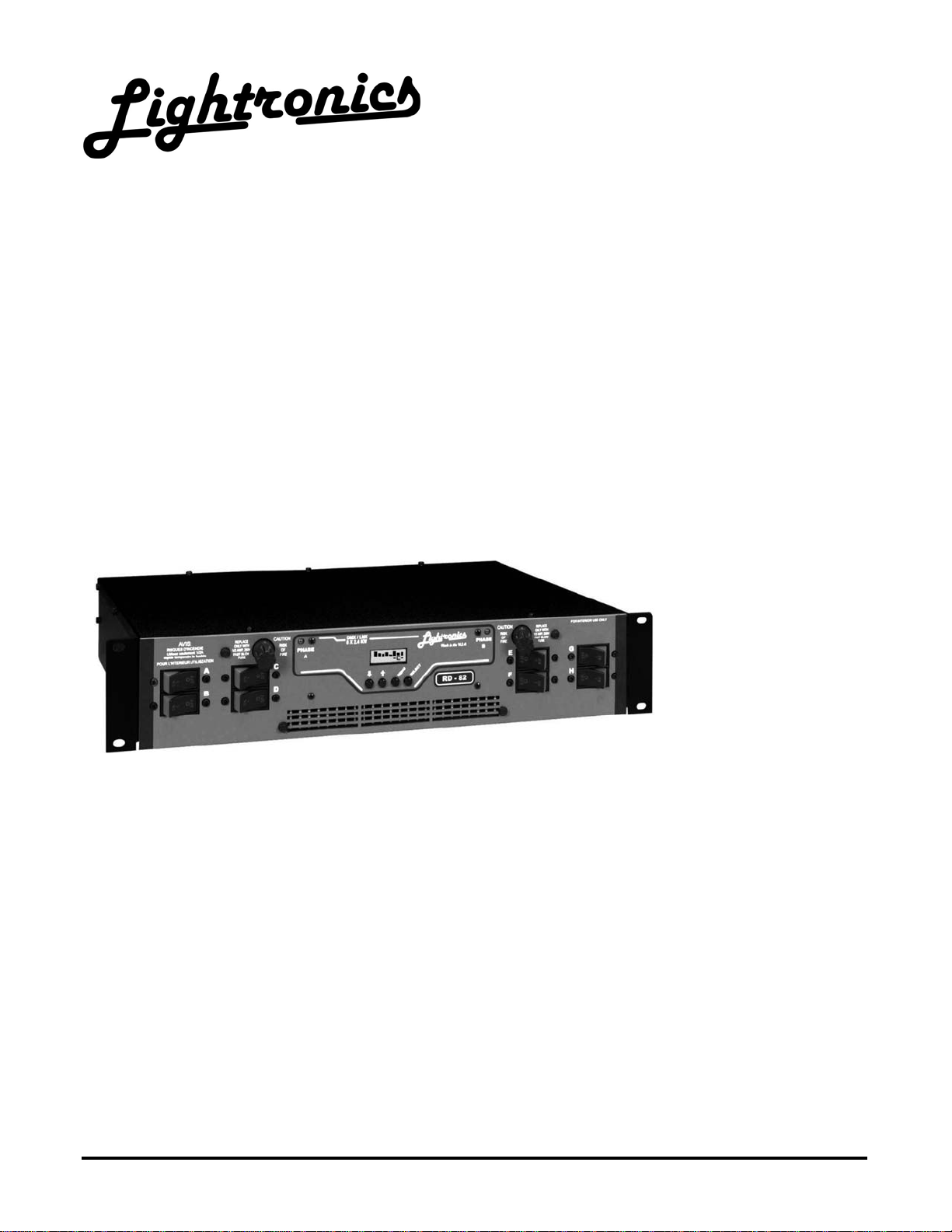
RD - 82
RACK MOUNT DIMMER
OWNERS MANUAL
REVISION 1.2
02/28/2005
www.lightronics.com
Lightronics Inc. 509 Central Drive, Virginia Beach, VA 23454 (757) 486-3588
Page 2

Page 2 of 14
RD - 82 RACK MOUNT DIMMER
Version 1.2 OWNERS MANUAL 02/28/2005
TABLE OF CONTENTS
UNIT DESCRIPTION AND FUNCTIONS 3
POWER REQUIREMENTS 3
INSTALLATION 3
PLACEMENT 3
POWER CONNECTIONS 3
OUTPUT CHANNEL CONNECTIONS 4
CONTROL SIGNAL CONNECTIONS 4
SETUP 4
STATUS DISPLAY AND OPERATOR CONTROLS 4
RESETTING THE UNIT 5
ASSIGNING DIMMER CHANNELS 5
TO SET CHANNELS TO DIM OR NON-DIM 5
MANUAL OPERATION 5
NORMAL OPERATION 6
INTERNAL SCENE OPERATION 6
TO SAVE A SCENE 6
TO ACTIVATE A STORED SCENE 6
NOTES ABOUT INTERNAL SCENE 7
CHASER OPERATION 7
ACTIVATING A CHASE PATTERN 7
SELECTING A CHASE PATTERN 7
CONTROLLING CHASER CHARACTERISTICS 8
STRUCTURE OF THE MENU SYSTEM 9
CREATING YOUR OWN CUSTOM CHASE PATTERN 10
TO SAVE A CHASE STEP 10
MAINTENANCE AND REPAIR 11
TROUBLESHOOTING 11
OWNER MAINTENANCE 11
OPERATING AND MAINTENANCE ASSISTANCE 11
MULTIPLEX CONNECTIONS - DIAGRAM 12
DMX-512 CONNECTIONS - DIAGRAM 12
PIN ASSIGNMENTS OF CONTROL SIGNAL CONNECTORS 13
www.lightronics.com
Lightronics Inc. 509 Central Drive, Virginia Beach, VA 23454 (757) 486-3588
Page 3
Page 3 of 14
RD - 82 RACK MOUNT DIMMER
Version 1.2 OWNERS MANUAL 02/28/2005
UNIT DESCRIPTION AND FUNCTIONS
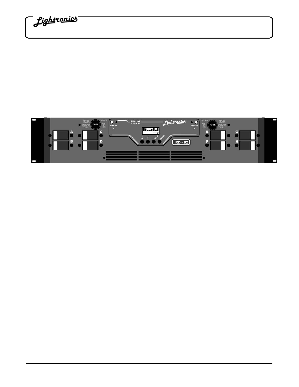
The RD-82 is a 19,200 Watt, 8 channel, rack mountable lighting dimmer. Each of the channels has a capacity of
2400 Watts. It is controlled via low voltage signals which may be LMX-128 (3 wire multiplex), or USITT DMX-512.
The unit is fan cooled. Channels may be independently assigned from the unit. The unit is over temperature and
over voltage protected and has a magnetic circuit breaker for each channel. There are several options for
channel output connection panels. Options include: Edison plug, Knockout panel with internal terminal strip,
External Terminal Strip, Patch panel, Stage pin panel, and Socapex Connector panel. The RD-82 also has
several "stand alone functions" which enable it to operate without a control console. These functions include a
storable scene which may be activated by an external switch closure, a programmable chaser, and 7 factory set
chase patterns.
POWER REQUIREMENTS
Each RD-82 requires SINGLE PHASE 240 VOLT AC or TWO PHASES OF A THREE PHASE 120/208 VOLT AC
service. The neutral conductor is shared by two hots so it is important that the two hots used are of different
phases. EACH PHASE must be capable of providing 80 AMPS. Line frequency is typically 60HZ. A 50HZ model
is available for export. Refer to the electrical rating markings on the dimmer to determine the operating
frequency. One or more RD-82 dimmers are to be installed into a standard 19" equipment rack with provisions for
connection to an appropriate electrical service in accordance with the National Electrical Code.
INSTALLATION
PLACEMENT
The RD-82 is designed to be mounted in a standard 19" equipment rack using the four mounting holes in the face
plate of the dimmer. If the dimming system will be used for touring shows, it is recommended that you provide
additional support for the rear of the unit. The dimmer is fan cooled and requires no space between units when
multiple dimmers are used. Air enters the dimmer through slots on the side and exits through holes in the bottom
of the face plate. Make certain these ventilation holes are not obstructed. Do not place the RD-82 where it will be
exposed to moisture or excessive heat.
POWER CONNECTIONS
Make certain power is removed from the circuits before you begin installation of the dimmer. Consult your
local electrical codes to determine the proper wire type and wiring methods for your installatio n.
Power enters the RD-82 through a knockout sized hole at the rear of the unit. Remove the top cover and install
an appropriate cable clamp in the knockout hole. Pass the power cables through the hole. Behind the hole is a
terminal block with three lugs. The connections labeled "H1" and "H2" are the line or "hots". The center
connection labeled "N" is the neutral. There is an additional lug labeled "G" to the right of the terminal block. This
is for connecting the unit to earth ground. When connections are completed, reinstall the cover and tighten the
cable clamp.
www.lightronics.com
Lightronics Inc. 509 Central Drive, Virginia Beach, VA 23454 (757) 486-3588
The RD-82 is intended for INDOOR USE ONLY.
Page 4
Page 4 of 14
RD - 82 RACK MOUNT DIMMER
Version 1.2 OWNERS MANUAL 02/28/2005
OUTPUT CHANNEL CONNECTIONS
The RD-82 can be supplied with one of several rear panel output options. Channel output connections are
according to the the rear panel selected. Channel connections generally proceed from left to right (if you are
facing the rear of the unit). Channel “A” will be on the left end. Connections for load Neutrals are provided. There
is also a ground lug terminal to be used for your load circuits grounds.
CONTROL SIGNAL CONNECTIONS
A control signal enters the RD-82 through connectors on the rear of the unit. If you are using the 3 pin multiplex
protocol ("LMX" or compatible), plug the control cable into the 3 pin "XLR" connector. If you are using the DMX512 protocol, plug your 5 pin DMX control cable into the 5 pin to 9 pin adapter supplied with the RD-82 and plug
the 9 pin connector into the upper 9 pin connector on the rear of the dimmer. In either case, the lower 9 pin
connector and the ribbon cable jumper that is supplied can be used to connect from the lower connecto r of the
first dimmer into the upper connector of the next dimmer and so on. See the included drawings at the back of this
manual for clarification. The RD-82 is shipped with the power supply set to provide +15 volts DC console power
when using the 3 pin multiplex protocol. Note that the DMX-512 protocol does NOT provide a means for console
power via the control cable. Systems using the DMX protocol must have console power supplied by other means.
SETUP
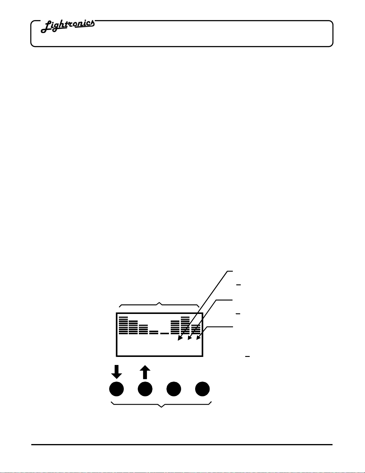
The RD-82 has a front panel LCD display and operator controls. The display indicates dimmer status information
and is used with the operator control buttons to set up and monitor dimmer operation. A menu system is used to
access the various features of the RD-82. During normal dimmer operation the display shows the current
intensity setting for each channel and indicates what type of dimmer control is in affect. This is called the
STATUS DISPLAY and is shown in the diagram below.
STATUS DISPLAY AND OPERATOR CONTROLS
CHASER INDICATOR
C = Chaser Active
CHANNEL LEVEL
BARGRAPHS
CSD
CT
SE
E
L
NU
E
M
OPERATOR CONTROL BUTTONS
www.lightronics.com
Lightronics Inc. 509 Central Drive, Virginia Beach, VA 23454 (757) 486-3588
= Chaser Off
SCENE INDICATOR
S = Scene Active
= Scene Off
CONTROL SIGNAL
INDICATOR
D = DMX
L = LMX
= No Signal
Page 5

Page 5 of 14
RD - 82 RACK MOUNT DIMMER
Version 1.2 OWNERS MANUAL 02/28/2005
RESETTING THE UNIT
The RD-82 may be reset to a "factory provided" configuration by holding down the MENU button on the front
panel for about 5 seconds. A message "SYSTEM RESET" will appear on the front panel LCD display. Release
the MENU button when you see the message. Resetting the unit causes the following actions:
1. Channel patch is set to 1 to 1.
2. All channels are set to to DIM (relay mode turned off).
3. The external switch sensing function is turned off.
4. The internally stored scene is turned off. (it is not erased).
5. The programmable chase pattern is turned off and erased.
6. Chase parameters are set to a default set of conditions. The Default conditions are given in the table under
the section CONTROLLING CHASER CHARACTERISTICS.
You should perform a setup procedure before using the unit. Setup includes (1) Setting the channel assignments
that the dimmer will respond to and (2) Setting individual channels to “DIM” or “NON-DIM” (relay). Once the
setup is completed the unit will retain the settings until changed by the operator (includin g when the unit is
powered off and restarted).
ASSIGNING DIMMER CHANNELS (CHANNEL PATCHING)
The RD-82 has eight dimming channels labeled A-H. Each of these channels may be assigned to any con sole
channel number from 1 to 512. Multiple dimmer channels may be assigned to a single console fader if desired.
This gives you the ability to soft patch at the dimmer itself.
TO ASSIGN DIMMER CHANNELS:
1. Press the MENU once to enter the patch mode. The display will indicate “PTCH”.
2. Push SELECT. The left display bargraph channel (for dimmer channel A) will flash and the currently
assigned console channel will be shown on the display bottom row. Use the UP and DOWN arrow buttons to
change the console channel assignment for channel A.
3. Push SELECT to advance to the next dimmer channel. Continue to assign channels through channel H.
4. Push MENU three times to return to the normal operation mode.
TO SET CHANNELS TO DIM OR NON-DIM (RELAY):
1. Press MENU twice. The LCD display will indicate “NDIM”.
2. Push SELECT. The left display bargraph channel (for dimmer channel A) will flash. The display will show
“DMR” or “RLY” on the bottom row according to the current setting.
3. Use the UP and DOWN arrow buttons to change between dim and relay modes for that channel.
4. Push SELECT to advance to the next dimmer channel. Continue to set channels through channel H.
5. Press MENU twice to return to the normal display.
MANUAL OPERATION
Dimmer channels can be operated manually from the dimmer front panel. Press the SELECT button until the
desired channel's "bar graph" is flashing. Press the UP or DOWN arrow buttons until the desired level is reached.
Press the SELECT button to advance to other channels. To return control to your console, press the SELECT
button until you go PAST the last channel and stop. After approximately 6 seconds the dimmer will return to
console control. A channel continues to respond to console settings when operating from the front panel unless
you change the level for
that channel at the dimmer front panel. Once this occurs - that channel will NOT respond to console settings until
you return to normal console control.
www.lightronics.com
Lightronics Inc. 509 Central Drive, Virginia Beach, VA 23454 (757) 486-3588
Page 6

Page 6 of 14
RD - 82 RACK MOUNT DIMMER
Version 1.2 OWNERS MANUAL 02/28/2005
NORMAL OPERATION
As you operate faders on your console the associated channel levels are indicated on the RD-82 display. The
display will also indicate any abnormal conditions such as over temperature or over voltage. The fan will run at full
speed whenever there is a control signal present and one or more faders are at full on. The fan will drop to half
speed a few minutes after all faders are lowered to full off and will stop shortly after the control signal is removed.
INTERNAL SCENE OPERATION
The RD-82 has the ability to internally save a single scene which may be activated remotely. The scene remains
in the unit’s memory when it is shut off and will be available the next time the unit is powered on. A saved scene
is not lost when the unit is reset.
TO SAVE A SCENE:
1. Create the scene from a control console or from the front panel of the dimmer itself by activating the
applicable channels.
2. Press and hold the front panel SELECT button until the front panel display appears as sho wn below:
You will have to hold the button down for about 6 second s.
3. Push SELECT. The display will show the message:
4. The scene has been recorded when the LCD reverts to its normal display.
TO ACTIVATE A STORED SCENE:
A scene previously stored in the RD-82 is activated by connecting together pins 5 and 9 of either DB9 connector.
The DB9 connectors are on the rear of the dimmer. This may be done via a remotely located switch. The
activated scene will remain active as long as pins 5 and 9 on the DB9 connectors remain connected together.
In addition to activating a scene, the RD-82 can be set to ignore the remote switch or activate chaser functions. In
order to use the remote switch for internal scene activation you must enable that function as follows:
1. Push MENU 3 times. The display will show the message "MENU" on the bottom row.
2. Push SELECT. The LCD will display one of messages shown below.
Scene ×
Save #01
SAVING
NOW !
Input1 ×
Scene
3. If "Not Used" or "Chaser" appears on the bottom row, push the UP or DOWN arrow buttons until "Scene"
appears.
4. Push SELECT to return the unit to normal operation.
The front panel display shows an "S" on the bottom row as an indication that an internal scene is active.
www.lightronics.com
Lightronics Inc. 509 Central Drive, Virginia Beach, VA 23454 (757) 486-3588
Input1 ×
Chaser
Input1 ×
Not Used
Page 7

Page 7 of 14
RD - 82 RACK MOUNT DIMMER
Version 1.2 OWNERS MANUAL 02/28/2005
NOTES ABOUT INTERNAL SCENE:
The RD-82 continues to respond to control console signals when the internal scene is activated. The intensity of
any given channel will be the "greatest of" or "pile on" result of the internal scene and console level setting.
If multiple Lightronics RD series dimmers are connected as a system (See CONTROL SIGNAL CONNECTIONS),
then a remote switch connected to the system can activate system wide scenes or only scenes in specific
dimmers depending on how the remote switch function is set in each dimmer. These scene features give you the
ability to use the dimmer for house lights and other applications where is is not practical to operate a control
console.
CHASER OPERATION
The RD-82 can operate chaser functions as a "stand alone" unit with no control console present. There are 7
factory set chase patterns embedded in the unit software. There is also one pattern which may be programmed
by the user. The chase step rate, chase step fade rate, and chase intensity can be set by the user for all chaser
functions. Chaser functions may be set to run continuously or as a single occurance. The number of steps (up to
32) can be set for the programmable chase. The RD-82 may be set to begin chaser functions at "power up" or in
response to a remote switch. A bounce option can be imposed on a chase pattern. This results in a pattern which
runs in its normal sequence then runs the same sequence backwards.
ACTIVATING A CHASE PATTERN
A chase stored in the RD-82 is activated by connecting together pins 5 and 9 of either DB9 connector. The DB9
connectors are on the rear of the dimmer. This may be done via a remotely located switch. The activated chase
will remain active as long as pins 5 and 9 on the DB9 connectors remain connected together.
In addition to activating a chase, the RD-82 can be set to ignore the remote switch or activate a scene. In order to
use the remote switch to activate chase patterns you must enable that function as follows:
1. Push MENU 3 times. The display will show the message "MENU" on the bottom row.
2. Push SELECT. The LCD will display one of messages shown below.
Input1 ×
Chaser
3. If "Not Used" or "Scene" appears on the bottom row, push the UP or DOWN arrow buttons unt il "Chaser"
appears.
4. Push SELECT to return the unit to normal operation.
The Front panel display shows a "C" on the bottom row as an indication that an internal chase is active.
SELECTING A CHASE PATTERN
You can select any of the 7 factory preset chase patterns to run or create and run your own custom pattern.
Instructions for creating a custom chase pattern are given further on in this manual.
A chase pattern is selected using the RD-82 menu system as follows:
www.lightronics.com
Lightronics Inc. 509 Central Drive, Virginia Beach, VA 23454 (757) 486-3588
Input1 ×
Scene
Input1 ×
Not Used
Page 8

Page 8 of 14
RD - 82 RACK MOUNT DIMMER
Version 1.2 OWNERS MANUAL 02/28/2005
1. Push MENU 3 times. The LCD will appear as shown:
2. Push SELECT. Then push MENU. The LCD will appear as shown: The bottom
display row shows the currently selected pattern. The pattern "4Ch Seq" is
shown as an example.
3. Use the UP and DOWN arrow buttons to scroll through the available chase
patterns. Push SELECT when the desired pattern appears.
Note: Remember that this action does not activate the chase pattern. The action selects which pattern will be
run when activated by the remote switch function.
The available patterns are:
4 CHANNEL SEQUENCE 8 CHANNEL SEQUENCE
4 CHANNEL BUILD 12 CHANNEL SEQUENCE
6 CHANNEL SEQUENCE RANDOM
6 CHANNEL BUILD PROGRAMMABLE
CONTROLLING CHASER CHARACTERISTICS
You can control seven characteristics of a chase pattern. These controls are d escribed as follows:
Chase Rate
Chase Fade Rate
Chase Intensity
Chase Steps
Chase Bounce
Continuous /Single
Activate Chase at power up
** Overrides remote switch setting
The default setting is the factory set value.
All of these characteristics can be set via the RD-82 menu system. See the diagram STRUCTURE OF MENU
SYSTEM for a complete layout of menu system operation.
www.lightronics.com
Lightronics Inc. 509 Central Drive, Virginia Beach, VA 23454 (757) 486-3588
The duration of each chase step (.25 - 999.75 Sec.).
Default = 1 Sec.
The time for each step to reach maximum intensity (0 - 100% of step time).
Default = 100%
The overall brightness of the chase (0 - 100%)
Default = 100%
The maximum number of steps in the chase (1 - 32)
Default = 4
Causes reversal at the end of each sequence (Ignored during RANDOM).
Default = Off
Enables/Disables a "one shot" chase occurance (Ignored during RANDOM).
Default = Continuous
Enables chase to begin automatically when dimmer is turned on. **
Default = Off
MENU
Chase# ×
4Ch Seq
Page 9

Page 9 of 14
_
STATUS DISPLAY
RD - 82 RACK MOUNT DIMMER
Version 1.2 OWNERS MANUAL 02/28/2005
STRUCTURE OF MENU SYSTEM
www.lightronics.com
Lightronics Inc. 509 Central Drive, Virginia Beach, VA 23454 (757) 486-3588
MENU
MENU
MENU
MENU
D
PTCH
NDIM
MENU
SELECT
SELECT
SELECT
SELECT
MENU
001
MENU
DMR
MENU
Input1
Not Used
MENU
Chase#
4Ch Seq
MENU
ChsRate
001
Sec
MENU
ChsFade
FL%
MENU
ChsInt
FL%
MENU
ChsStps
16 Steps
MENU
ChsBnce
Normal
MENU
ChsMode
Normal
MENU
ChsPwr
Normal
MENU
= Raise/Lower Intensity of Flashing Channel
SELECT = Advance to Next Cha nnel
D
= Assign Console Channel to Flashing Dimmer Channel
SELECT = Advance to Next Cha nnel
= Set Flashing Channel to Relay/Dimmer Mode
(RLY = Relay Mode, DMR = Dimmer Mode)
SELECT = Advance to Next Cha nnel
= Set Remote Switch Function (Not Used/Chaser/Scene)
SELECT = Exit
= Set Chase P a tte r n (4Ch Se q, 4 C h B u ild , 6 C h Se q ,
6 Ch Build, 8Ch Seq, 12 Ch Seq, Random, Program)
SELECT =Exit
= Set Chase Rate (.25 - 999.75 Sec. per step)
SELECT = Exit
= Set Chase Fade Rate (0 - 100% of step time)
FL% = 100%
SELECT = Exit
= Set Chase In te nsity (0 - 100 %)
FL% = 100%
SELECT = Exit
= Set Chase Max Steps (1 - 32)
SELECT = Exit
= Set Chase Bounce (Normal = OFF, Bounce = ON)
SELECT = Exit
= Set Chase run Normal/Single (Normal = Continuous)
SELECT = Exit
= Set Chase at Po w e r Up (N or mal = OF F, PwrU p - ON )
SELECT = Exit
Page 10

Page 10 of 14
RD - 82 RACK MOUNT DIMMER
Version 1.2 OWNERS MANUAL 02/28/2005
CREATING YOUR OWN CUSTOM CHASE PATTERN
The programmable chase pattern is created by setting the intensity for all dimmer channels for each step in the
chase. The chase step is then recorded. This action is then repeated for each additional step to be recorded.
The channel intensities can be set either from the RD-82 front panel as in manual operation or by using a co ntrol
console.
TO SAVE A CHASE STEP:
1. Create the step from a control console or from the front panel of the dimmer itself by activating the
applicable ch annels. Channel intensities are recorded as either full ON or full OFF. If you want a given
channel to be on for a chase step then the channel must be set to greater than 50 % intensity. Note that the
overall intensity of the whole chase pattern may be set using the menu system.
2. Press and hold the front panel SELECT button until the front panel display appears as sho wn below:
You will have to hold the button down for about 6 second s.
3. Push the UP arrow button. The display will appear as follows:
This is the display for chase step #1. If you want to record to
another step number - use the UP and DOWN arrow buttons to
make the correct step number appear on the lower display row.
4. Push SELECT. The display will show the message:
5. The chase step has been recorded when the LCD reverts to its normal STATUS DISPLAY.
The above recording process is repeated for each step in the programmable cha se patte rn. See the section
CONTROLLING CHASER CHARACTERISTICS for information about how the chase can be made to appear
when activated.
Scene ×
Save #01
Chs Stp×
Save #01
SAVING
NOW !
www.lightronics.com
Lightronics Inc. 509 Central Drive, Virginia Beach, VA 23454 (757) 486-3588
Page 11

Page 11 of 14
RD - 82 RACK MOUNT DIMMER
Version 1.2 OWNERS MANUAL 02/28/2005
MAINTENANCE AND REPAIR
TROUBLESHOOTING
VERIFY THAT ALL POWER IS REMOVED FROM THE DIMMER BEFORE HANDLING THE UNIT.
• To simplify troubleshooting - reset the unit to provide a known set of conditions.
• Check that the console is powered and that console channels are correctly patched or set.
• Check the control cable between the dimmer and its console.
• Verify the loads and their connections.
OWNER MAINTENANCE
There are no user serviceable parts inside the unit.
The best way to prolong the life of your unit is to keep is cool, clean, and dry. It is important that the cooling
intake and exit vent holes are clean and unobstructed.
Service by other than Lightronics authorized agents may void your warranty.
OPERATING AND MAINTENANCE ASSISTANCE
If service is required, contact the dealer from whom you purchased the equipment or contact Lightronics, Service
Department, 509 Central Drive, Virginia Beach, VA 23454 TEL 757 486 3588.
Lightronics recommends that you record the serial number of your unit for future reference.
SERIAL NUMBER
______________________
www.lightronics.com
Lightronics Inc. 509 Central Drive, Virginia Beach, VA 23454 (757) 486-3588
Page 12

Page 12 of 14
CO
S
ts
RD - 82 RACK MOUNT DIMMER
Version 1.2 OWNERS MANUAL 02/28/2005
MULTIPLEX
DMX-512 CONNECTIONS
DIMMER
DIMMER
NNECTION
Console using 3 pin
multiplex protocol
3 Wire Control Cable
3 Pin Multiplex
Prot ocol Inp ut
Ribbon Cable Jumper
Supplied with each unit
To other units
Console using
DMX-512 protocol
DMX Control Cable
with 5 pin XLR connectors
(SHIELDED data cable)
DIMMER
DMX-512 protocol
5 pin to 9 pin adapter
Supplied with each unit
DIMMER
Ribbon Cable Jumper
Supplied with each unit
To other uni
www.lightronics.com
Lightronics Inc. 509 Central Drive, Virginia Beach, VA 23454 (757) 486-3588
Page 13

Page 13 of 14
RD - 82 RACK MOUNT DIMMER
Version 1.2 OWNERS MANUAL 02/28/2005
PIN ASSIGNMENTS OF CONNECTORS USED WITH THE RD-82 AND RD-121
MULTIPLEX ( LMX) CONNECTOR
3 PIN MALE XLR
Used on rear of chassis
COMMON
COMMON
1
2
3
CONSOLE
POWER
LMX-128
SIGNAL
I/O CONNECTOR
9 PIN MALE (DB9)
Used on rear of chassis
LMX
COMMON
LMX
CONSOLE
POWER
12
LMX-128
SIGNAL
345
DMX
COMMON
6
789
DMX
DATA -
DMX
DATA +
DMX-512 CONNECTOR
5 PIN MALE XLR
Used on adapter cable
1
5
2
4
3
DMX
DATA -
DMX
DATA +
REMOTE SWITCH
COMMON
REMOTE SWITCH
INPUT
NOT USED
NOT USED
www.lightronics.com
Lightronics Inc. 509 Central Drive, Virginia Beach, VA 23454 (757) 486-3588
Page 14

WARRANTY
All Lightronics products are warranted for a period of TWO/FIVE YEARS from the date of
purchase against defects in materials and workmanship.
This warranty is subject to the following restrictions and conditions:
A) If service is required, you may be asked to provide proof of purchase from an authorized
Lightronics dealer.
B) The FIVE YEAR WARRANTY is only valid if the warranty card is returned to Lightronics
accompanied with a copy of the original receipt of purchase within 30 DAYS of the
purchase date, if not then the TWO YEAR WARRANTY applies. Warranty is valid only for
the original purchaser of the unit.
C) This warranty does not apply to damage resulting from abuse, misuse, accidents, shipping,
and repairs or modifications by anyone other than an authorized Lightronics service
representative.
D) This warranty is void if the serial number is removed, altered or defaced.
E) This warranty does not cover loss or damage, direct or indirect arising from the use or
inability to use this product.
F) Lightronics reserves the right to make any changes, modifications, or updates as deemed
appropriate by Lightronics to products returned for service. Such changes may be made
without prior notification to the user and without incurring any responsibility or liability for
modifications or changes to equipment previously supplied. Lightronics is not responsible
for supplying new equipment in accordance with any earlier specifications.
G) This warranty is the only warranty either expressed, implied, or statutory, upon which the
equipment is purchased. No representatives, dealers or any of their agents are authorized
to make any warranties, guarantees, or representations other than expressly stated herein.
H) This warranty does not cover the cost of shipping products to or from Lightronics for
service.
I) Lightronics Inc. reserves the right to make changes as deemed necessary to this warranty
without prior notification.
Lightronics Inc. 509 Central Drive Virginia Beach, VA 23454 20050125
 Loading...