

Page 1
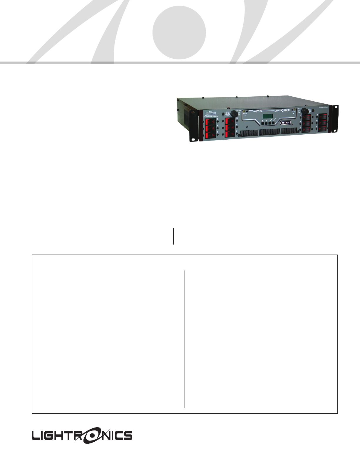
Rack Mounted Dimmers
• 12 Channels
• 1200 Watts per Channel
• Remote Activated Scene
• DMX-512 and LMX-128 Control
• UL-508 Compliant
• Stand Alone Chaser Functions
The RD-121 multi-protocol dimmer features softpatch, remote activated internal scene and advanced
chase functions that enable it to provide stand alone operation. Softpatching allows any dimmer
channel to be assigned to any incoming control channel. An internal scene provides the ability to
activate general lighting from each entrance way with remote switches. The slow chase feature
allows gradual lighting changers for visual architectural variety. Each dimmer channel may be
individually selected for dimmer or relay mode. High quality semiconductors, over-voltage,
over-current, and over-temperature protection provide the reliability and condence you expect.
CHANNEL OUTPUT CONNECTIONS OPTIONS
Duplex outlet panel with 2 connections per channel
External terminal strip (includes knockout cover)
Stagepin panel with 1 connection per channel
Patchbay panel with 4 powerlock connections per channel
Socapex connector panel (wiring per customer selection)
Rack Mount Dimmer
RD-121
SPECIFICATIONS
Channels/Capacity: 12 @ 1200 Watts each
Power Input: 2 HOTS of 120VAC Single/Three
Phase 60 Amps per Hot Input
Under Full Load
Overload Protection: 10 Amp Fast Acting Circuit
Breakers
System Addressability: Softpatch any dimmer channel
to any control channel
Cooling: Variable speed fan with auto
shutdown
Filtering: 350 Microseconds Minimum
Rise Time
Relay Mode: Each individual channel may be
set for relay mode
Minimum Load: 15 Watts
509 Central Dr., Virginia Beach, VA 23454. Tel: 757-486-3588 / 800-472-8541.
Fax: 757-486-3391. Visit us online at www.lightronics.com. 101213smh
Display: Dimmer Levels, Scene/Chase/Control
Signal Status and Setup Menus
Control Sources: DMX-512, LMX-128
Local Control: Dimmers may be adjusted without
a console
Internal Scene: Level memory with 2 second fade
rate, pile-on mode
Remote Switch: Scene ON/OFF, Chase ON/OFF, or
Not Used
Chase Patterns: 7 Preset, 1 User Programmable
Chase Steps: 32 Maximum
Step Rates: 1/4 Second Increments, 1/4 Second
to 16 1/2 Minutes
Size: 19”W x 3.5”H x 13”D
Weight: 27 Pounds
Page 2

DUPLEX OUTLET PANEL
CHANNEL OUTPUT CONNECTIONS
1 2
3
4
5
6
7
8 9 10
11
12
LMX CONTROL IN
DMX + OTHER CONTROLS
INPUT
POWER
ACCESS
EXTERNAL TERMINAL STRIP (includes knockout cover)
GROUND
LMX CONTROL IN
1 2
3
4
5
6 7 8 9 10
1211
CHANNEL OUTPUT CONNECTIONS
CHANNEL
NEUTRALS
DMX + OTHER CONTROLS
INPUT
POWER
ACCESS
STAGE PIN PANEL
CHANNEL OUTPUT CONNECTIONS
1 2
3
4
5 6
7
8 9 10
11 12
LMX CONTROL IN
DMX + OTHER CONTROLS
INPUT
POWER
ACCESS
PATCH BAY PANEL
CHAN.
NEUTRALS
1
2
3
4
5 6
7
8
9
10 11
12
LMX CONTROL IN
DMX + OTHER CONTROLS
GROUND
CHANNEL OUTPUT TERMINALS
INPUT
POWER
ACCESS
SOCAPEX PANEL
OUTPUT CHANNELS CONNECTORS (19 pin)
LMX CONTROL IN
DMX + OTHER CONTROLS
1
2
3
4
5
6
7
8
9
10
11
12
13
14
15
16
17
18
19
1
2
3
4
5
6
7
8
9
10
11
12
13
14
15
16
17
18
19
INPUT
POWER
ACCESS
Architect & Engineer’s Specications
The dimming system shall have 12
circuits with a load capacity of 1200 Watts
per circuit. Each circuit is protected by
a 10 Amp fast acting magnetic circuit
breaker. An allowance of 200% overhead
capacity is employed in the circuit design.
The dimming system shall have a rise time
of not less than 350 microseconds.
Programming setup and memory
attributes is via a front panel LCD display
with keypad controls. A user may
program the system setup, dimmer
attributes of Dim or Relay, Softpatch, a
single scene memory and a chase via the
front panel display and keypad controls.
There are seven preset chases and one
user programmable chase, a maximum of
32 steps are available in the chase, chase
steps are programmable in 1/4 Sec.
increments, 1/4 sec to 16 1/2 Minutes in
length. The single scene and chase on/off
are recalled via contact closure. The
dimming system uses the USITT standard
DMX-512 protocol and LMX-128 protocol
for direct control of the dimming circuits.
Power requirements of the dimming
system shall be 2 hots of 120VAC
Single/Three phase service. Capacity shall
be 60 Amps per leg. DMX-512 and contact
closure are connected through a standard
DB9 connector, a ribbon connector is used
to pass data to subsequent RD series
dimmers. A variety of electrical output
connections are available including
Stage Pin, Socapex, Patch Bay
(Powerlock), Duplex (Edison) and External
Terminal Strip. Mounting of the dimming
system shall be on standard 19” EIA rack
mount. All components and sub-systems
of the dimming system shall be UL
recognized and conform to the standards
set forth. Dimensions are 3.5”H x 19”W x
13”D and the weight shall be 27 lbs. The
Dimming System is covered by a 5 year
factory warranty.
The 5 year warranty is valid if the Warranty Registration
card is returned to Light ronics, Inc. within 30 DAYS of
5 YE AR WA RR AN TY
the purchase date.
509 Central Dr., Virginia Beach, VA 23454. Tel: 757-486-3588 / 800-472-8541.
Fax: 757-486-3391. Visit us online at www.lightronics.com. 101213smh
The dimming system shall be a
Lightronics RD-121.
 Loading...