

Page 1
PIN #
SIGNAL NAME
1
DMX COMMON
2
DMX DATA -
3
DMX DATA +
CAUTION
RISK OF ELECTRIC SHOCK
Page 1 of 4
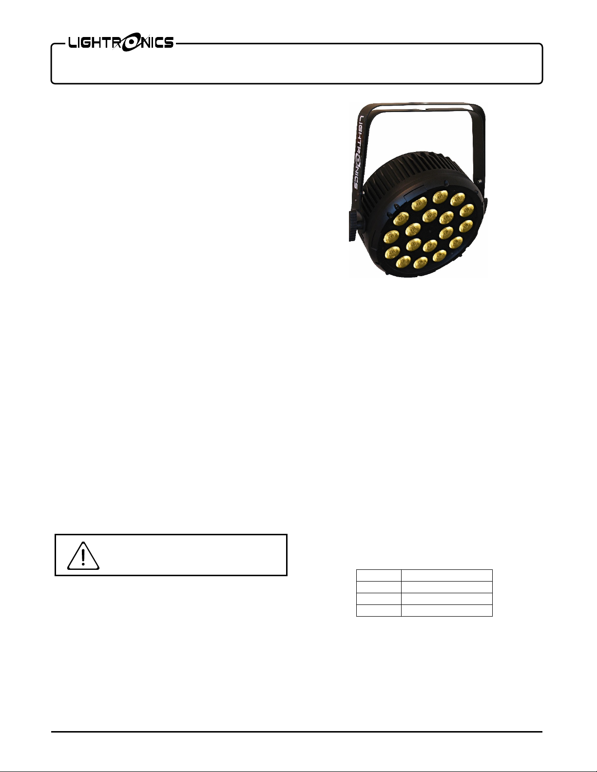
FXLD618FR2I LED FIXTURE
Version 1.1 OWNER’S MANUAL 05/11/2022
FEATURES AND SPECIFICATIONS
LEDS: 18, 6W each (Warm White, Cool White, 2in1)
Beam angle: 45° (25º opt io nal)
Control system: DMX-512 + Stand Alone Modes
DMX channels: 1/2/3/4/5
DMX connectors: 3 pin XLR
Voltage: 120-240 VAC 50/ 6 0Hz
Max power consumption: 120 Watts
Ingress Protection: IP20 - Indoor Use Only
Refresh Rate: > 3000Hz
Color Temp.: 3200K - 7000K
Cooling: Intelligent Fan
Body material: Die Cast Aluminum
Body color: Black (White optional)
Size: 9.9"L x 9.9"W x 4.5"D (without brackets)
Weight: 12.5 lbs. (4.5kg)
DESCRIPTION
The FXLD618FR2I is a variable white LED lighting
fixture. It is suitable for stage, house of worship,
entertainment venues, and other artistic applications.
It has several stand-alone control modes and can
operate via a DMX512 external signal.
A double yoke enables the fixture to be operated in
several positions.
INSTALLATION
LOCATION
Locate the unit indoors in a we ll ventilated area aw ay
from moisture and heat. Keep the vent holes clear.
Holes are provided on the y okes to install a lighting bar
pipe clamp. Use a safety cable when hanging the
fixture.
POWER CONNECTIONS
THE LINE CORD IS RATED FOR 7 AMPS M A XIM U M
THE SAFETY GRO UN D T ERMINAL O N THE PO WER
CABLE MUST BE USED.
DMX CONNECTIONS
A system using D MX contr ol sh ould be co nnect ed as a
chain of devices. In other words, the control signal
cable proceeds from the co ntroller to t he first rece iving
device and then to others in one continuous chain.
The fixture has a DM X IN and a DMX OUT conn ector
to be used to connect the chain. The control cable
should NOT be split into a multiple run star
arrangement with a cable running from the controller
directly to each receiving device.
DMX CONNECTOR PIN ASSIGNMENTS
The FXLD618FR2I rece ives a DMX sign al on the 3 pi n
MALE connector on one side of the unit. The 3 pin
FEMALE connector is use d to connect the next DMX
device on the control chain.
The FXLD618FR2I has a b lue turn and lock connector
for power input. A comp atible power cable is provide d
for connection to a 120 V AC, 15 Amp, 60Hz, ground ed
service. Push the blue co nnector on the c able straigh t
into the blue connector on the unit and twist approx.
1/8 turn clockwise to latch it.
The white turn and lock connector on the unit is used
to pass power on to another FXLD618FR2I unit. A
mating white connector is also provided.
www.lightronics.com
Lightronics Inc. 509 Central Drive, Virginia Beach, VA 23454 757 486 3588
DMX TERMINATION
A DMX chain shoul d be t erminated at the las t rec e iv ing
device on the chain. This is done by installing a
commonly available 1/ 4 Watt, 1 20 Ohm res istor acros s
the DATA - and DAT A + wi r es at t he las t dev ice. I f you
have only a few fixtures very close toget her and a v ery
short run to the controller, then you may be able to
operate without the terminator.
Page 2

CAUTION DO NOT OPEN UNIT
RISK OF ELECTRIC SHOCK
RISK OF FIRE
Page 2 of 4
FXLD618FR2I LED FIXTURE
Version 1.1 OWNER’S MANUAL 05/11/2022
OPERATION
A control panel on one side of the u nit is used to set
the operating options. It consists of an LED display
and four buttons (MENU, UP, DOWN, and ENTER).
.
Push MENU to ac ces s the oper at in g o pti ons. Then use
UP and DOWN to scroll thr ough the available choices.
When you reach t he op tio n y ou wan t to set or change push ENTER. Now you can view the current setting for
the option and/or chang e it. Push ENTER to save your
changes and activate the option. See the "MENU
NAVIGATION" diagram for additional details.
There are 7 operation modes: DMX, C olor Fade, Col or
Change, Color Select, Manual Level (2 selections),
Demo and Sound.
The display will def ault to 0XXC, which is a dis play of
the current LED plate temp erature. T he fan on th e unit
will only turn on w h en te mp er atur e is at or a bov e 45° C
and turns off at or below 34° C.
DMX OPERATION
Use the AXXX menu to se t the starting address of th e
unit. You can set the starting address of the unit with
the UP and DOWN buttons.
For DMX operation the FXLD618FR2I fixture can be
configured as a 1, 2, 3, 4, or 5 channel unit.
Set the CHXX me nu to 01 (1 channel), 02 (2 channel) ,
03 (3 channel), 04 (4 channel), or 05 (5 channel).
Detailed information on DMX channel operation is
given in the tables DMX VALUES AND FUNCTIONS.
The unit has an LED on the menu display (decimal
point). If the LED is flashing, the un it is NOT receiving
signal either from a DMX controller or from a master
fixture. LED will disappear once DM X is presen t.
MANUAL OPERATION
If there is no DMX signal provided to the unit, then
setting any of these w ill result in the unit that was s et
acting as a master. DMX overrides all manual settings.
www.lightronics.com
Lightronics Inc. 509 Central Drive, Virginia Beach, VA 23454 757 486 3588
COLOR FADE (CFXX)
The Color Fade mode cycles smoothly through 3
preset color temperature settings. Use the CFXX
menu to set the speed and activate the option. The
range is from 0 to 99 with 99 as the fastest.
COLOR CHANGE (CCXX)
The color change mode cycles through 3 preset color
temperature settings at a u ser defined speed. Use the
CCXX menu to set the rate of speed at which the
colors change. The range i s fr om 0 to 99 with 99 as the
fastest.
COLOR SELECT (CSXX)
For additional manual operations, you can use the
Color Select menu (CSXX) to select one of three
preset color temperature settings.
Warm White/Cool White MANUAL LEVEL
CONTROL
Individual color levels can be contr olled ma nually us in g
the u000 (warm white), and E000 (cool white) menus.
Use the UP and DOWN buttons to change the level,
then push ENTER when done. The range is 000 - 255.
DEMO MODE (dENo)
The Demo mode is a stand-alone mode designed to
test the unit. The Demo mode w ill not work if the unit
is receiving DMX. Exit Demo mode by entering
Channel mode menu option or insert a DMX signal.
SOUND MODE (Soun)
The unit reacts to sounds by cycling through three
preset color temper atures. There ar e no other setting s
within this mode.
Dimmer Delay (dEL0)
The operation of this function has been discontinued.
MAINTENANCE AND REPAIR
Page 3

CHANNEL
VALUE
FUNCTION
1
0-255
Warm & Cool White Intensity
CHANNEL
VALUE
FUNCTION
1
0 - 255
Warm White Intensity
2
0 - 255
Cool White Intensity
CHANNEL
VALUE
FUNCTION
1
0-255
Dimmer
2
0-255
Warm White Intensity
3
0-255
Cool White Intensity
CHANNEL
FUNCTION
VALUE
DESCRIPTION
4-127
Slow to Fast
Page 3 of 4
FXLD618FR2I LED FIXTURE
Version 1.1 OWNER’S MANUAL 05/11/2022
TROUBLESHOOTING
Check that you have power applied to the unit.
DMX VALUES AND FUNCTIONS
1 CHANNEL MODE
Check the DMX control cable.
Check the address settings of the unit and the
2 CHANNEL MODE
controller.
If no DMX signal is present, there will be a flashing
st
decimal point between 1
CLEANING
& 2nd character on display.
3 CHANNEL MODE
Do not use harsh chemica ls or solvents when cleaning
the fixture. A mild de tergent can be used sparingly if
needed. Use a cloth, do not spray or apply direct to
fixture. Ensure t hat the un it is complete ly dry before re use.
4 CHANNEL MODE
REPAIR
The fixture contains a 2 Amp 250VAC, fast acting,
5mm x 20mm extern ally accessible fuse. Replace the
fuse ONLY with the same size and type.
The FXLD618FR2I does not contain any other user
serviceable parts. Internal service on the unit by oth er
than Lightronics authorized agents will void the
warranty.
If service is required, contact the dealer from whom
you purchased the item, or contact the Lightronics
Service Department, 50 9 Central Drive, Virginia Beach,
VA 23454. Tel: 757 486 3588.
1
2
3 Warm White 0-255
4 Cool White 0-255
Master
Dimmer
Strobe
Control
0-255
0-3 No Strobe
128-131 No Strobe
132-255 Random
5 CHANNEL MODE
CHANNEL FUNCTION VALUE DESCRIPTION
0%-100%
Intensity
0%-100%
Intensity
0%-100%
Intensity
WARRANTY INFORMATION AND
REGISTRATION – CLICK LINK BELOW
www.lightronics.com/warranty.html
1
2
Master
Dimmer
Strobe
Control
0-255
0-3 No Strobe
4-127 Slow to fast
128-131 No Strobe
132-255 Random Strobe
0%-100%
Intensity
www.lightronics.com
Lightronics Inc. 509 Central Drive, Virginia Beach, VA 23454 757 486 3588
3 Warm White 0-255
4 Cool White 0-255
0-63 Off
5 Static Preset
64-127 Warm White
128-191 Cool White
192-255 Neutral White
0%-100%
Intensity
0%-100%
Intensity
Page 4

Page 4 of 4
FXLD618FR2I LED FIXTURE
Version 1.1 OWNER’S MANUAL 05/11/2022
MENU NAVIGATION
www.lightronics.com
Lightronics Inc. 509 Central Drive, Virginia Beach, VA 23454 757 486 3588
 Loading...