

Page 1 of 6
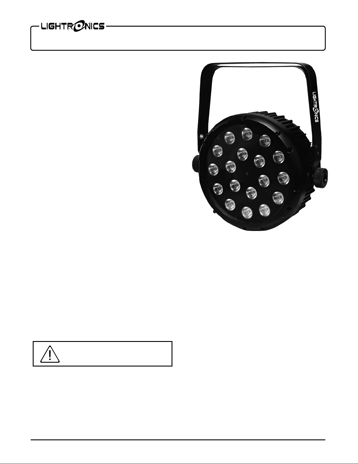
FXLD1018FRP5I LED FIXTURE
Version 0.1 OWNERS MANUAL 07/08/2013
FEATURES AND SPECIFICATIONS
LEDS: 18, 10W each (RGBWA, 5 in 1)
White LED Color Temperature: 6500K
Beam angle: 25 º
Control system: DMX-512 + Stand Alone Modes
DMX channels: 5/9
DMX connectors: 3 pin XLR and 5 pin XLR
Refresh Rate: >400 Hz)
Voltage: 120 - 240 VAC 50/60Hz
Max power consumption: 200 Watts
Cooling: Internal Fan
Body material: Die Cast Aluminum
Body color: Black
Size: 13.3"L x 11.81"W x 4.56"H (without brackets)
Weight: 16.5 lbs (7.5 kg)
DESCRIPTION
The FXLD1018FRP5I is a RGBWA LED lighting
fixture. It is suitable for stage, disco, night club, and
other artistic applications. It has several stand alone
control modes and can operate via a DMX-512
external signal.
A double yoke enables the fixture to be operated in
several positions.
INSTALLATION
LOCATION
The FXLD1018FRP5I is rated IP20 and is intended for
INDOOR USE ONLY.
Locate the unit in a well ventilated area away from
moisture and heat. Keep the vent holes clear. Holes
are provided on the yokes to install a lighting bar pipe
clamp. Use a safety cable when hanging the fixture.
POWER CONNECTIONS
RISK OF ELECTRIC SHOCK
CAUTION
The FXLD1018FRP5I has a blue powercon style
connector for power input. A compatible power cable
is provided for connection to a 120 VAC, 15 Amp,
60Hz, grounded service. Push the blue connector on
the cable straight into the blue connector on the unit
and twist aprox. 1/8 turn clockwise to latch it.
The white powercon style connector on the unit is used
to pass power on to another FXLD1018FRP5I unit. A
mating white connector is also provided.
Caution is advised since the line cord is rated for
aprox. 7 Amps maximum.
THE SAFETY GROUND TERMINAL ON THE POWER
CABLE MUST BE USED.
DMX CONNECTIONS
A system using DMX control should be connected as a
chain of devices. In other words the control signal
cable should proceed from the controller to the first
receiving device and then to others in a continuous
"daisy chain" fashion.
The fixture has a DMX IN and a DMX OUT connector
to be used to connect the chain. The control cable
should NOT be split into a multiple run star
arrangement with a cable running from the controller
directly to each receiving device pack.
www.lightronics.com
Lightronics Inc. 509 Central Drive Virginia Beach, Va 234354 757 486 3588
Page 2 of 6
FXLD1018FRP5I LED FIXTURE
Version 0.1 OWNERS MANUAL 07/08/2013
DMX CONNECTOR PIN ASSIGNMENTS
There are two different connectors generally used for
DMX control. They are both XLR type connectors.
Some units use 3 pin connectors. Others use 5 pin. The
FXLD1018FRP5I has both. DMX can be received on
either the 3 pin or 5 pin MALE male connector on the
back of the unit. The 3 and 5 pin FEMALE connectors
are used to connect to the next DMX device on the
control chain.
The table below shows the pin assignments for BOTH
the 3 pin and 5 pin connectors.
DMX TERMINATION
PIN # SIGNAL NAME
1 DMX COMMON
2 DMX DATA 3 DMX DATA +
4 NOT USED
5 NOT USED
A DMX chain should be terminated at the last
receiving device on the chain. This is done by
installing a commonly available 1/4 Watt, 120 Ohm
resistor across the DATA - and DATA + wires at the
last device. If you have only a few fixtures very close
together and a very short run to the controller then you
may be able to operate without the terminator.
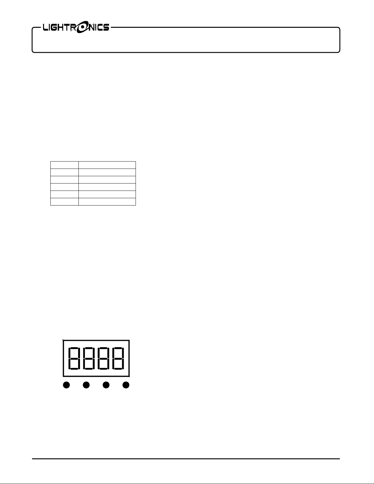
OPERATION
A control panel on the back of the unit is used to set
the operating options. It consists of an LED display
and four buttons
(MENU, UP, DOWN, and ENTER)
CONTROL PANEL
Push
MENU UP DOWN ENTER
MENU
to access the operating options. When
you reach the option you want to set or change - use
UP or DOWN to set a value. Push
ENTER
to save your
changes and activate the option. See the "MENU
NAVIGATION" diagram for additional details.
There are 6 operation modes: DMX, Color Fade, Color
Change, Color Select, Demo, and Slave.
DMX OPERATION
For DMX operation the FXLD1018FRP5I fixture can
be configured as a 5 channel , or 9 channel unit.
Use the dxxx (5 ch) or d.xxx (9 ch) menu to set the
starting address of the unit. You can select the starting
address of the unit with the UP and DOWN buttons.
Detailed information on DMX channel operation is
given in the tables
MANUAL OPERATION (
DMX VALUES AND FUNCTIONS
CS01
)
.
For manual operation you can use the Color Select
menu (CS01) to select a color and level.
COLOR FADE
(CF01)
The Color Fade mode cycles smoothly through a
sequence of colors. Use the CS01 menu to set the
speed and activate the option. The range is from 1 to
99. 99 is fastest.
COLOR CHANGE (
CC01
)
The COLOR CHANGE mode switches continuously
through a sequence of colors. Use the CC01 menu to
set the speed. The range is from 1 to 99. 99 is fastest.
DEMO MODE (
dENo
)
The unit cycles through a fixed series of colore and
fades. There are no other adjustments or settings in
this mode.
MASTER/SLAVE OPERATION
The FXLD1018FRP5I can operate in a Master/Slave
mode where one of the units can synchronize other
units of the same model.
Connect the units together using the DMX IN and
DMX OUT connectors. Set the unit to be the Master
in one of the modes above. Use the SLAV menu to set
a unit as a slave.
www.lightronics.com
Lightronics Inc. 509 Central Drive Virginia Beach, Va 234354 757 486 3588

Page 3 of 6
FXLD1018FRP5I LED FIXTURE
Version 0.1 OWNERS MANUAL 07/08/2013
MAINTENANCE AND REPAIR
TROUBLESHOOTING
CAUTION DO NOT OPEN UNIT
RISK OF ELECTRIC SHOCK
RISK OF FIRE
Check that you have power applied to the unit.
Check the DMX control cable.
Check the address settings of the unit and the
controller.
CLEANING
Do not use harsh chemicals or solvents when cleaning
the fixture. A mild detergent can be used sparingly if
needed. Ensure that the unit is completely dry before
re-use.
REPAIR
The fixture contains a 2 Amp, fast acting, 5mm x
20mm externally accessible fuse. Replace the fuse
ONLY with the same size and type.
The FXLD1018FRP5I does not contain any other user
serviceable parts. Internal service on the unit by other
than Lightronics authorized agents will void the
warranty.
If service is required, contact the dealer from whom
you purchased the item, or contact the Lightronics,
Service Department, 509 Central Drive, Virginia
Beach, VA 23454. Tel: 757 486 3588.
www.lightronics.com
Lightronics Inc. 509 Central Drive Virginia Beach, Va 234354 757 486 3588

Page 4 of 6
FXLD1018FRP5I LED FIXTURE
Version 0.1 OWNERS MANUAL 07/08/2013
MENU NAVIGATION
www.lightronics.com
Lightronics Inc. 509 Central Drive Virginia Beach, Va 234354 757 486 3588
Page 5 of 6
FXLD1018FRP5I LED FIXTURE
Version 0.1 OWNERS MANUAL 07/08/2013
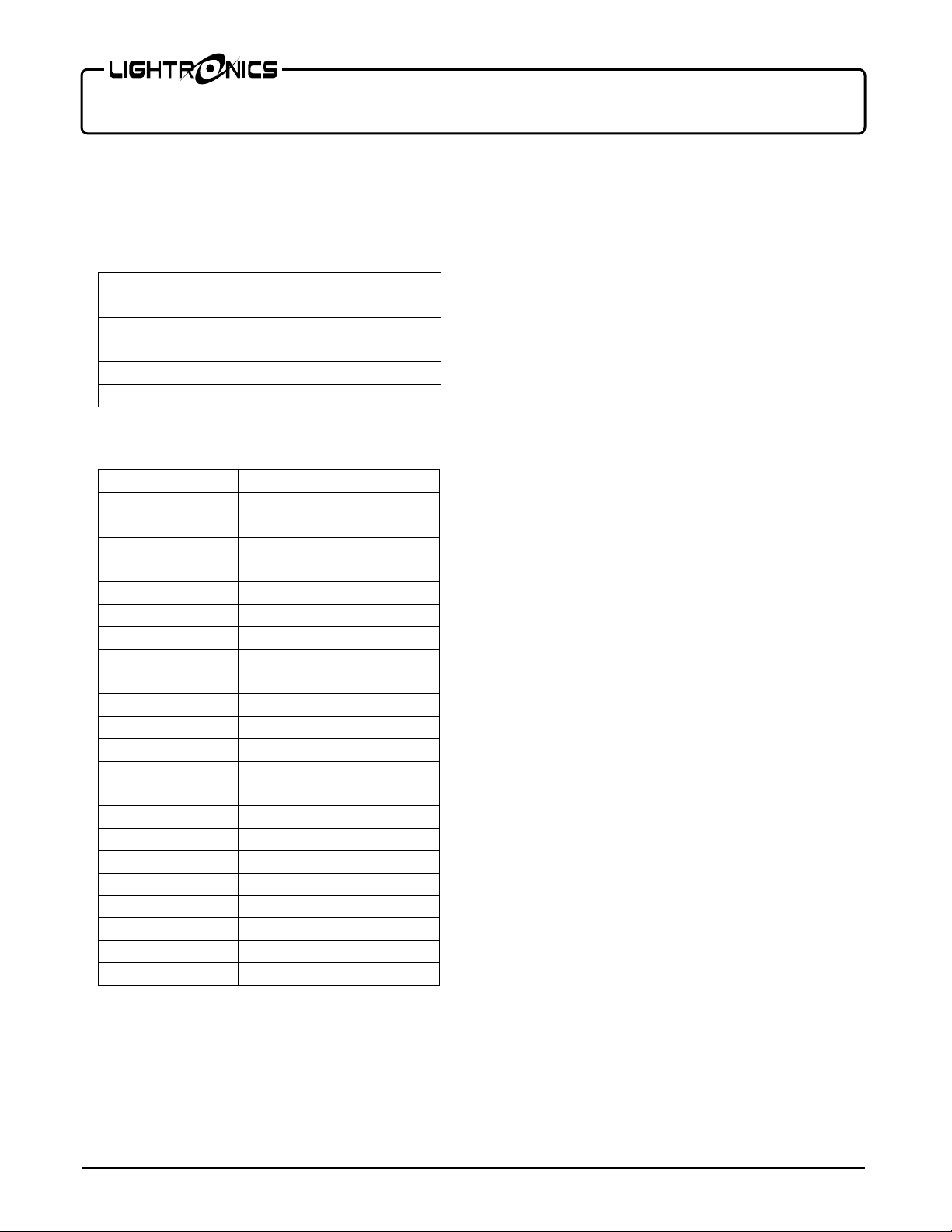
DMX VALUES AND FUNCTIONS
5 CHANNEL MODE (MODE dXXX)
CHANNEL NO. FUNCTION
1 0 - 255 Red Level
2 0 - 255 Green Level
3 0 - 255 Blue Level
4 0 - 255 White Level
5 0 - 255 Amber Level
9 CHANNEL MODE (MODE d.XXX)
CHANNEL NO. FUNCTION
1 0 - 255 Red Level
2 0 - 255 Green Level
3 0 - 255 Blue Level
4 0 - 255 White Level
5 0 - 255 Amber Level
6 Master Dimmer
7 0 - 1 No Strobe
2 - 255 Strobe Speed
8 0 - 32 Red
33 - 65 Red/Green
66 - 96 Red/Green
97 - 129 Green/Blue
130 - 160 Green/Blue
161 - 191 Red/Blue
192 - 224 Red/Blue
225 - 254 R/G/B/A/W
255 All on
9 0 - 9 No Function
10 - 63 R + B Auto
64 - 127 R + G Auto
128 - 191 G + B Auto
192 - 255 R+G+B+w+A Auto
www.lightronics.com
Lightronics Inc. 509 Central Drive Virginia Beach, Va 234354 757 486 3588

Y
This product is warranted for a period of TWO YEARS from the date of purchase against
defects in materials and workmanship.
This warranty is subject to the following restrictions and conditions:
A) If service is required, you may be asked to provide proof of purchase from an
authorized Lightronics dealer.
B) This warranty is valid only for the original purchaser of the unit.
C) This warranty does not apply to damage resulting from abuse, misuse, accidents,
shipping, and repairs or modifications by anyone other than an authorized
Lightronics service representative.
D) This warranty is void if the serial number is removed, altered or defaced.
E) This warranty does not cover loss or damage, direct or indirect arising from the use or
inability to use this product.
F) Lightronics reserves the right to make any changes, modifications, or updates as
deemed appropriate by Lightronics to products returned for service. Such changes
may be made without prior notification to the user and without incurring any
responsibility or liability for modifications or changes to equipment previously
supplied. Lightronics is not responsible for supplying new equipment in accordance
with any earlier specifications.
G) This warranty is the only warranty either expressed, implied, or statutory, upon which
the equipment is purchased. No representatives, dealers or any of their agents are
authorized to make any warranties, guarantees, or representations other than
expressly stated herein.
H) This warranty does not cover the cost of shipping products to or from Lightronics for
service.
I) Lightronics Inc. reserves the right to make changes as deemed necessary to this
warranty without prior notification.
WARRANT
Lightronics Inc. 509 Central Drive Virginia Beach, VA 23454 20100211
 Loading...