

Page 1
PROFILE SPOT575 OWNERS MANUAL Page 1 of 4
Y
Ellipsoidal Lighting Fixture Version 20101007
INTRODUCTION
Thank you for purchasing the Profile Spot 575 lighting
fixture. This manual contains important information
about safe installation and use of this fixture. Please read
and follow these instructions carefully and keep this
manual for future reference.
The Profile Spot 575 is suitable for stage, disco, night club,
and other artistic applications.
The housing is a high quality aluminum alloy with an
insulating paint finish.
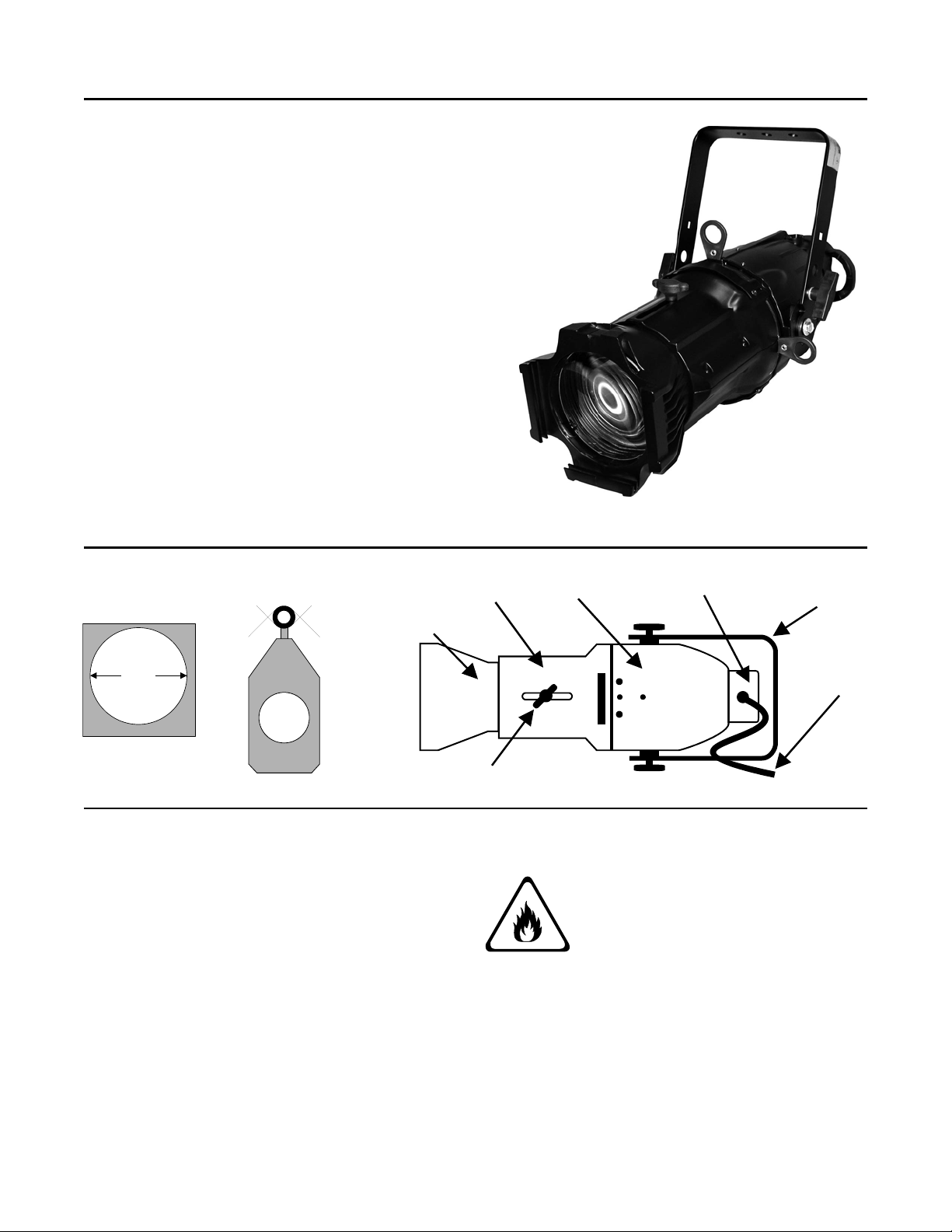
The
Profile Spot 575 includes a gel filter holder. A size
"B" gobo holder is also provided.
The product complies with CE norms and standards and is
certified to UL 1573 by MET Laboratories.
GEL HOLDER
"B" GOBO HOLDER
BARREL
LENS TUBE
REFLECTOR
HOUSING
LAMP HOUSING
OKE
5.375"
POWER
CABLE
FOCUS KNOB
MODELS
The Profile Spot 575 is provided as one of five beam
width models (10º, 19º, 26º, 36º, and 50º).
Each model is available in either black or white color.
Lens tubes are interchangeable between models and are
marked with the beam width.
The 10º model has a larger lens tube which is
packaged separately from the main housing.
INSTALLATION
CAUTION RISK OF FIRE
The fixture must be located a minimum
of 1.5 meters from flammable objects.
The fixture is for
INDOOR USE ONLY. Use only in dry
locations. Keep this device away from moisture,
excessive heat, humidity, and dust.
The fixture must be installed in a location with
adequate ventilation, at least 1.5 meters from adjacent
surfaces. Do not allow vent holes to be blocked.
Use a safety cable when installing this fixture. They
are inexpensive and easy to use.
Page 2
PROFILE SPOT575 OWNERS MANUAL Page 2 of 4
Ellipsoidal Lighting Fixture Version 20101007
POWER CONNECTIONS
DANGER
RISK OF ELECTRIC SHOCK
The fixture must be correctly grounded
and must be installed to comply with
all applicable regulations.
The unit is supplied with a power cable and may be
provided with a power cable connector. The two wires
with WHITE SLEEVING are for the HOT (Power) and
the NEUTRAL.
The GREEN / YELLOW conductor in the power cable
is connected to the fixture case as a safety ground.
This conductor must be used if installing a alternate
cable connector.
LAMP REMOVAL / INSTALLATION
The Profile Spot 575 fixture uses a OSRAM GLA/575
or GLE/750 (G9.5 Base) lamp
Before installing a lamp verify that the lamp is
compatible with the voltage at your facility. Operating
lamps beyond their rated voltage reduces lamp life and
can cause other lamp failures.
Disconnect all power from the fixture.
Allow the fixture to cool off before proceeding.
Do not touch the lamp glass envelope with your
fingers
1. Unscrew the knurled screw on the lamp housing.
2. Remove the lamp housing from the fixture.
3. If replacing a lamp, remove the old lamp from the
socket.
4. Insert a lamp into the lamp socket.
5. Reinstall the lamp housing.
Do not operate the lamp unless the lamp housing
is installed in the fixture.
LAMP ADJUSTMENT
The lamp holder is aligned at the factory. Due to
differences between lamps, fine adjustment may
improve light performance.
Operate the fixture at full intensity. Open the shutters.
Focus the light on a flat surface such as a wall.
Center the hot-spot (the brightest part of the beam)
using the 3 adjustment screws A, B, C. Turn one
screw at a time to drag the hot-spot diagonally across
the projected image.
If you cannot detect a hot-spot, pull the lamp in by
turning all screws A, B, and C clockwise ¼ turn, one at
a time, until the light is evenly distributed.
If the light is brighter at the edges, or if light output is
low, the lamp is too far back in the reflector. Push the
lamp out by turning the screws A, B, and C ¼ turn
counterclockwise, one at a time, until the light is bright
and evenly distributed.
FOCUSING
1. Loosen the focus knob on the barrel.
2. Adjust the focus by sliding the lens tube forward
or backward.
3. Tighten the focus knob.
OPERATION
CAUTION - HOT SURFACES
Do not touch any part if the fixture
during operation. It can operate at
temperatures which can cause severe
burns.
Do not operate the lamp unless the lamp holder is
installed in the fixture.
The lens and gel holder must be installed when the
fixture is operating.
Do not project the beam onto nearby flammable
surfaces. The minimum distance is 5 meters.
Once correctly installed, the fixture may be operated
by applying power via a dimmer or other compatible
power.
Switching the lamp on and off at short intervals will
reduce the life of both the lamp and the fixture.
CLEANING AND MAINTENANCE
DANGER
RISK OF ELECTRIC SHOCK
Disconnect all power from the fixture
Before proceeding.
Allow the fixture to cool off before proceeding.
Page 3

PROFILE SPOT575 OWNERS MANUAL Page 3 of 4
Ellipsoidal Lighting Fixture Version 20101007
To ensure the reliability of the fixture it should be
regularly cleaned and inspected.
The vent slots should be cleaned monthly. The fixture
interior should be cleaned annually using a vacuum
cleaner or air jet. The objective lens may require
weekly cleaning depending on the operating
environment.
Please use a moist, lint free cloth. NEVER USE
ALCOHOL OR SOLVENTS!
The power cables and connectors should be inspected
monthly for damages, and material fatigue.
There are no serviceable parts inside the device except
for the lamp. Please refer to the instructions under
"Lamp Removal / Installation". Service by other than
Lightronics authorized agents may void your warranty.
The best way to prolong the life of your unit is to keep
it cool, clean, and dry.
BEAM SIZE
10 DEGREE
Distance (ft) 80 90 100 110 120
TECHNICAL SPECIFICATIONS
Power Supply: 120VAC, 60 Hz
Lamp: OSRAM GLA/575 or GLE/750 (G9.5 Base) lamp
Power Consumption: 600W/750W
Dimensions (L x W x H): 650 x 180 x 260mm
Weight: 6kg
Maximum Ambient Temp.: 45 deg. C
Maximum Housing Temp.: (steady state): 245 deg. C
UL 1573 compliant. Listed By MET Laboratories.
Beam Diam. 12.8 14.4 16 17.6 19.2
19 DEGREE
Distance (ft) 40 50 60 70 80
Beam Diam. 10.8 13.5 16.2 18.9 21.6
26 DEGREE
Distance (ft) 30 40 50 60 70
Beam Diam. 9.9 13.2 16.5 19.8 23.1
36 DEGREE
Distance (ft) 10 20 30 40 50
Beam Diam. 4.5 9.0 13.5 18.0 22.5
50 DEGREE
Distance (ft) 10 20 30 40 50
Beam Diam. 5.7 11.4 13.5 22.8 28.5
Page 4

W
Y
This product is warranted for a period of TWO YEARS from the date of purchase against defects in
materials and workmanship.
This warranty is subject to the following restrictions and conditions:
A) If service is required, you may be asked to provide proof of purchase from an authorized
Lightronics dealer.
B) This warranty is valid only for the original purchaser of the unit.
C) This warranty does not apply to damage resulting from abuse, misuse, accidents, shipping,
and repairs or modifications by anyone other than an authorized Lightronics service
representative.
D) This warranty is void if the serial number is removed, altered or defaced.
E) This warranty does not cover loss or damage, direct or indirect arising from the use or
inability to use this product.
F) Lightronics reserves the right to make any changes, modifications, or updates as deemed
appropriate by Lightronics to products returned for service. Such changes may be made
without prior notification to the user and without incurring any responsibility or liability for
modifications or changes to equipment previously supplied. Lightronics is not responsible
for supplying new equipment in accordance with any earlier specifications.
G) This warranty is the only warranty either expressed, implied, or statutory, upon which the
equipment is purchased. No representatives, dealers or any of their agents are authorized
to make any warranties, guarantees, or representations other than expressly stated herein.
H) This warranty does not cover the cost of shipping products to or from Lightronics for
service.
I) Lightronics Inc. reserves the right to make changes as deemed necessary to this warranty
without prior notification.
ARRANT
Lightronics Inc. 509 Central Drive Virginia Beach, VA 23454 20100211
 Loading...