

Page 1
Page 1 of 5
W
A
p
FL-4020 FLUORESCENT BALLAST CONTROLLER
Version 1.0 OWNERS MANUAL 10/06/2005
PRODUCT DESCRIPTION
The FL-4020 is a four channel controller add on product for the AR-1202 Architectural dimmer. It provides control
of dimmable fluorescent lighting ballasts. The FL-4020 provides four 2400 Watt channels of fluorescent dimming
which is interfaced to the AR-1202 control circuitry. The AR-1202 uses its four auxillary channels (13 – 16 ) to
control the FL-4020. Dual SCR “zero crossing” switching is used to control the switched hot lines.
The FL-4020 is supplied in two versions:
FL-4020A: Controls ballasts which use a switched 120 VAC “hot” and a dimmed 120 VAC as a control signal.
FL-4020D: Controls ballasts which use a switched 120 VAC “hot” and a 0-10 VDC dimming control signal.
INSTALLATION
MAKE CERTAIN POWER IS REMOVED FROM THE FEED CIRCUITS
BEFORE YOU BEGIN INSTALLATION.
The unit should be wall mounted close to an AR-1202 dimmer. The unit may be "stood off" from the wall (aprox.
1") to assure clear airflow across the rear heat sink surface. A 120VAC 20 Amp power input must be provided for
each dimming channel. Each channel may control multiple ballasts as long as the channel load does not exceed
2400 Watts. The internal low current electronic circuitry is powered, via a 1/2 Amp 250VAC fast blow fuse, by the
H1 input power connection.
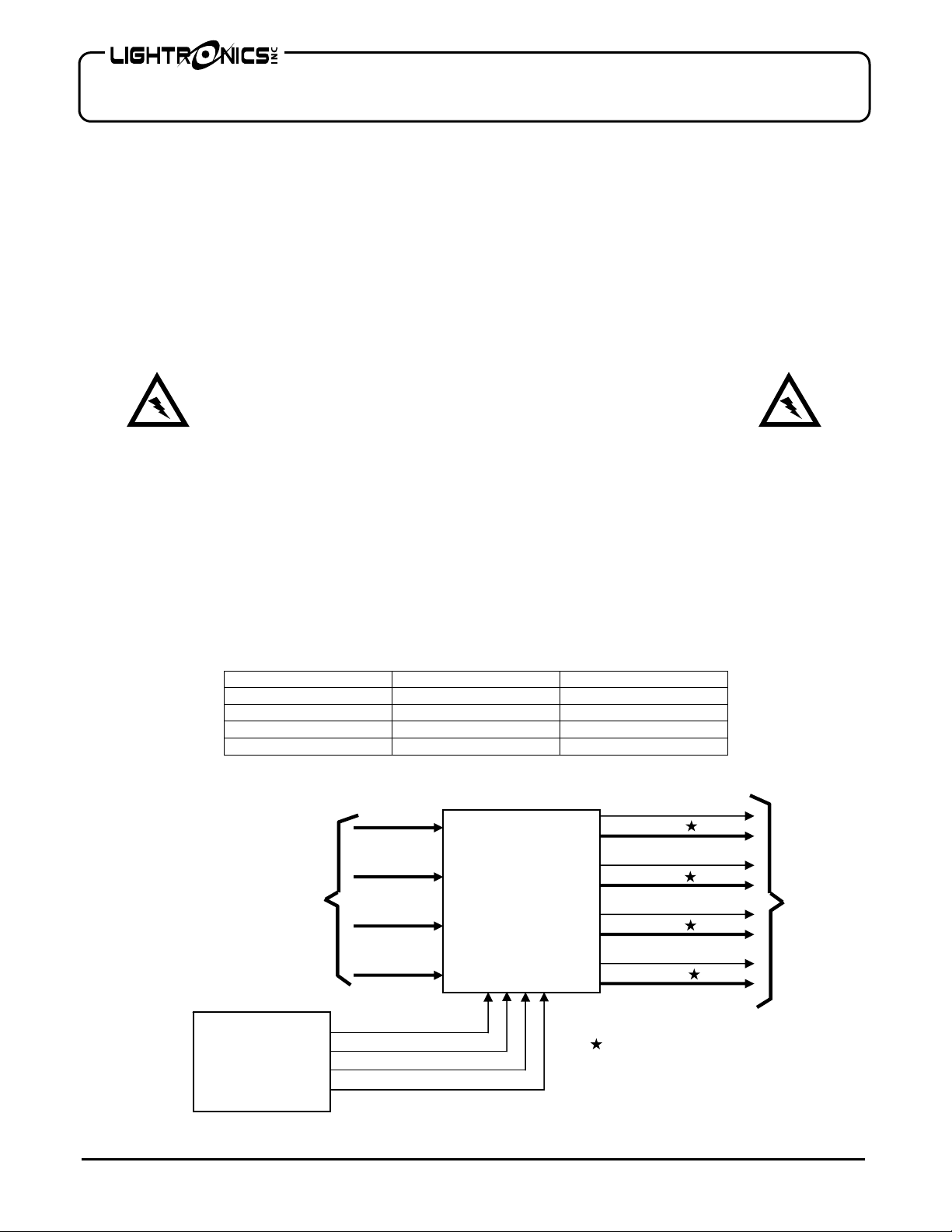
REQUIREMENTS FOR THREE PHASE OPERATION:
In order to provide zero crossing switching, the AR-1202 uses a specific phase sequen ce when operated with 3
phase power. The sequence convention must also be adhered to when connecting the FL-4020. The phase
connected to the AR-1202 H1 power input terminal must also be used for channels 1 and 4 of the FL-4020. The
AR-1202 H2 phase must be used for FL-4020 channel 2. The AR-1202 H3 phase must be used for FL-4020
channel 3. The table below summarizes this requirement.
POWER PHASE
H1 13 13
H2 14 14
H3 15 15
H1 16 16
TYPICAL CONNECTION SCHEME
User supplied
120VAC feeds from
circuit breaker
anel
AR-1202
Channel 16 Control
Channel 15 Control
Channel 14 Control
Channel 13 Control
www.lightronics.com
Lightronics Inc 509 Central Drive Virginia Beach, VA 23454 Tel 757 486 3588
ARNING
R-1202 CHANNEL FL-4020 CHANNEL
SWITCHED 120VAC
CH 16
CH 15
FL-4020
CH 14
CH 13
Control Signal
SWITCHED 120VAC
Control Signal
SWITCHED 120VAC
Control Signal
SWITCHED 120VAC
Control Signal
Control Signal may be either 0 - 10 VDC
120VAC Dimmed hot
To
Lamp
Ballasts
OR
Page 2
Page 2 of 5
FL-4020 FLUORESCENT BALLAST CONTROLLER
Version 1.0 OWNERS MANUAL 10/06/2005
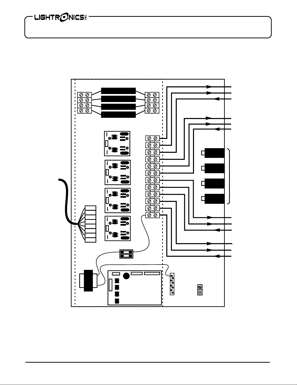
FL-4020A CONNECTIONS
16
CONTROL
INPUTS
FROM
AR-1202
15
14
1616+
1515+
1414+
1313+
1/2 Amp Fuse
13
TRANSFORMER
CIRCUIT
BOARD
NEUTRALS
GROUND
16 SWITCHED
16 DIMMED
16 HOT
15 SWITCHED
15 DIMMED
15 HOT
CIRCUIT
BREAKERS
14 SWITCHED
14 DIMMED
14 HOT
13 SWITCHED
13 DIMMED
13 HOT
www.lightronics.com
Lightronics Inc 509 Central Drive Virginia Beach, VA 23454 Tel 757 486 3588
Page 3
Page 3 of 5
T
T
FL-4020 FLUORESCENT BALLAST CONTROLLER
Version 1.0 OWNERS MANUAL 10/06/2005
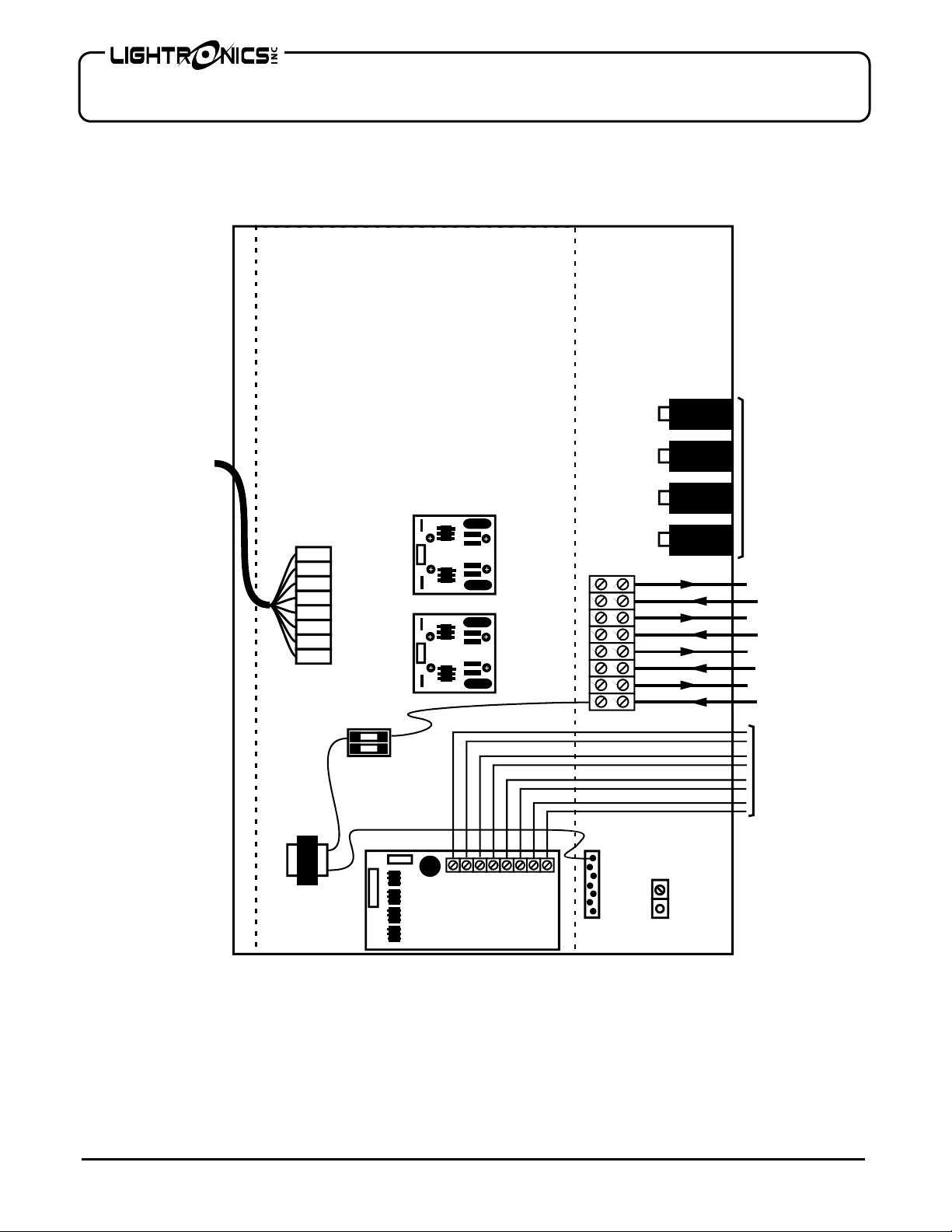
FL-4020D CONNECTIONS
CONTROL
INPUTS
FROM
AR-1202
1616+
1515+
1414+
1313+
1/2 Amp
FUSE
TRANSFORMER
13+
CIRCUIT
BOARD
13 -
14+
14 -
15+
15 -
16+
16 -
NEUTRALS
16
15
CIRCUIT
BREAKERS
14
13
16 BALLAS
16 HOT IN
15 BALLAST
15 HOT IN
14 BALLAS
14 HOT IN
13 BALLAST
13 HOT IN
0 - 10 VDC
CONTROL
TO
BALLASTS
GROUND
www.lightronics.com
Lightronics Inc 509 Central Drive Virginia Beach, VA 23454 Tel 757 486 3588
Page 4
Page 4 of 5
FL-4020 FLUORESCENT BALLAST CONTROLLER
Version 1.0 OWNERS MANUAL 10/06/2005
INSTALLATION NOTES
1. Chassis is 18”H x 15”W x 4.25” D. Mulitple knockouts are provided at top and bottom for wiring access.
2. The unit weighs aprox. 10 pounds.
3. Mounting holes are provided at rear of box. Box should be spaced aprox. 1” from wall.
4. A 12 ft wiring harness (with connector) is provided to connect to an AR-1202 dimmer.
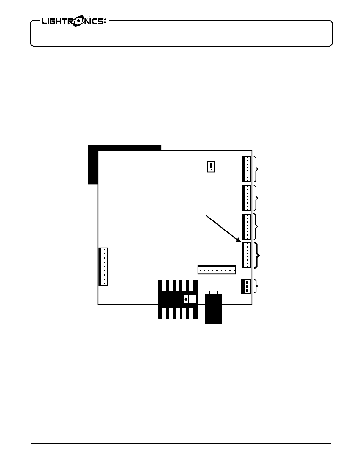
FL-4020 CONTROL SIGNAL CONNECTIONS AT AR-1202
The 8 conductor cable which supplies the control inputs to the FL-4020 is supplied with a connector at the AR1202 end. This cable connects directly to J7 on the circuit board located on the AR-1202 door. The location of
J7 is shown in the diagram below.
AR-1202
CIRCUIT BOARD
ASSY
(REAR VIEW SHOWN)
OWNER MAINTENANCE
There is a 1/2 Amp., 250 Volt, fast acting fuse in the unit to protect the internal electronic circuits from an
overvoltage condition. The fuse may be replaced ONLY by a fuse of the same size and type.
The best way to prolong the life of your unit is to keep is cool, clean, and dry. It is important that the cooling
intake and exit vent holes are clean and unobstructed.
Service by other than Lightronics authorized agents may void your warranty.
OPERATING AND MAINTENANCE ASSISTANCE
If service is required, contact the dealer from whom you purchased the equipment or contact Lightronics, Service
Department, 509 Central Drive, Virginia Beach, VA 23454 TEL 757 486 3588
J7
3 PH
1 PH
POWER
INPUT
CHAN
1 - 4
CHAN
5 - 8
CHAN
9 - 12
1
2
3
4
5
6
7
8
CHAN
13 - 16
TO
FL-4020
12 VAC
www.lightronics.com
Lightronics Inc 509 Central Drive Virginia Beach, VA 23454 Tel 757 486 3588
Page 5

All Lightronics products are warranted for a period of TWO/FIVE YEARS from the date of
purchase against defects in materials and workmanship.
WARRANTY
This warranty is subject to the following restrictions and conditions:
A) If service is required, you may be asked to provide proof of purchase from an authorized
Lightronics dealer.
B) The FIVE YEAR WARRANTY is only valid if the warranty card is returned to Lightronics
accompanied with a copy of the original receipt of purchase within 30 DAYS of the
purchase date, if not then the TWO YEAR WARRANTY applies. Warranty is valid only for
the original purchaser of the unit.
C) This warranty does not apply to damage resulting from abuse, misuse, accidents, shipping,
and repairs or modifications by anyone other than an authorized Lightronics service
representative.
D) This warranty is void if the serial number is removed, altered or defaced.
E) This warranty does not cover loss or damage, direct or indirect arising from the use or
inability to use this product.
F) Lightronics reserves the right to make any changes, modifications, or updates as deemed
appropriate by Lightronics to products returned for service. Such changes may be made
without prior notification to the user and without incurring any responsibility or liability for
modifications or changes to equipment previously supplied. Lightronics is not responsible
for supplying new equipment in accordance with any earlier specifications.
G) This warranty is the only warranty either expressed, implied, or statutory, upon which the
equipment is purchased. No representatives, dealers or any of their agents are authorized
to make any warranties, guarantees, or representations other than expressly stated herein.
H) This warranty does not cover the cost of shipping products to or from Lightronics for
service.
I) Lightronics Inc. reserves the right to make changes as deemed necessary to this warranty
without prior notification.
Page 6

Lightronics Inc. 509 Central Drive Virginia Beach, VA 23454 20050125
 Loading...