

Page 1
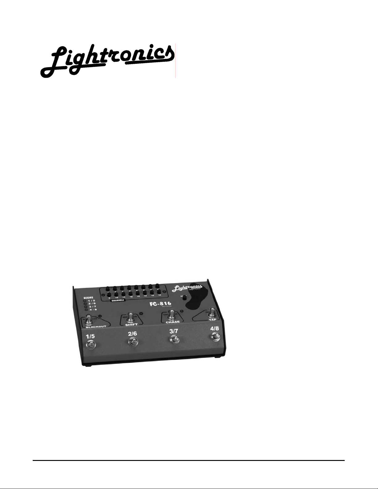
CONTROL CONSOLE
FC-816
FOOT OPERATED
Revision 1.1
02/20/2005
www.lightronics.com
Lightronics Inc. 509 Central Drive Virginia Beach, VA 23454 Tel 757 486 3588
Page 2

Page 2 of 7
FC - 816 CONTROL CONSOLE
Version 1.1 OWNERS MANUAL 02/20/2005
IMPORTANT: Please take time to read this manual before
operating your FC-816 Control Console
UNIT DESCRIPTION AND FUNCTIONS
The FC-816 is a 16 channel, 9 scene, multiplex output dimmer controller. It is intended as a foot operated
controller. Eight scenes can be user recorded and scene fade time can be user set. A ninth scene is available as
a manual mode scene. A blackout function is provided.
The unit can produce four user recorded chase sequences of up to fourteen steps each. Chase advance timing
can be controlled by the operator or by an external audio signal. Chase steps may consist of user set sequences,
entire scenes, or a combination of both.
The FC-816 is powered by the dimmer to which it is connected and will operate in both the LIGHTRONICS and
NSI/SUNN modes. See installation instructions below for dimmer mode limitations.
The FC-816 will operate with MIDI equipment which can be used to control scenes and chases.
INSTALLATION
The FC-816 should be kept away from moisture and direct sources of heat.
Connect the FC-816 controller to a Lightronics (or compatible) dimmer using a multiplex control ca ble with 3 pin
XLR connectors. Connect the cable to the MPX OUT, 3 pin, female, XLR connector on the back edge of th e unit.
The FC-816 will NOT operate unless connected to a powered and operating dimmer.
Dimmers connected to the FC-816 must
An audio signal to control chase rates can be connected to the AUDIO INPUT connector on the back e dge of the
unit. This is a 1/4 inch audio jack.
The MIDI INPUT and MIDI OUTPUT connectors on the back edge of the unit are 5 pin, female, DIN connectors
and are to be used only with MIDI compatible equipment.
SETUP AND OPERATION
Before setting up FC-816 scenes and chases you should reset it to ensure you are starting from a known set of
conditions. Resetting the unit will clear all scenes, set a factory programmed fade rate of 3 seconds, and set
factory programmed test chase patterns.
To reset the unit:
1. Disconnect the MPX cable to remove unit power.
2. Hold down SHIFT and CHASE.
3. Reconnect the MPX cable with SHIFT and CHASE still down. Hold until the BLACKOUT indicator lights.
You should check channel address settings at your dimmers before proceeding with FC-816 setup.
www.lightronics.com
Lightronics Inc. 509 Central Drive Virginia Beach, VA 23454 Tel 757 486 3588
ALL be in either the LIGHTRONICS or the NSI/SUNN modes.
Page 3
Page 3 of 7
FC - 816 CONTROL CONSOLE
Version 1.1 OWNERS MANUAL 02/20/2005
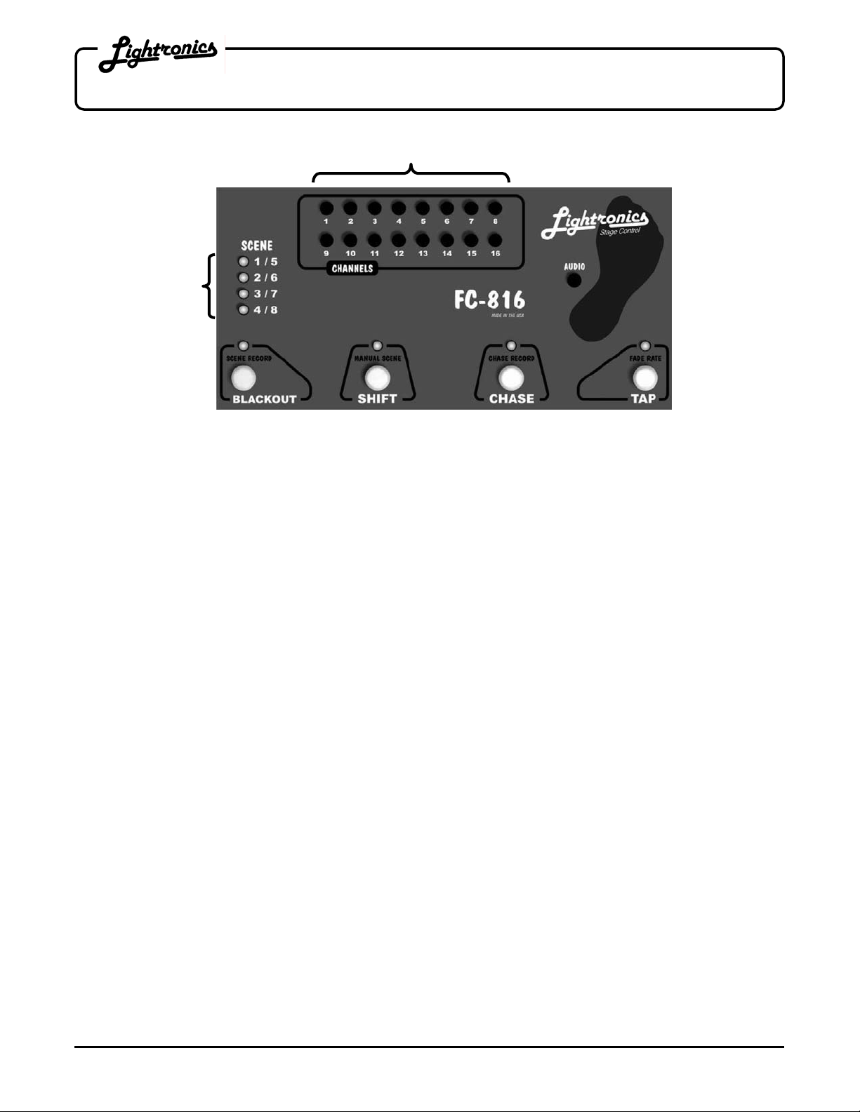
SCENE
SELECT
INDICATORS
GENERAL OPERATION
The FC-816 is intended to operate using preset scenes which are created and recorded by the operator before a
performance. Scenes are created using the rotating channel intensity faders and recorded by a holding down the
BLACKOUT and SHIFT foot switches at the same time. Playback of scenes is done using the scene foot
switches. The scene indicator LED's on the left part of the unit indicate which scene is active.
Chase functions operate by creating and recording a sequence of chase steps before a performance. Playback of
chases is done using foot switches. The chase LED indicates which chase is active. Scenes and chase s may
be active at the same time. Only one scene and one chase may be active at any given time.
SCENE FUNCTIONS
SELECTING SCENES
The scene select buttons are located on the front (angled) section of the unit and labeled as: 1/5 2/6 3/7 4/8.
To select one of scenes 1 through 4 - Push any scene button. The associated scene LED will come on. To
select one of scenes 5 through 8 - Push SHIFT, then press a scene button. The associated scene LED will flash.
If you release the scene button quickly - the unit will switch to the selected scene instantly. If you hold the button
down for more than 1 second - the unit will fade to the selected scene at the preset rate.
Press BLACKOUT once to turn off the active scene. Holding BLACKOUT for more than 1 second will cause the
selected scene to blackout at the preset fade rate.
TO SET THE SCENE FADE RATE: Hold down TAP until the TAP indicator lights (about 4 secs.). Fade begins at
this point. Continue to hold TAP until the desired fade time elapses. The maximum fade time is 50 seconds.
MANUAL SCENE MODE
Dimmer channels are directly set by the intensity controls in manual mode. To activate manual mode: Press
SHIFT twice quickly. If you hold SHIFT on the 2nd press - the unit will fade to the manual scene at the preset
fade rate. The SHIFT indicator flashes when the unit is in the manual scene mode.
www.lightronics.com
Lightronics Inc. 509 Central Drive Virginia Beach, VA 23454 Tel 757 486 3588
ROTARY CHANNEL INTENSITY FADERS
Clockwise = More Intensity
-
-
Page 4

Page 4 of 7
FC - 816 CONTROL CONSOLE
Version 1.1 OWNERS MANUAL 02/20/2005
RECORDING SCENES
1. Select one of the 8 scenes so that it is active.
2. Set up (create) the scene by rotating the channel intensity controls to the desired intensity for each channel.
3. Press and hold both BLACKOUT and SHIFT until all 4 scene indicators light (about 5 seconds).
CHASE FUNCTIONS
SETTING THE CHASE ADVANCE RATE
To set the chase advance rate: Press TAP 3 or more times at the rate you want the chase to run.
Faster taps = Faster chase. The minimum chase rate is 6 seconds per step.
SELECTING CHASE PATTERNS
Press and release CHASE . The CHASE indicator will flash rapidly to show that you are about to select a chase
number. Now press one of the scene buttons (1 thru 4 only) to activate one of the 4 recorded chase sequences.
Once activated - the CHASE indicator will blink the chase number until the chase is deactivated.
To turn off a running chase - Press CHASE.
Pressing BLACKOUT twice quickly will blackout scenes on the first press and chases on the second press.
RECORDING CHASE PATTERNS
To create and record a chase pattern:
1. Select one of the 4 chases so that it is active.
2. Press and hold CHASE until the chase indicator lights (about 5 seconds).
3. Rotate the channel intensity controls to full on for the channels you want included in the first chase step and
set other channels to full off.
As an alternative, you can record an entire scene to the chase step by pressing a scene button. That scene (if
previously recorded) will then be selected for the chase step. You can still add to or further a djust the ste p by
using the intensity controls.
4. Press TAP to record the step.
5. Repeat steps 3 and 4 for up to 14 steps in any selected chase.
6. Press CHASE when done. The chase will activate.
MIDI FUNCTIONS
SETTING A MIDI CONTROL CHANNEL
An operating dimmer must be connected to the FC-816 to set the MIDI control channel. The MIDI control channel
is set at the factory to channel 16.
To set the MIDI control channel:
1. Disconnect the MPX cable from the rear of the FC-816.
2. Set all intensity controls off except for the one which will be the MIDI control channel.
3. Hold down TAP and reconnect the MPX cable while TAP is held down.
www.lightronics.com
Lightronics Inc. 509 Central Drive Virginia Beach, VA 23454 Tel 757 486 3588
Page 5

Page 5 of 7
FC - 816 CONTROL CONSOLE
Version 1.1 OWNERS MANUAL 02/20/2005
RECORDING TO A MIDI SEQUENCER
1. Disconnect any cable connected to the MIDI INPUT connector.
2. Set the THRU/TRANSMIT switch (on rear of unit) to "TRANSMIT".
3. Operate the FC-816 normally. The appropriate commands will be sent to the MIDI sequencer. The FC-81 6
uses "Control Change" commands to select the scene number, chase number, fade rate, and chase rate.
These control changes may be edited by most MIDI sequencers. See "FC-816 MIDI COMMANDS" for
specific syntax and structure.
PLAYING BACK A MIDI SEQUENCER RECORDING
1. Connect the MIDI sequencer output signal to the MIDI IN connector of the FC-816.
2. The FC-816 will respond to "Control Change" commands issued from the sequencer. The current scene,
current chase, scene fade rate, and chase rate may be altered by the sequencer. See "FC-816 MIDI
COMMANDS" for specific command syntax and structure.
FC - 816 MIDI COMMANDS
The FC-816 responds to MIDI "Control Change" messages. A control change message is one of the MIDI
channel voice message types. The message consists of 3 bytes which are interpreted by the FC-816 as
MIDICMD, CONTROL NUMBER, and CONTROL DATA.
The MIDICMD byte is Bx hex where x = the MIDI channel number (1 - 16). For example MIDI channel 1 is B0
hex, channel 2 is B1 hex, and channel 16 is BF hex. The high 4 bits (B) identify the message as a control change
message. The low 4 bits contain the channel number.
The CONTROL NUMBER byte tells the FC-816 which function is to be changed. Valid control numbers are
defined as follows: 01 = fade rate 50 = scene number
02 - chase rate 60 = chase number
All other control number values are ignored.
The CONTROL DATA byte is a number between 0 and 127 which provides a value for changing the function
identified by the control number above. For example, if the control number is 01 (fade rate) then the data byte will
contain the actual fade rate value. The CONTROL DATA values for each CONTROL NUMBER are as follows:
• FADE RATE (01) The value is given in 4/10th second increments. 0 = instant, 1 = .4 sec, 5 = 2.0 sec, etc. up
to a maximum of 127 which equates to 50.8 sec. In formula form: chase rate = .4 sec. x value.
• CHASE RATE (02) The value is given in steps per minute and is set by the formula: 1200/value. There is a
minimum of aprox. 10 steps per minute.
• SCENE NUMBER (50) The value is the scene number to activate. 0 = blackout, 1 thru 8 = scene number, 9
= manual scene. Values of 10 and greater are ignored.
• CHASE NUMBER (60) The value is the chase number to activate. 0 = chase off, 1 thru 4 = chase number.
Values of 5 and greater are ignored.
LINKING FC - 816 UNITS USING MIDI
Linking the MIDI OUT from an FC-816 to the MIDI IN of another FC-816 will cause the units to act together as a
32 channel, 8 scene, 4 chase unit. Seperate control cables for each FC-816 are still necessary. Two sets of 16
dimmer channels are utilized.
www.lightronics.com
Lightronics Inc. 509 Central Drive Virginia Beach, VA 23454 Tel 757 486 3588
Page 6

Page 6 of 7
FC - 816 CONTROL CONSOLE
Version 1.1 OWNERS MANUAL 02/20/2005
OPERATION OF CONTROLS AND INDICATORS
BLACKOUT BUTTON
Press once to blackout all scenes. Press and hold for fadeout at preset rate.
Press twice to blackout all scenes and chases.
BLACKOUT INDICATOR
Lighted when pressed and indicates that no scenes (including manual scene) are active.
SHIFT BUTTON
Press once to enable selection of scenes 5 - 8.
Press twice for manual scene mode.
SHIFT INDICATOR
Lights when pressed to indicate that one of scenes 5 - 8 will be selected next.
Flashes when unit is in manual scene mode.
CHASE BUTTON
Press once followed by a scene button (1 - 4) to select a chase.
Press once to turn off a running chase.
Hold down to begin recording to a selected chase. Nothing will occur if no chase is selected first.
CHASE INDICATOR
Lighted when a chase is active and blinks the active chase number.
Blinks rapidly when pressed to indicate a chase selection is about to be made.
Lighted continuously while programming chase steps.
TAP BUTTON
Tap 3 or more times in succession to set the chase advance rate. Faster taps = faster chase.
Hold down to set the scene fade rate. The maximum fade time is 50 seconds.
TAP INDICATOR
Flashes at the current chase rate.
Indicates audio signal triggering of chase steps if audio signal present. When audio signal is removed, the
chase will freeze for about 12 seconds then resume at the internal preset chase rate.
SCENE BUTTONS
With no additional function selected:
Press and release for instant selection of scenes 1 thru 4.
Press and hold for more than 1 sec. for slow fade selection of scenes 1 thru 4.
With SHIFT button first:
Press and release for instant selection of scenes 5 thru 8.
Press and hold for more than 1 sec. for slow fade selection of scenes 5 through 8.
With CHASE activated:
Press once to select one of the 4 prerecorded chases.
SCENE INDICATORS
Indicates which scene/chase is active:
Continous light indicates scene is one of the 1 - 4 bank.
Flashing light indicates scene is one of the 5 - 8 bank.
AUDIO LEVEL
Sets the sensitvity of the FC-816 chase function to an external audio signal present at the AUDIO INPUT
connector. The audio signal should be a "Line Level" signal and should be approximately in the range of .5
to 2 volts RMS.
MIDI THRU/TRANSMIT SWITCH
THRU position: A MIDI sequencer signal present at the MIDI INPUT connector will be interpreted and
played back by the FC-816 as scene select, chase select, and blackout functions. The MIDI signal will
also be availabe at the MIDI OUTPUT connector for connection to other MIDI devices.
TRANSMIT position: The FC-816 acts as a MIDI source device and sends FC-816 scene select, chase
select, and blackout information to a MIDI sequencer to be recorded.
www.lightronics.com
Lightronics Inc. 509 Central Drive Virginia Beach, VA 23454 Tel 757 486 3588
Page 7

Page 7 of 7
FC - 816 CONTROL CONSOLE
Version 1.1 OWNERS MANUAL 02/20/2005
MAINTENANCE AND REPAIR
TROUBLESHOOTING
Make sure you have power to the unit. The unit is powered by an OPERATING dimmer connected via the MPX
cable.
Check that the multiplex cable is not defective.
To simplify troubleshooting - Reset the unit to set it to a known set of conditions.
Make sure that dimmer address switches are set to the desired channels.
OWNER MAINTENANCE
The best way to prolong the life of your controller is keep it dry, clean, cool, and covered when not in use. Since
the FC-816 is normally used as a foot operated controller it is particularly effective to cover it and/or move it up
away from the floor whenever possible.
There are no user servicable parts in the unit. Service by other than Lightronics authorized agents will void the
warranty.
The unit exterior may be cleaned using a soft cloth dampened with a mild detergent/water mixture or a spray-on
type cleaner. DO NOT SPRAY ANY LIQUID directly on the unit. DO NOT IMMERSE the unit in any liquid or
allow liquid to get in the unit or the controls. DO NOT USE any solvent based or abrasive cleaners on the unit.
OPERATING AND MAINTENANCE ASSISTANCE
Dealer and Lightronics factory personnel can help you with operation or maintenance p roblems. Please read the
applicable parts of this manual before calling for assistance.
If service is required - contact the dealer from whom you purchased the unit. If that is not possible - contact
Lightronics, Service Dept., 509 Central Drive, Virginia Beach, VA 23454. Tel. 757 486 3588.
UNIT SERIAL NUMBER
Lightronics recommends that you record the serial number of your unit for future reference.
SERIAL NUMBER: _______________________
www.lightronics.com
Lightronics Inc. 509 Central Drive Virginia Beach, VA 23454 Tel 757 486 3588
Page 8

All Lightronics products are warranted for a period of TWO/FIVE YEARS from the date of
purchase against defects in materials and workmanship.
This warranty is subject to the following restrictions and conditions:
A) If service is required, you may be as ked to provide proof of purchase from an authorized
Lightronics dealer.
B) The FIVE YEAR WARRANTY is only valid if the warranty card is returned to Lightronics
accompanied with a copy of the original receipt of purchase within 30 DAYS of the
purchase date, if not then the TWO YEAR WARRANTY applies. Warranty is valid only for
the original purchaser of the unit.
C) This warranty does not apply to damage resulting from abuse, misuse, accidents, shipping,
and repairs or modifications by anyone other than an authorized Lightronics service
representative.
D) This warranty is void if the serial number is removed, altered or defaced.
E) This warranty does not cover loss or damage, direct or indirect arising from the use or
inability to use this product.
F) Lightronics reserves the right to make any changes, modifications, or updates as deemed
appropriate by Lightronics to products returned for service. Such changes may be made
without prior notification to the user and without incurring any responsibility or liability for
modifications or changes to equipment previously supplied. Lightronics is not responsible
for supplying new equipment in accordance with any earlier specifications.
G) This warranty is the only warranty either expressed, implied, or statutory, upon which the
equipment is purchased. No representatives, dealers or any of their agents are authorized
to make any warranties, guarantees, or representations other than expressly stated herein.
H) This warranty does not cover the cost of shipping products to or from Lightronics for
service.
I) Lightronics Inc. reserves the right to make changes as deemed necessary to this warranty
without prior notification.
Lightronics Inc. 509 Central Drive Virginia Beach, VA 23454 20050125
WARRANTY
 Loading...