

Page 1
Page 1 of 8
AT SERIES ARCHITECTURAL DIMMER
Revision 0.1 OWNERS MANUAL 08/29/2003
DESCRIPTION OF UNIT
The AT Series Dimmer is a unit specifically optimized for architecural applications. It can be supplied with up to
four 2400 Watt lighting circuits (channels) and be remotely controlled by a DMX lighting console. Some models
are provided with a fast acting 20 Amp magnetic circuit breaker for each channel. A table at the end of this
manual gives a description of the different model numbers. Additional models can be supplied for 220 VAC
operation.
The unit is intended for wall mounting. AT Series dimmers are for INDOOR USE ONLY.
POWER REQUIREMENTS
The AT Series dimmer requires a 120VAC hot power feed line for each lighting circuit (channel), a common
neutral, and an earth ground. Each of these feeds must powered by a circuit providing a minimum of 20 Amps
and supplies only one of the AT Series dimmer lighting circuits. The power feed for channel 1 also powers the
unit's internal electronic circuitry. The internal circuitry is protected by a replacable 1/2 Amp, 250 Volt, fast acting
fuse. The AT dimmer may be operated from either single phase or three phase power and may be switched
between these power types by the user.
INSTALLATION
CONTROL
TERMINAL STRIP
PROGRAMMING
CONTROLS
AND DISPLAY
www.lightronics.com
Lightronics Inc. 509 Central Drive Virginia Beach, VA 23454 tel 757 486 3588
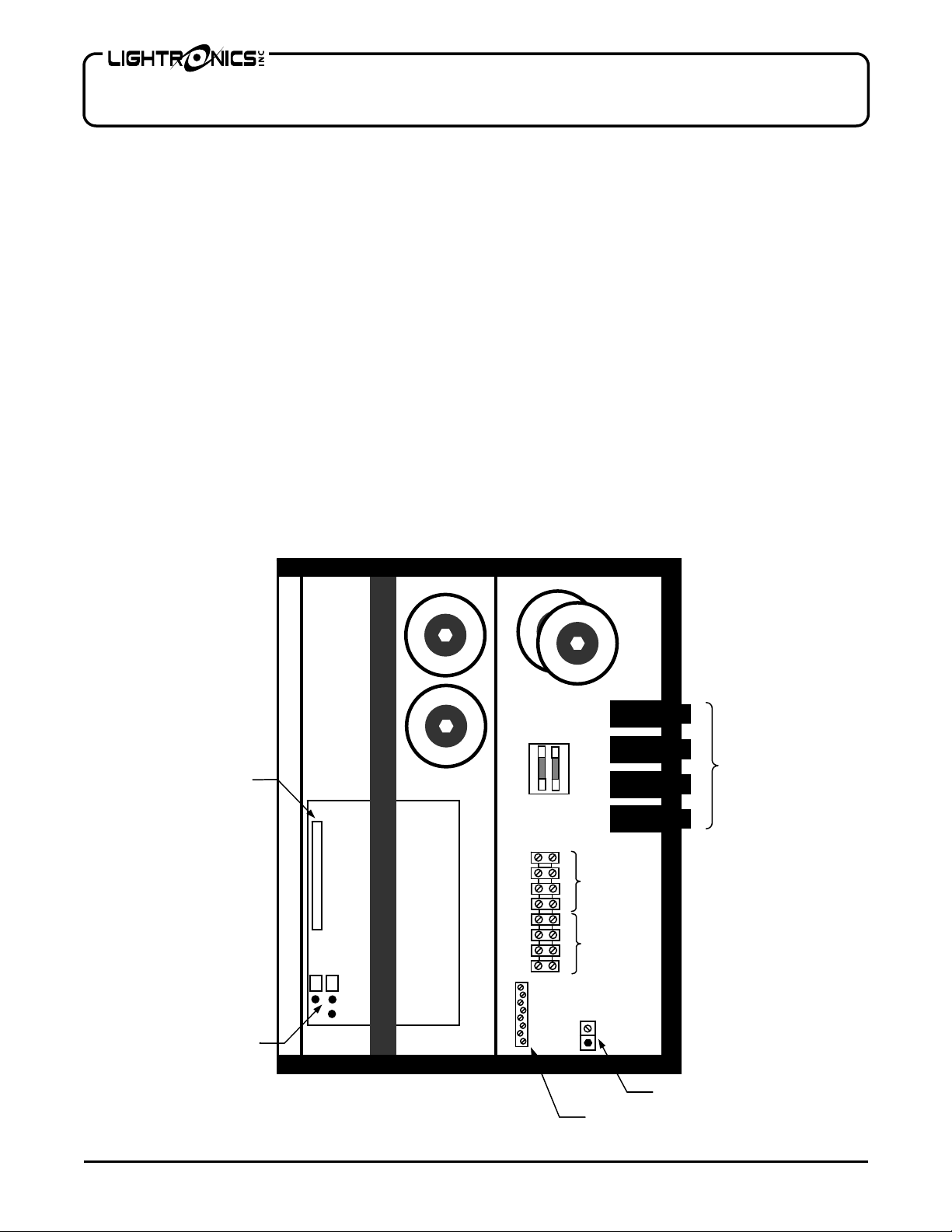
AT-402 FRONT VIEW (Cover Removed)
1/2AMP FUSE
AND SPARE
CIRCUIT
BOARD
1
2
LIGHTING
3
LOADS
4
1
120VAC
2
POWER IN
3
4
NEUTRALS
1
2
3
4
GROUNDS
CIRCUIT
BREAKERS
Page 2
Page 2 of 8
AT SERIES ARCHITECTURAL DIMMER
Revision 0.1 OWNERS MANUAL 08/29/2003
LOCATION AND MOUNTING
The unit is to be wall mounted using the mounting holes provided in the chassis. Orient the unit such that the
circuit board is in the lower left area of the chassis. The unit may (but is not required to be) spaced out from the
wall approx. 1 inch. This may be desirable if the unit must be used in a location with a high ambient temperature.
Standard sized knockout holes are provided in the top, bottom and right side of the chassis for wiring. Be sure
that the vent holes in the chassis and cover are not obstructed since they are needed for proper cooling.
INPUT POWER CONNECTIONS
WARNING
Make sure that all power is removed from feed circuits before proceeding with wiring.
Connect power input leads to the lower terminal strip positions as indicated on the terminal strip labels. A hot
feed line is needed for each channel. Associated NEUTRALS are to be connected to the NEUTRAL bar provided.
An earth ground is also needed. A ground lug is provided. The terminal strip connection torque specification is 16
lb.-in. max. The minimum wire size is AWG#12. Consult the applicable electrical codes for your location for exact
wire specifications. The power terminal connections are intended for copper wire only. This unit will work on
either single or three phase power. Any dimmer channel may get power from any phase.
LOAD CONNECTIONS
The AT Series dimmer is intended for incandescent lamp loads. You can connect up to 2400 Watts of lighting to
each channel. Connect lighting loads to the upper terminal strip positions as indicated by the label. The neutral
bar and ground lug may be used for lighting loads. The terminal strip connection torque specification is 16 lb.-in.
max.
REMOTE SWITCH CONNECTIONS
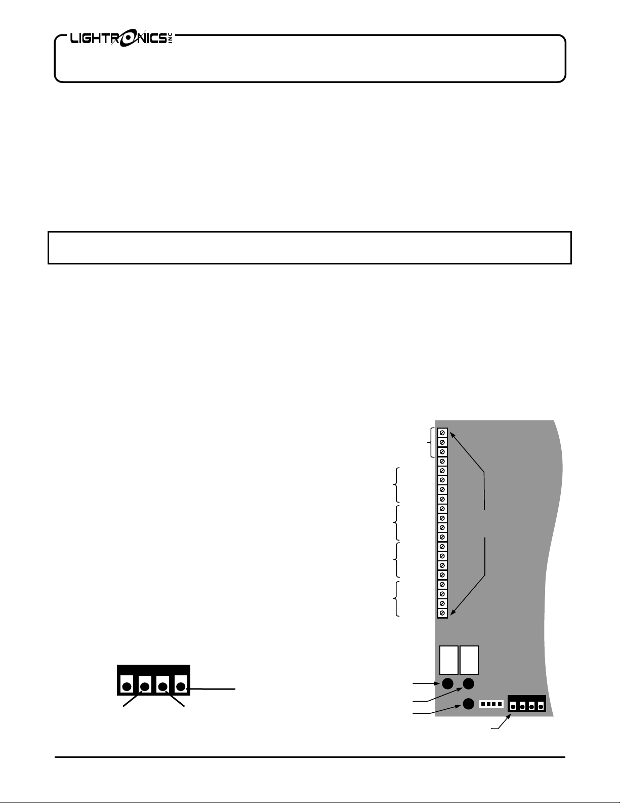
A control terminal strip located on left side of
the low voltage section of the printed circuit
board is provided for connecting external switch
control signals. In general, a common signal
(circuit ground) is sent from the terminal strip to
a momentary contact of a remotely located
switch. The switch closure is returned to other
positions on the AT-402 dimmer control
terminal strip to activate four preset channel
intensity levels for each of 4 lighting conditions
to be activated.
DMX CONNECTIONS
A 4 pin screw terminal connector is provided for
DMX signal input. It is located aprox. centered
along the bottom edge of the circuit board. The
connection details are shown below:
DMX DATA - DMX DATA +
DMX COMMON
Channel 1
Channel 2
Channel 3
Channel 4
Common
All On / Resume
Preset A
Preset B
Preset C
Preset D
Preset A
Preset B
Preset C
Preset D
Preset A
Preset B
Preset C
Preset D
Preset A
Preset B
Preset C
Preset D
NEXT
UP
DOWN
DMX CONNECTOR
Terminal Strip
www.lightronics.com
Lightronics Inc. 509 Central Drive Virginia Beach, VA 23454 tel 757 486 3588
CIRCUIT
CARD
Control
Page 3
Page 3 of 8
AT SERIES ARCHITECTURAL DIMMER
Revision 0.1 OWNERS MANUAL 08/29/2003
INITIAL SET UP
Set up of the AT Series dimmer is done using the 2 LED indicators and the 3 push buttons located at the bottom
left of the low voltage section of the the circuit board inside of the unit. Use these controls to set the unit to
operate correctly for the type of input power being used for the unit.
Set the Input Power Phase for each dimmer channel. This must be set correctly or dimmers will not operate
correctly.
LED SYMBOL FUNCTION VALUE
P2 Channel 2 Input power phase A, B, or C
P3 Channel 3 Input power phase A, B, or C
P4 Channel 4 Input power phase A, B, or C
For P2-P4, set to A, B, or C depending on which phase each channel gets its power from. For single phase
power set P2, P3, and P4 to "A".
SET UP FOR A SINGLE PHASE POWER INSTALLATION
Press the NEXT button repeatedly until P2 appears on the LED indicator. This tells the unit which phase circuit 2
is getting it's power from, hence P2 (phase - Channel 2). Use the UP/DOWN buttons to set the right hand
indicator to "A". Do the same for P3 and P4 (phase - Channel 3) (phase - Channel 4).
SET UP FOR A THREE PHASE POWER INSTALLATION
Hold down the NEXT button until P2 appears on the LED indicator. Use the UP/DOWN buttons to set the right
hand indicator to "B" or "C". If the unit does not fade smoothly between preset levels or some of the channels
seem to operate in an OFF/ON only fashion then you should change this setting to the other three phase choice
(B or C).
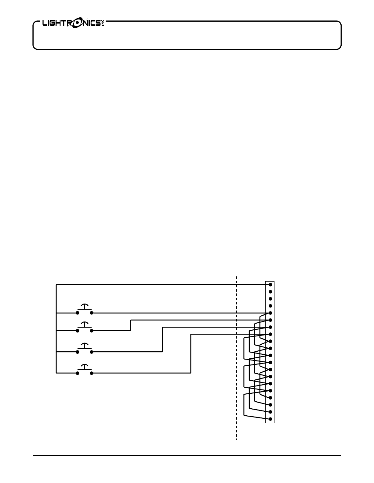
REMOTE SWITCH CONNECTIONS EXAMPLE
EXTERNAL SWITCHES
www.lightronics.com
Lightronics Inc. 509 Central Drive Virginia Beach, VA 23454 tel 757 486 3588
AT-402 CONTROL
TERMINAL STRIP
COMMON
COMMON
COMMON
ALL ON / RESUME
CH 1, PRESET A
CH 1, PRESET B
CH 1, PRESET C
CH 1, PRESET D
CH 2, PRESET A
CH 2, PRESET B
CH 2, PRESET C
CH 2, PRESET D
CH 3, PRESET A
CH 3, PRESET B
CH 3, PRESET C
CH 3, PRESET D
CH 4, PRESET A
CH 4, PRESET B
CH 4, PRESET C
CH 4, PRESET D
Page 4

Page 4 of 8
AT SERIES ARCHITECTURAL DIMMER
Revision 0.1 OWNERS MANUAL 08/29/2003
OPERATION
CIRCUIT BREAKERS
Some models of AT Series dimmers use circuit breakers. If it does - there is a 20 Amp magnetic circuit breaker for
each dimmer channel located on the right side of the unit. To operate a channel, the associated circuit breaker
must be closed. Channel numbers for the circuit breakers are labeled on the unit. If a circuit breaker will not
remain closed then there is an overload at the lamps for that channel which MUST be corrected before operation
can continue.
INDICATORS
There is a LED indicator for each channel on circuit board. They provide an indication of the current lighting
intensity for the associated channel.
DMX OPERATION
When a DMX Lighting Control console of controller is used with an AT series dimmer the dimmer will respond to
controller DMX channels 1 - 4. No additional settings are needed. If a valid DMX signal is provided to the unit - it
will override and lock out ALL remote switch closure operation.
REMOTE SWITCH CONTROL
GENERAL REMOTE SWITCH OPERATION - A SMALL THEATER EXAMPLE
During theater operation, the lighting is controlled by external momentary switch closures either manually or by
automated equipment. The AT-402 dimmer is designed to activate preset lighting conditions in response to these
controls.
A simple scenario is described in the following table. The table is for an installation where a four channel unit is
used. AT-402 dimmer channels 1 and 2 are connected to the stage lights and AT-402 dimmer channels 3 and 4
are connected to the house lights. The 3% intensity level shown for some of the settings in the table essentially
results in no light from the lamps but keeps the lamp filaments warm which extends the lamp life.
ACTIVITY or PRESET
HOUSE LIGHTING
Channel 1
HOUSE LIGHTING
Channel 2
STAGE LIGHTING
Channel 3
STAGE LIGHTING
Channel 4
A Opening and Seating 90% (5 sec. Fade) 90% (5 sec. Fade) 90% (5 sec. Fade) 90%(5 sec. Fade)
B Introduction 50% (15 sec. Fade) 50% (15 sec. Fade) 3% (15 sec. Fade) 3% (15 sec. Fade)
C Main Performance 3% (5 sec. fade) 3%(5 sec. fade) 3% 3%
D Closing 60% (10 sec. Fade) 60% (10 sec. fade) 3% 3%
MANUAL ALL ON / RESUME OPERATION
The "All On / Resume" control may be activated by momentary external switch closure between one of the
"Common" terminals and the "All On / Resume" terminal of the circuit board Control Terminal Strip. . This function
overrides other switched channel controls. It sets all channels to maximum intensity, and remains in effect until
the button is pushed again. At that time the unit will "Resume" normal operation (return to the intensity settings
provided by the other remote switch control signals).
www.lightronics.com
Lightronics Inc. 509 Central Drive Virginia Beach, VA 23454 tel 757 486 3588
Page 5

Page 5 of 8
AT SERIES ARCHITECTURAL DIMMER
Revision 0.1 OWNERS MANUAL 08/29/2003
PROGRAMMING THE UNIT:
The LED's will alternate between the FUNCTION (channel/preset level and preset fade) and its VALUE (intensity
and fade time). There are 2 digits and 3 buttons to control everything. Press the NEXT button to advance through
each FUNCTION. Press the UP and DOWN buttons to change the VALUE for the alternately displayed
FUNCTION.
Note that the 100% intensity value on the LED display is indicated by "FL" (full).
SYMBOL FUNCTION VALUE
1A Channel 1 Preset A intensity 0-100% intensity
1b Channel 1 Preset B intensity 0-100% intensity
1C Channel 1 Preset C intensity 0-100% intensity
1d Channel 1 Preset D intensity 0-100% intensity
2A Channel 2 Preset A intensity 0-100% intensity
2b Channel 2 Preset B intensity 0-100% intensity
2C Channel 2 Preset C intensity 0-100% intensity
2d Channel 2 Preset D intensity 0-100% intensity
3A Channel 3 Preset A intensity 0-100% intensity
3b Channel 3 Preset B intensity 0-100% intensity
3C Channel 3 Preset C intensity 0-100% intensity
3d Channel 3 Preset D intensity 0-100% intensity
4A Channel 4 Preset A intensity 0-100% intensity
4b Channel 4 Preset B intensity 0-100% intensity
4C Channel 4 Preset C intensity 0-100% intensity
4d Channel 4 Preset D intensity 0-100% intensity
1 Channel 1 Up fade time 1-99 seconds (applied to all presets)
1 Channel 1 Down fade time 1-99 seconds (applied to all presets)
2 Channel 2 Up fade time 1-99 seconds (applied to all presets)
2 Channel 2 Down fade time 1-99 seconds (applied to all presets)
3 Channel 3 Up fade time 1-99 seconds (applied to all presets)
3 Channel 3 Down fade time 1-99 seconds (applied to all presets)
4 Channel 4 Up fade time 1-99 seconds (applied to all presets)
4 Channel 4 Down fade time 1-99 seconds (applied to all presets)
You can STOP HERE, or continue and set the individual up/down fade times. If individual
times do not need to be set then proceed to P2-P4 Channel Input power phase selection.
www.lightronics.com
Lightronics Inc. 509 Central Drive Virginia Beach, VA 23454 tel 757 486 3588
Page 6

Page 6 of 8
AT SERIES ARCHITECTURAL DIMMER
Revision 0.1 OWNERS MANUAL 08/29/2003
TO SET THE INDIVIDUAL UP/DOWN FADE TIMES (or skip this section) These settings will over-ride the fade
up/down settings in the previous section.
SYMBOL FUNCTION VALUE
.A1 Channel 1, Preset A - up fade time 1-99 seconds
A1 Channel 1, Preset A - down fade time 1-99 seconds
.b1 Channel 1, Preset B - up fade time 1-99 seconds
b1 Channel 1, Preset B - down fade time 1-99 seconds
.C1 Channel 1, Preset C - up fade time 1-99 seconds
C1 Channel 1, Preset C - down fade time 1-99 seconds
.d1 Channel 1, Preset D - up fade time 1-99 seconds
d1 Channel 1, Preset D - down fade time 1-99 seconds
.A2 Channel 2, Preset A - up fade time 1-99 seconds
A2 Channel 2, Preset A - down fade time 1-99 seconds
.b2 Channel 2, Preset B - up fade time 1-99 seconds
b2 Channel 2, Preset B - down fade time 1-99 seconds
.C2 Channel 2, Preset C - up fade time 1-99 seconds
C2 Channel 2, Preset C - down fade time 1-99 seconds
.d2 Channel 2, Preset D - up fade time 1-99 seconds
d2 Channel 2, Preset D - down fade time 1-99 seconds
.A3 Channel 3, Preset A - up fade time 1-99 seconds
A3 Channel 3, Preset A - down fade time 1-99 seconds
.b3 Channel 3, Preset B - up fade time 1-99 seconds
b3 Channel 3, Preset B - down fade time 1-99 seconds
.C3 Channel 3, Preset C - up fade time 1-99 seconds
C3 Channel 3, Preset C - down fade time 1-99 seconds
.d3 Channel 3, Preset D - up fade time 1-99 seconds
d3 Channel 3, Preset D - down fade time 1-99 seconds
.A4 Channel 4, Preset A - up fade time 1-99 seconds
A4 Channel 4, Preset A - down fade time 1-99 seconds
.b4 Channel 4, Preset B - up fade time 1-99 seconds
b4 Channel 4, Preset B - down fade time 1-99 seconds
.C4 Channel 4, Preset C - up fade time 1-99 seconds
C4 Channel 4, Preset C - down fade time 1-99 seconds
.d4 Channel 4, Preset D - up fade time 1-99 seconds
d4 Channel 4, Preset D - down fade time 1-99 seconds
www.lightronics.com
Lightronics Inc. 509 Central Drive Virginia Beach, VA 23454 tel 757 486 3588
Page 7

Page 7 of 8
A
A
A
A
AT SERIES ARCHITECTURAL DIMMER
Revision 0.1 OWNERS MANUAL 08/29/2003
MAINTENANCE
WARNING! RISK OF ELECTRICAL SHOCK
There are lethal voltages present in this product when power is applied to its feed circuits.
The cabinet should be opened only by a qualified electrician.
The only user servicable part in the AT Series dimmer is the Type ABC, ½ Amp, 250 Volt, fast acting fuse. A
spare fuse is provided with the unit. The fuse may be replaced ONLY with an identical fuse.
WARNING !
Make sure that all power is removed from feed circuits before changing the fuse.
Service by other than the manufacturers authorized agents may void your warranty.
The best way to prolong the life of your unit is to keep it cool, clean, and dry. It is important that the cooling intake
and exit vent holes are clean and unobstructed.
MODEL NUMBERS AND CONFIGURATION
The table below shows the number of channels and circuit breaker information for each model number.
MODEL NUMBER DESCRIPTION
T-402 4 Channels
T-302 3 Channels
T-202 2 Channels
T-102 1 Channel
A suffix "B" will appear at the end of the model number if the unit containschannel circuit breakers.
An additional suffix may also appear in the model number. This suffix is "/2" and indicated that the unit is for
240/480VAC applications.
For one and two channel versions, only the components, indicators, and connection points for the applicable
channels will be present in the unit.
www.lightronics.com
Lightronics Inc. 509 Central Drive Virginia Beach, VA 23454 tel 757 486 3588
Page 8

W
Y
All Lightronics products are warranted for a period of TWO YEARS from the date of
purchase against defects in materials and workmanship.
This warranty is subject to the following restrictions and conditions:
A) If service is required, you may be asked to provide proof of purchase from an
authorized Lightronics dealer.
B) This warranty is valid only for the original purchaser of the unit.
C) This warranty does not apply to damage resulting from abuse, misuse, accidents,
shipping, and repairs or modifications by anyone other than an authorized Lightronics
service representative.
D) This warranty is void if the serial number is removed, altered or defaced.
E) This warranty does not cover loss or damage, direct or indirect arising from the use
or inability to use this product.
F) Lightronics reserves the right to make any changes, modifications, or updates as
deemed appropriate by Lightronics to products returned for service. Such changes
may be made without prior notification to the user and without incurring any
responsibility or liability for modifications or changes to equipment previously
supplied. Lightronics is not responsible for supplying new equipment in accordance
with any earlier specifications.
G) This warranty is the only warranty either expressed, implied, or statutory, upon which
the equipment is purchased. No representatives, dealers or any of their agents are
authorized to make any warranties, guarantees, or representations other than
expressly stated herein.
H) This warranty does not cover the cost of shipping products to or from Lightronics for
service.
ARRANT
Lightronics Inc. 509 Central Drive, Virginia Beach VA 23454 (757) 486 3588
 Loading...