

Page 1
COMPACT DMX DIMMER
AS-42D
Version 2.0 02/14/2005 Page 1 of 5
Please take a moment to read this manual
before operating the AS-42D DImmer
IMPORTANT:
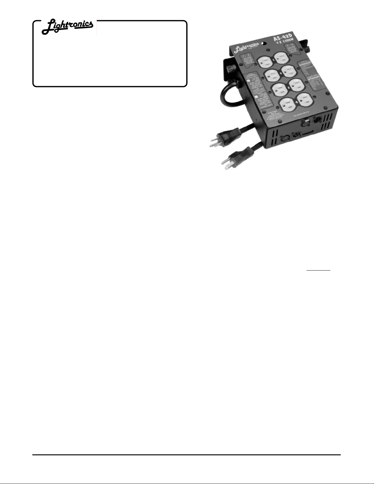
DESCRIPTION
The AS-42D is a compact 4 channel light dimmer. It has a maximum capacity of 1200 Watts per channel and
maximum total load capacity of 4800 Watts. It is supplied with 2 input power cord stubs which may be connected
to 2 different 120 VAC power phases. The AS - 42D is intended for INDOOR USE ONLY. The unit operates
using the USITT DMX-512 protocol or an industry standard three wire multiplex protocol. The AS-42D may be
operated in a relay (non-dim) mode. The unit will also function as a chaser and has several preset chase patterns
which may be used.
INSTALLATION
LOCATION: Locate the unit in a well ventilated area away from moisture and heat. Two ½” holes are provided
on the dimmer top cover to install a lighting bar pipe clamp and suitable safety cables.
POWER CONNECTIONS: Extending from the chassis are two 20 amp line cords for connection to 2
separate
120 VAC grounded services in any phase combination. Total capacity of the AS-42D is 4800 watts.
LOAD CONNECTIONS: There are 4 numbered duplex outlets on the top of the unit. Each provides 2
connections for one of the output channel. You can connect up to 1200 Watts of lighting to each channel.
STAGE PIN OUTPUT CONNECTOR OPTION: There are 4 numbered female stage pin connectors on the top of
the unit. One connection is provided for each output channel. Wiring information for the stagepin connectors is
shown on the top of the unit.
CONTROL SIGNAL CONNECTIONS:
FOR MULTIPLEX OPERATION: The male three pin XLR connector on the unit end panel conne cts to the control
console. The female connector is for connection to additional dimmers. The AS-42D dimmer is compatible with
the Lightronics and NSI/Sunn three wire multiplexed protocol. If you have older Lightronics dimmers which run in
the obsolete Lightronics mode only, contact Lightronics for information on changing the mode. When using
multiple dimmers, ALL dimmers MUST be in the SAME mode.
FOR DMX-512 OPERATION: The male five pin XLR connector on the unit end panel connects to the control
console. The female connector is for connection to additional dimmers. The AS-42D dimmer is compatible with
the USITT DMX-512 protocol. If both multiplex and DMX signals are available to the unit - it will automatically
lock on to the DMX signal. Note that the DMX standard does not provide for console power via the dimmer chain.
Therefore the DMX console used with AS-42D dimmers must be powered by other means.
www.lightronics.com
Lightronics Inc. 509 Central Drive, Virginia Beach, VA 23454 Tel: 757 486 3588
Page 2
Page 2 of 5
AS-42D COMPACT DMX DIMMER
Version 2.0 OWNERS MANUAL 02/14/2005
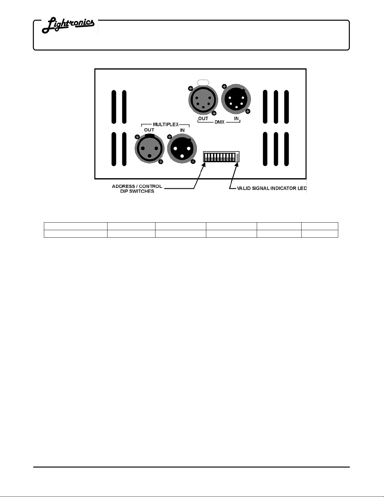
AS-42D END VIEW
CONTROL SIGNAL WIRING:
Connector Pin # 1 2 3 4 5
LMX-128 (multiplex) LMX Common Console Power Multiplex Signal Not Used Not Used
DMX-512 DMX Common DMX Data - DMX Data + Not Used Not Used
OPERATION
NORMAL MODE (non-chaser)
A green LED in the end panel will indicate that a valid control signal (DMX or multiplex) is applied to the unit.
A DIP switch block on the end panel selects the starting channel number of the dimmer. The 7 right hand
switches control this function. For example, if all switch positions are down - the dimmer will respond to channels
1-4. Moving the switch position on the far right up will set the dimmer to respond to channels 5-8. A complete
table of channel assignments is provided in this manual.. You can address up to 512 channels using DMX control
and up to 128 channels with multiplex control.
RELAY MODE: Pairs of channels (1/2 and/or 3/4) may be switched into the relay mode. In this mode the output
of these channels will be either off or full on depending on the control console channel setting. The trip point for
turn on is aprox. 50%. The 2 left hand switches on the DIP switch block control relay mode channel selection.
CHASER MODE:
When operating in the chaser mode the AS-42D becomes independent of the control console and othe r dimmers.
The green LED indicator is OUT when in the chaser mode. Chaser mode is turned on and off by one of the DIP
switches on the end of the unit. A diagram on the unit cover unit shows the switch settings for chaser operation.
Eight different chaser patterns are available. A “bounce” condition may be used on several of the chase patterns
by setting one of the DIP switches. The bounce condition causes the chase pattern to run in alternating
directions.
The chase step time may be controlled for up to 64 seconds per step. Step fade time is proportional to the step
time. If a channel is in the relay mode during chaser operation - it will “snap” on and off (zero fade time). The
tables below show the details of chaser settings.
www.lightronics.com
Lightronics Inc. 509 Central Drive, Virginia Beach, VA 23454 Tel: 757 486 3588
Page 3

Page 3 of 5
•
AS-42D COMPACT DMX DIMMER
Version 2.0 OWNERS MANUAL 02/14/2005
ADDRESS AND CONTROL SWITCH SETTINGS
NORMAL MODE SWITCH FUNCTIONS
RELAY C/D
RELAY A/B
ADDRESS
NORMAL/CHASER
(down for normal)
CHASER MODE SWITCH FUNCTIONS
RELAY C/D
RELAY A/B
BOUNCE
CHASER CHASER
PATTERN TIMING
NORMAL/CHASER
(up for chaser)
CHASER PATTERN SELECTION
SWITCHES PATTERN
4 chan. sequence
4 chan. build
4 chan. build/unbuild
4 chan. random
SWITCHES PATTERN
3 chan. sequence +
3 chan. build
3 chan. build/unbuild
2 chan. alternating
CHASER TIMING SELECTION
SWITCHES STEP TIME (Duration)
.5 seconds
1.0 seconds
2 seconds
4 seconds
SWITCHES STEP TIME (Duration)
8 seconds
16 seconds
32 seconds
64 seconds
MAINTENANCE AND REPAIR
TROUBLESHOOTING
• Check that you have power applied to the dimmer.
• Check that all light fixtures are functional.
• Check the fuses.
Check the multiplex and/or DMX cable.
• Check the settings of the dimmer DIP switches.
• Check the console setup for correct patching.
REPAIR
The only user serviceable parts are externally accessible fuses. Replace fuses ONLY with 10 Amp, 250VAC, fast
blow fuses. Internal service on the unit by other than Lightronics authorized agents will void the warranty.
If service is required, contact the dealer from whom you purchased the dimmer, or Lightronics, Service
Department, 509 Central Drive, Virginia Beach, VA 23454. Tel: 757 486 3588.
www.lightronics.com
Lightronics Inc. 509 Central Drive, Virginia Beach, VA 23454 Tel: 757 486 3588
Page 4
Page 4 of 5
AS-42D COMPACT DMX DIMMER
Version 2.0 OWNERS MANUAL 02/14/2005
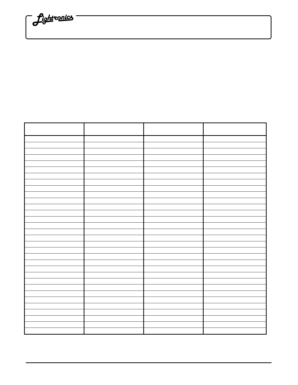
CHANNEL ASSIGNMENT SETTINGS
The DIP Switch Setting column shows the positions of the DIP switches on the dimmer. The Start Channel
column shows the resulting channel assignment for the first channel of the dimmer
All Lightronics products using DIP switches for address assignments conform to this table. Some dimmers cannot
be set to all 512 channels and will have fewer switches than are shown in the table. If this is the case then match
the right end switches in the table to your dimmer switches. NOTE: Some control consoles can be programmed
or "patched" to alter their channel order. You may get unexpected results if you are not aware of the console
patch condition when you assign channels at a dimmer.
EXAMPLE: If a dimmer's DIP switches are set to
to console channel 173. The remaining dimmer channels will respond to console channels 174, 175, 176 …etc.
DIP Switch
Setting
ШШШШШШШ
ШШШШШШГ
ШШШШШГШ
ШШШШШГГ
ШШШШГШШ
ШШШШГШГ
ШШШШГГШ
ШШШШГГГ
ШШШГШШШ
ШШШГШШГ
ШШШГШГШ
ШШШГШГГ
ШШШГГШШ
ШШШГГШГ
ШШШГГГШ
ШШШГГГГ
ШШГШШШШ
ШШГШШШГ
ШШГШШГШ
ШШГШШГГ
ШШГШГШШ
ШШГШГШГ
ШШГШГГШ
ШШГШГГГ
ШШГГШШШ
ШШГГШШГ
ШШГГШГШ
ШШГГШГГ
ШШГГГШШ
ШШГГГШГ
ШШГГГГШ
ШШГГГГГ
Start
Channel
1
5
9
13
17
21
25
29
33
37
41
45
49
53
57
61
65
69
73
77
81
85
89
93
97
101
105
109
113
117
121
125
DIP Switch
Setting
ШГШШШШШ
ШГШШШШГ
ШГШШШГШ
ШГШШШГГ
ШГШШГШШ
ШГШШГШГ
ШГШШГГШ
ШГШШГГГ
ШГШГШШШ
ШГШГШШГ
ШГШГШГШ
ШГШГШГГ
ШГШГГШШ
ШГШГГШГ
ШГШГГГШ
ШГШГГГГ
ШГГШШШШ
ШГГШШШГ
ШГГШШГШ
ШГГШШГГ
ШГГШГШШ
ШГГШГШГ
ШГГШГГШ
ШГГШГГГ
ШГГГШШШ
ШГГГШШГ
ШГГГШГШ
ШГГГШГГ
ШГГГГШШ
ШГГГГШГ
ШГГГГГШ
ШГГГГГГ
ШГШГШГГ then the first channel of the dimmer will respond
Start
Channel
129
133
137
141
145
149
153
157
161
165
169
173
177
181
185
189
193
197
201
205
209
213
217
221
225
229
233
237
241
245
249
253
DIP Switch
Setting
ГШШШШШШ
ГШШШШШГ
ГШШШШГШ
ГШШШШГГ
ГШШШГШШ
ГШШШГШГ
ГШШШГГШ
ГШШШГГГ
ГШШГШШШ
ГШШГШШГ
ГШШГШГШ
ГШШГШГГ
ГШШГГШШ
ГШШГГШГ
ГШШГГГШ
ГШШГГГГ
ГШГШШШШ
ГШГШШШГ
ГШГШШГШ
ГШГШШГГ
ГШГШГШШ
ГШГШГШГ
ГШГШГГШ
ГШГШГГГ
ГШГГШШШ
ГШГГШШГ
ГШГГШГШ
ГШГГШГГ
ГШГГГШШ
ГШГГГШГ
ГШГГГГШ
ГШГГГГГ
Start
Channel
257
261
265
269
273
277
281
285
289
293
297
301
305
309
313
317
321
325
329
333
337
341
345
349
353
357
361
365
369
373
377
381
DIP Switch
Setting
ГГШШШШШ
ГГШШШШГ
ГГШШШГШ
ГГШШШГГ
ГГШШГШШ
ГГШШГШГ
ГГШШГГШ
ГГШШГГГ
ГГШГШШШ
ГГШГШШГ
ГГШГШГШ
ГГШГШГГ
ГГШГГШШ
ГГШГГШГ
ГГШГГГШ
ГГШГГГГ
ГГГШШШШ
ГГГШШШГ
ГГГШШГШ
ГГГШШГГ
ГГГШГШШ
ГГГШГШГ
ГГГШГГШ
ГГГШГГГ
ГГГГШШШ
ГГГГШШГ
ГГГГШГШ
ГГГГШГГ
ГГГГГШШ
ГГГГГШГ
ГГГГГГШ
ГГГГГГГ
Channel
Start
385
389
393
397
401
405
409
413
417
421
425
429
433
437
441
445
449
453
457
461
465
469
473
477
481
485
489
493
497
501
505
509
www.lightronics.com
Lightronics Inc. 509 Central Drive, Virginia Beach, VA 23454 Tel: 757 486 3588
Page 5

WARRANTY
All Lightronics products are warranted for a period of TWO/FIVE YEARS from the date of
purchase against defects in materials and workmanship.
This warranty is subject to the following restrictions and conditions:
A) If service is required, you may be asked to provide proof of purchase from an authorized
Lightronics dealer.
B) The FIVE YEAR WARRANTY is only valid if the warranty card is returned to Lightronics
accompanied with a copy of the original receipt of purchase within 30 DAYS of the
purchase date, if not then the TWO YEAR WARRANTY applies. Warranty is valid only for
the original purchaser of the unit.
C) This warranty does not apply to damage resulting from abuse, misuse, accidents, shipping,
and repairs or modifications by anyone other than an authorized Lightronics service
representative.
D) This warranty is void if the serial number is removed, altered or defaced.
E) This warranty does not cover loss or damage, direct or indirect arising from the use or
inability to use this product.
F) Lightronics reserves the right to make any changes, modifications, or updates as deemed
appropriate by Lightronics to products returned for service. Such changes may be made
without prior notification to the user and without incurring any responsibility or liability for
modifications or changes to equipment previously supplied. Lightronics is not responsible
for supplying new equipment in accordance with any earlier specifications.
G) This warranty is the only warranty either expressed, implied, or statutory, upon which the
equipment is purchased. No representatives, dealers or any of their agents are authorized
to make any warranties, guarantees, or representations other than expressly stated herein.
H) This warranty does not cover the cost of shipping products to or from Lightronics for
service.
I) Lightronics Inc. reserves the right to make changes as deemed necessary to this warranty
without prior notification.
Page 6

Lightronics Inc. 509 Central Drive Virginia Beach, VA 23454 20050125
 Loading...