

Page 1 of 3
AK SERIES ARCHITECTURAL REMOTE STATION
Version 0.1 OWNERS MANUAL 08/08/2011
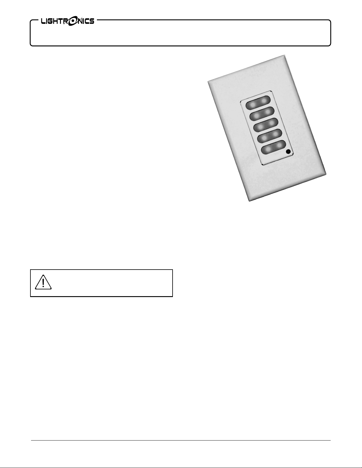
GENERAL DESCRIPTION
AK Series remote units are wall mounted, multiscene
remotes for use with the Lightronics AR-1202
architectural dimmer and certain other Lightronics
products. Each button activates a complete lighting
scene. LED indicators show which scene active .
There are currently three models available:
AK-1005 5 Scenes
AK-1003 3 Scenes
AK-1002 2 Scenes
AK Series units fit into standard single gang wall
switch boxes. They communicates with the AR-1202
via a 4 wire bus which will accommodate several
remotes and other controls. All wiring is low voltage.
The units generally operate in an exclusive mode
where only one scene can be active at a time. Each
scene may be toggled on and off. When a scene is
selected, the AR-1202 circuits fade, at a user controlled
rate, to the setting for that scene.
Scenes activated by these remotes are actually set up
and stored in the AR-1202 dimmer. The remotes only
tell the AR-1202 which scene(s) to activate.
INSTALLATION
Remove all power from the AR-1202
before making connections
CAUTION
AK Series units connect to the AR-1202 via a shielded
4 conductor cable arranged as 2 twisted pairs. One pair
connects to the DATA - and DATA + signals. The
other pair carries the common and power.
See the diagram
"CONNECTOR WIRING"
for details.
SINGLE UNIT: Connect the 4 cable wires to the
screw down terminals on the back of the unit. Connect
the cable shield to the REMOTE COMMON terminal.
The other end of the cable connects to a small terminal
strip inside the AR-1202 dimmer. Refer to the AR1202 Owners Manual for complete wiring details.
AK-1005
MULTIPLE UNITS: Follow the instructions for a
single unit for the first AK Series remote. Connect the
terminals of the second unit to the corresponding
terminals of the of the first unit (create a "daisy
chain").
Additional units can be added in the same manner.
Do not make multiple "home runs" to the AR-1202 or
create a "star network".
OPERATION
SCENE SETUP
Scenes to be activated by an AK Series remote must
have already been created and stored in the AR-1202
dimmer. See the AR-1202 Owners Manual for
instructions on programming scenes.
AK Series remotes are used with AR-1202 scenes
starting at scene one (the top button). The remaining
buttons use the next consecutive numbered scenes. If
multiple units are used, they will ALL use scenes
starting at scene one.
It is possible to make AK Series remotes operate with
other scenes but the unit must be ordered with special
factory programming to do so.
www.lightronics.com
Lightronics Inc. 509 Central Drive Virginia Beach, VA 23454 tel 757 486 3588

Page 2 of 3
AK SERIES ARCHITECTURAL REMOTE STATION
Version 0.1 OWNERS MANUAL 08/08/2011
GENERAL OPERATION
No setup or turn on procedure is needed. When the
AR-1202 dimmer is powered on, the AK Series
remotes will also be powered.
If communication with the AR-1202 cannot be
established, a remote will appear to be repeatedly
scanning through all scenes.
MAINTENANCE AND REPAIR
TROUBLESHOOTING
1. Check cables and the connections at both ends.
2. If the unit is being used with a AR-1202 system ensure that one (and only one) of the AR-1202
dimmer(s) in the system is set to UNIT
ADDRESS 00
OWNER MAINTENANCE
There are no user serviceable parts in the unit. Service
by other than Lightronics authorized agents will void
your warranty.
OPERATING AND MAINTENANCE ASSISTANCE
Dealer and Lightronics Factory personnel can help you
with operation or maintenance problems. Please read
the applicable parts of this manual before calling for
assistance.
If service is required - contact the dealer from whom
you purchased the unit or contact the Lightronics,
Service Dept..
TO
AR-1202
CONNECTOR WIRING
SHIELD
REMOTE DATA +
REMOTE DATA -
REMOTE COMMON
-
-
AK-1005
Rear View
J101
www.lightronics.com
Lightronics Inc. 509 Central Drive Virginia Beach, VA 23454 tel 757 486 3588
Y
WARRANT
All Lightronics products are warranted for a period of TWO/FIVE YEARS from the date of
purchase against defects in materials and workmanship.
This warranty is subject to the following restrictions and conditions:
A) If service is required, you may be asked to provide proof of purchase from an authorized
Lightronics dealer.
B) The FIVE YEAR WARRANTY is only valid if the warranty card is returned to Lightronics
accompanied with a copy of the original receipt of purchase within 30 DAYS of the
purchase date, if not then the TWO YEAR WARRANTY applies. Warranty is valid only for
the original purchaser of the unit.
C) This warranty does not apply to damage resulting from abuse, misuse, accidents, shipping,
and repairs or modifications by anyone other than an authorized Lightronics service
representative.
D) This warranty is void if the serial number is removed, altered or defaced.
E) This warranty does not cover loss or damage, direct or indirect arising from the use or
inability to use this product.
F) Lightronics reserves the right to make any changes, modifications, or updates as deemed
appropriate by Lightronics to products returned for service. Such changes may be made
without prior notification to the user and without incurring any responsibility or liability for
modifications or changes to equipment previously supplied. Lightronics is not responsible
for supplying new equipment in accordance with any earlier specifications.
G) This warranty is the only warranty either expressed, implied, or statutory, upon which the
equipment is purchased. No representatives, dealers or any of their agents are authorized
to make any warranties, guarantees, or representations other than expressly stated herein.
H) This warranty does not cover the cost of shipping products to or from Lightronics for
service.
I) Lightronics Inc. reserves the right to make changes as deemed necessary to this warranty
without prior notification.
Lightronics Inc. 509 Central Drive Virginia Beach, VA 23454 20050125

www.lightronics.com
Lightronics Inc. 509 Central Drive Virginia Beach, VA 23454 tel 757 486 3588
 Loading...