

Page 1
AB0602D
ARCHITECTURAL BALLAST DRIVER
Version 0.10
Date 06/25/2012
www.lightronics.com
Lightronics Inc. 509 Central Drive Virginia Beach, Va 234354 757 486 3588
Page 2

Page 2 of 10
AB0602D ARCHITECTURAL BALLAST DRIVER
Version 0.10 OWNERS MANUAL 06/25/2012
DESCRIPTION AND FEATURES
The AB-0602D is a 6 circuit, 2400 Watts per circuit
ballast driver intended for dimmable fluorescent and
LED fixtures which use a switched 120VAC hot
feed and a 0 - 10 VDC analog control signal to
operate them. A three circuit version (AB-0302D) is
also available and operates identically.
The AB-0602D can also be used as a conventional
relay pack by using only the switched hot feed
controls without the 0 - 10VDC analog signal.
EXTERNAL CONTROLS
The AB-0602D can communicate with remotely
located control equipment in several ways.
A USITT DMX-512 protocol bus is provided so the
unit may be used with any DMX lighting console.
The AB-0602D is fully patchable with respect to the
DMX bus.
The AB-0602D may also be controlled by several
types of wall mounted smart remote stations. Smart
remotes communicate with the unit by way of a low
voltage RS-485 bus. This bus is completely separate
from the DMX bus. Smart remotes are used to
activate preset scenes which have been stored in the
AB-0602D. There are several types of smart remote
stations. Multiple smart remotes of the same or
different types may be chained together on the RS485 bus. The same RS-485 bus may be chained to
multiple AB-0602D units.
The AB-0602D may additionally be controlled by an
arrangement of one or more momentary switches
(simple remotes). The switches may be used to
control a specific set of eight scenes which are
stored in the AB-0602D.
INSTALLATION
PHYSICAL LOCATION
The unit is intended for
INDOOR USE ONLY
and
should not be subjected to excessive moisture or
heat. The unit should be installed where a supply of
circulating air is available. The AB-0602D is
designed to be wall mounted in a equipment room or
electrical distribution area.
The ambient air in the installation area should be
below 86 deg F.
Provide spacing between the unit and other
equipment to allow air flow around the unit. See the
DIMENSIONS AND LOCATIONS
diagram for more
information about mounting the unit.
POWER REQUIREMENTS
DANGER
RISK OF FIRE
DANGER
RISK OF ELECTRIC SHOCK
The internal AB-0602D circuitry requires a 120VAC
line feed. The circuitry is fused with a 1/2 Amp fast
acting 1 1/4" x 1/4", 250V fast acting fuse.
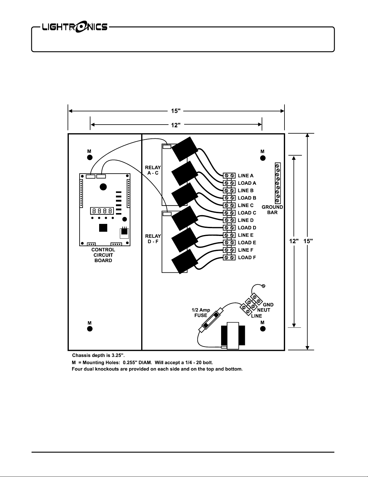
SWITCHED HOTS
A separate 120 VAC line feed is needed for each of
the six switched hot loads (A - F). The maximum
load for each load is 2400 Watts (20 Amps).
These connections are made on a terminal strip
inside the AB-0602D. The diagram
AND LOCATIONS
shows the connection details.
DIMENSIONS
A grounding bar is also provided.
ANALOG (0-10VDC) OUTPUT CONNECTIONS
Connectors with screw down terminals are provided
on the control circuit board for the 0 -10VDC analog
output signals. Specific wiring connection point
information is shown in the diagram
AND ANALOG CONNECTIONS.
CONTROL SIGNAL CONNECTIONS
CONTROL
Connectors with screw down terminals are provided
for connection to DMX consoles, smart remotes, and
simple remote stations. Specific wiring connection
point information for all external control signals is
shown in the diagram
CONNECTIONS.
CONTROL AND ANALOG
www.lightronics.com
Lightronics Inc. 509 Central Drive Virginia Beach, Va 234354 757 486 3588
Page 3
Page 3 of 10
AB0602D ARCHITECTURAL BALLAST DRIVER
Version 0.10 OWNERS MANUAL 06/25/2012
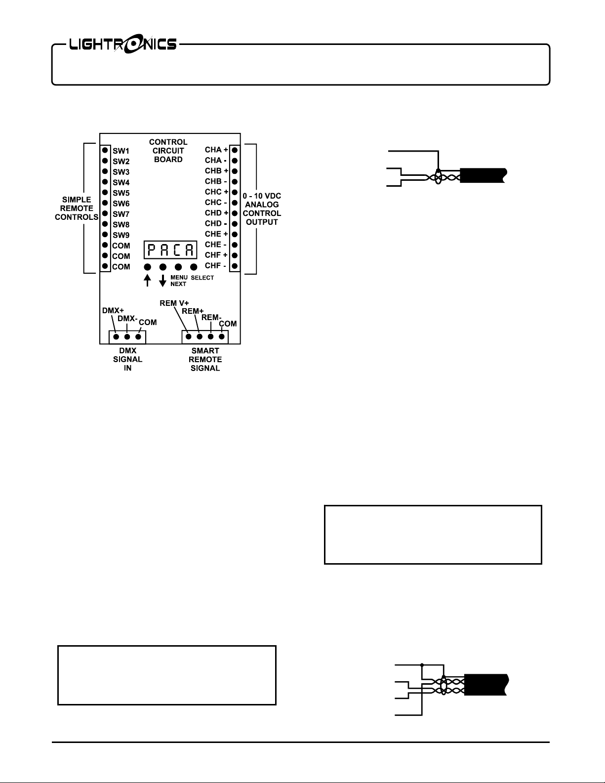
CONTROL AND ANALOG CONNECTIONS
DMX CONSOLE CONNECTIONS
DMX console signals to the AB-0602D should be
transmitted over a twisted pair, shielded, low
capacitance cable. A DMX console transmits from
a female, 5 Pin XLR Connector.
See the
CONTROL AND ANALOG CONNECTIONS
diagram for specific connection details.
DMX TERMINATION
A DMX bus should be terminated (only) at the last
receiving device on the chain. This is done by
connecting a 120 ohm, 1/4 watt resistor across the
DMX DATA - and DMX DATA + lines.
DMX CONNECTION ARRANGEMENT
A DMX bus should be daisy chained to all its
receiving units. It should NOT be connected in a star
arrangement with multiple "home runs".
REMOVE ALL POWER FROM THE AB-0602D
BEFORE MAKING OR CHANGING DMX
CONSOLE CONNECTIONS.
CAUTION
CONDUCTOR ARRANGEMENT FOR
TWISTED PAIR, SHIELDED CABLE
DMX CABLE
Common
DMX Data -
DMX Data +
Shield
SMART REMOTE CONNECTIONS
There are two types of smart remotes (push button
and fader) which can be used with the AB-0602D.
There are multiple models of each type. They all
connect to a common RS-485 bus which is
controlled by a AB-0602D. Additional AB-0606D
units may also be connected on the same bus. One of
them will be set as the master controller by making
UNIT ID ADDRESS ASSIGNMENTS
.
Smart remote signals to the AB-0602D are
transmitted over a two twisted pair, shielded, low
capacitance cable. One pair carries the RS-485
signal and the other provides a low voltage power
and common to the remotes.
A smart remote bus should be daisy chained to all its
receiving units. It should NOT be connected in a star
arrangement with multiple "home runs".
Each smart remote has a 4 pin connector with screw
down terminals to connect to the RS-485 bus. You
must get the exact wiring pinout information for the
remote unit from its owners manual.
REMOVE ALL POWER FROM THE AB-0602D
BEFORE MAKING OR CHANGING SMART
See the
REMOTE CONNECTIONS.
CONTROL AND ANALOG CONNECTIONS
CAUTION
diagram for specific connection details.
SMART REMOTES CABLE CONDUCTOR
ARRANGEMENT FOR DUAL TWISTED PAIR,
SHIELDED CABLE
Common
Data -
Data +
Voltage +
Shield
www.lightronics.com
Lightronics Inc. 509 Central Drive Virginia Beach, Va 234354 757 486 3588
Page 4

Page 4 of 10
AB0602D ARCHITECTURAL BALLAST DRIVER
Version 0.10 OWNERS MANUAL 06/25/2012
SIMPLE REMOTE CONNECTIONS
REMOVE ALL POWER FROM THE AB-0602D
BEFORE MAKING OR CHANGING SIMPLE
REMOTE CONNECTIONS.
CAUTION
Scenes 1 - 8 (stored in the AB-0602D) may be used
by simple remotes. A BLACKOUT function may
also be accessed. A simple remote is any switch that
can provide a momentary contact closure which can
be applied to a specific pin on the AB-0602D simple
remote controls connector.
See the
CONTROL AND ANALOG CONNECTIONS
diagram for specific connection details. The three
COM
(commons) pins are electrically tied together.
A SIMPLE REMOTE COMMON is routed to the
remote switch. When the switch is operated the
closure brings the common back to the applicable
pin
(SW1 - SW8)
on the simple remote controls
connector in the AB-0602D. Contact SW9 is the
BLACKOUT. Almost any available low voltage
wire may be used since these connections are just
contact closures.
Multiple simple remotes may be used. Additionally
multiple AB-0602D units may be chained to one or
more simple remotes.
An example remote of switch operation using a
Lightronics APP01 switch is shown below. It can
activate scene 1 and invoke a blackout.
SIMPLE REMOTE
CONNECTION EXAMPLE
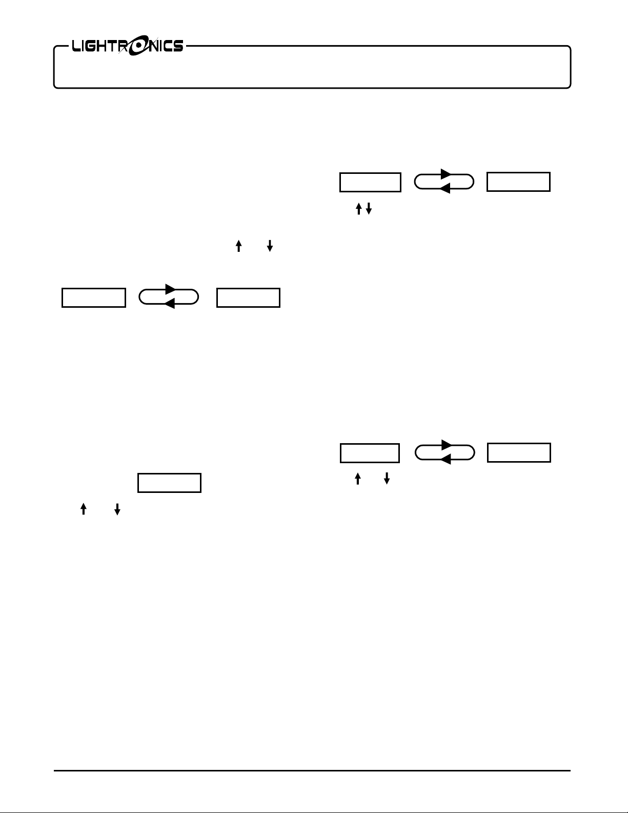
OPERATION
SETUP AND OPERATING CONFIGURATION
All operating functions and settings for the AB0602D are menu controlled using the LED Display
and the 4 buttons located below it on the control
circuit board.
DMX VALID
PACA
FACTORY DEFAULT CONFIGURATION
MENU
NEXT
SELECT
The AB-0602D is supplied with a factory default
setup configuration. The unit may be reset to this
condition by keeping the SELECT button held
down while power is applied. The display briefly
shows
FACt
while the reset is being performed.
The AB-0602D is set as follows when a reset is
performed:
1. The DMX pack address (
DMX address 1 (
P001
PACA
).
) will be set to
2. Softpatch is set to DMX addresses 1 - 6
3. Dropout trip points are set to 35 (14%).
4. All channels curves are set to
5. The architectural ID
DISPLAY STATUS INDICATORS
(ArCU)
LED1
is set to
.
00.
The LED display shows a dot near the upper left
corner when a valid DMX signal is being received.
MENU ACCESS AND USE
Hold the MENU/NEXT button down for aprox. 5
seconds to gain access to the complete menu system.
If there is no button activity for 1 minute while
inside the menus then the unit will revert back to the
normal display (
PACA
).
To exit from anywhere in the menus - Hold down
MENU/NEXT for aprox. 5 seconds. The unit will
revert back to the normal display (
PACA
).
A menu/display operation flow diagram is provided
at the back of this manual.
www.lightronics.com
Lightronics Inc. 509 Central Drive Virginia Beach, Va 234354 757 486 3588
Page 5
A
A
Page 5 of 10
AB0602D ARCHITECTURAL BALLAST DRIVER
Version 0.10 OWNERS MANUAL 06/25/2012
QUICK DMX ADDRESSING
The AB-0602D has a quick DMX address setup
which enables you to set the starting address of the
pack (the address for channel "A") without accessing
the rest of the menu system. When used, the
remaining 5 channels are set to the next consecutive
addresses.
During normal operation the LED display toggles
back and forth between
pack address such as
PACA
P001
and the current
.
Use the and
buttons to set different pack address. Push
SELECT to save the setting when done.
PACA P001
If you set the pack address to
P000
then the unit
will run in soft patch mode. In this mode you can set
ANY channel of the unit (A - F) to ANY DMX
address (000-512) by using the dimmer setup
(
dSEt)
menus. See
CHANNEL ADDRESSING
for
details.
CHANNEL TEST / LOCAL OPERATION
You can test the operation of each dimmer channel
by pushing MENU/NEXT. The display will show
the intensity of channel A (00 - 99%) shown below.
-00
Use and to adjust the intensity to the desired
level. Push MENU/NEXT to advance to the next
channel (Channel B). The dimmer will return to its
normal display when you go past the last channel.
The channel levels will remain when you set them.
The control console can turn off the circuits by
raising the channel fader to full then back down. A
useful feature of the channel test mode is that the
display shows the current intensity level of the
channel regardless of the control signal source.
CHANNEL ADDRESSING (SOFTPATCHING)
In order to invoke the softpatching settings you must
first set the pack address (
PACA
) to
P000
.
You can set the channel DMX softpatch addresses at
any time but they will be ignored if
at
P000
.
PACA
is not
TO SET CHANNEL SOFTPATCH ADDRESSES
Push SELECT at the
will toggle between the
dSEt
dA-A
menu. The display
and the current
DMX address assignment number.
dA-
001
Use to set the desired DMX address (000 - 512)
for the channel. Push SELECT to save the change.
Push MENU/NEXT to advance to the next channel
or hold down MENU/NEXT for aprox. 5 seconds
to exit from the menus
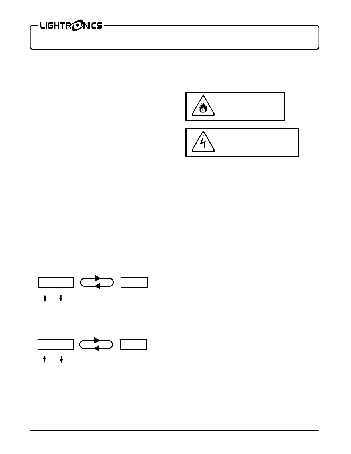
CHANNEL DROPOUT POINT
Many fixtures cannot operate reliably at very low
levels of intensity. The AB-0600D can cut off a
circuit when a low level threshold is reached to
prevent flickering and other undesired effects. The
dropout point can be set for each of the 6 circuits.
Push SELECT at the
dSEt
menu. Then push
MENU/NEXT until the display toggles between
dd-A
and the current dropout value setting. The
range is from 5 to 255. 5 is the lowest.
dd-A
035
Use and to set the desired value for that
channel. Push SELECT to save the change.
Push MENU/NEXT to advance to the next channel
or hold down MENU/NEXT for aprox. 5 seconds
to exit from the menus.
RESPONSE CURVE SELECTION
Each AB-0602D channel has a selection of response
curves to match a variety of lamp and fixture types:
DIM:
(dlnn) Used for incandescent lamps.
LINEAR:
LED1:
FLUORESCENT:
(Llnr) Used for some CFL fixtures..
(Led1)
Used for many LED
fixtures.
(FLUO) For dimmable
fluorescent ballasts
The menu used to select curves includes 4 additional
items which are not currently supported. They are
LED2, LED3, CUR6, and CUR7
.
They can be selected but will be ignored.
www.lightronics.com
Lightronics Inc. 509 Central Drive Virginia Beach, Va 234354 757 486 3588
Page 6

Page 6 of 10
AB0602D ARCHITECTURAL BALLAST DRIVER
Version 0.10 OWNERS MANUAL 06/25/2012
Push SELECT at the
dSEt
menu. Then push
MENU/NEXT until the display toggles between
dC-A
and the current curve setting.
dC-A
Dinn
Use to set the desired curve for that channel.
Push SELECT to save the change.
Push MENU/NEXT to move to another channel.
WALL STATION REMOTE CONTROL
The AB-0602D can be controlled using Lightronics
architectural smart remote wall stations. This is
done using a NON-DMX wiring bus to connect the
units. Multiple AB-0602D's and/or multiple smart
remote wall stations may be connected together.
The AB-0602D can store 64 preset scenes which can
be activated by the smart remotes. These scenes are
grouped according to which type of smart remote
can use them. Scenes 1 - 32 are reserved for push
button and IR remotes. Scenes 51 - 63 are used with
fader remotes. Both push button and fader remotes
may be connected to the same remote bus. If
multiple AB-0602D units are connected to a remote
then each one will activate its own stored scene.
BUTTON AND IR SMART REMOTES
These remotes activate individual scenes which have
been stored in the AB-0602D. Scenes will activate
on an "exclusive" basis (only one scene may be on at
a time). Currently available button remotes are the
AC-xx, AK-xx, and AI-1001.
These units are set to control scenes starting at scene
number one. It is possible to order a remote to use
other scenes.
The scene activation buttons will toggle. In other
words a scene will go OFF if you push its button
while the scene is active.
The OFF button invokes a system wide
BLACKOUT. (all scenes will be turned off
regardless of their source).
FADER SMART REMOTES
These units use specific individual scenes which
have been stored in the AB-0602D on a "pile on"
basis. In other words multiple scenes will merge
together in a "greatest of " fashion. This means that
the intensity of any given channel will go to the
highest level of all the scenes which use it.
Currently available fader remotes are the AF-2104,
AF-3107 and AF-5113.
All fader remotes will interact with scenes beginning
at scene 51. This refers to the lowest numbered
fader on the remote. The other faders on that remote
will use the next consecutively numbered scenes (52,
53, 54, etc.).
UNIT ID ADDRESS ASSIGNMENT
The smart remote connection bus used with AB0602D's must have a single controlling (master) unit
on it. Assigning the master unit on the bus is
accomplished by setting unit ID addresses.
When using only one AB-0602D with smart remotes
control, the unit must be set to UNIT ADDRESS 00.
If multiple AB-0602D's are used then one of them
(and ONLY one of them) must be set to UNIT
ADDRESS 00. The remaining units may be set to
any other unit address. It is recommended that they
be set to consecutive numbers starting at 01.
TO SET THE UNIT ID ADDRESS
Hold MENU/NEXT for aprox. 5 seconds to access
the menus. The display will show
dSET
.
Push MENU/NEXT until the display shows
SYSt
.
Push SELECT.
Push MENU/NEXT until the display toggles
between
ArcU
ArcU 00
and the current unit address.
Use and to change the unit address number.
Then push SELECT to save the selection.
Hold MENU/NEXT for aprox. 5 seconds to exit
from the menus.
www.lightronics.com
Lightronics Inc. 509 Central Drive Virginia Beach, Va 234354 757 486 3588
Page 7
Page 7 of 10
AB0602D ARCHITECTURAL BALLAST DRIVER
Version 0.10 OWNERS MANUAL 06/25/2012
CREATING AND SAVING SCENES
Scenes to be activated by an AB-0602D must first be
created and stored (recorded) in the unit. Scene
recording stores the current intensity levels of all six
channels in the unit regardless of how they were set.
Intensity levels for a scene can be set using only the
dimmer or by operating the unit with a DMX
console. Each scene created has an associated user
settable fade time.
A universal BLACKOUT scene (all channels OFF)
is also available. It appears as scene number 00 in
the menus. The blackout scene has a user settable
fade time.
TO RECORD A SCENE
Set the intensity for each channel in the unit to the
desired brightness.
Hold MENU/NEXT for aprox. 5 seconds to access
the menus. The display will show
dSET
.
Push MENU/NEXT until the display shows
SYSt
between
. Push SELECT. The display will toggle
CnFG
and the currently selected control
source.
Push MENU/NEXT until the display toggles
between
ScEn
ScEn
and the 00 (scene 00).
00
Use and to change the scene number. Then
push SELECT to record the intensity levels.
The menu will advance to allow you to set the fade
time for that scene. The display will toggle between
FAdE and the current fade time (seconds).
FAdE
00
Use and to change the time. Then push
SELECT to save the setting.
The display will revert to the scene number selection
menu. If you are operating with a DMX console you
can change the channel levels and record to another
scene. If operating in local mode you will have to
exit from the menus to set new channel intensities.
Hold MENU/NEXT for aprox. 5 seconds to exit
from the menus.
MAINTENANCE AND REPAIR
DANGER
RISK OF FIRE
RISK OF ELECTRIC SHOCK
DANGER
FUSE REPLACEMENT
REMOVE ALL POWER TO THE UNIT BEFORE
REPLACING THE FUSE
The only user serviceable part is a 1 1/4" X 1/4"
fuse. Replace the fuse ONLY with a 1/2 Amp,
250VAC, fast blow fuse. The diagram
DIMENSIONS AND LOCATIONS
shows the fuse
location.
INTERNAL SERVICE
Internal service on the unit by other than Lightronics
authorized agents will void the warranty.
If service is required, contact the dealer from whom
you purchased the dimmer, or Lightronics Service
Department, 509 Central Drive, Virginia Beach,
VA 23454. Tel: 757 486 3588.
www.lightronics.com
Lightronics Inc. 509 Central Drive Virginia Beach, Va 234354 757 486 3588
Page 8

Page 8 of 10
AB0602D ARCHITECTURAL BALLAST DRIVER
Version 0.10 OWNERS MANUAL 06/25/2012
MENU / DISPLAY OPERATION
www.lightronics.com
Lightronics Inc. 509 Central Drive Virginia Beach, Va 234354 757 486 3588
Page 9
Page 9 of 10
AB0602D ARCHITECTURAL BALLAST DRIVER
Version 0.10 OWNERS MANUAL 06/25/2012
DIMENSIONS AND LOCATIONS
www.lightronics.com
Lightronics Inc. 509 Central Drive Virginia Beach, Va 234354 757 486 3588
Page 10

Y
All Lightronics products are warranted for a period of TWO/FIVE YEARS from the date of
purchase against defects in materials and workmanship.
This warranty is subject to the following restrictions and conditions:
A) If service is required, you may be asked to provide proof of purchase from an authorized
Lightronics dealer.
B) The FIVE YEAR WARRANTY is only valid if the warranty card is returned to Lightronics
accompanied with a copy of the original receipt of purchase within 30 DAYS of the purchase
date, if not then the TWO YEAR WARRANTY applies. Warranty is valid only for the
original purchaser of the unit.
C) This warranty does not apply to damage resulting from abuse, misuse, accidents, shipping,
and repairs or modifications by anyone other than an authorized Lightronics service
representative.
D) This warranty is void if the serial number is removed, altered or defaced.
E) This warranty does not cover loss or damage, direct or indirect arising from the use or
inability to use this product.
F) Lightronics reserves the right to make any changes, modifications, or updates as deemed
appropriate by Lightronics to products returned for service. Such changes may be made
without prior notification to the user and without incurring any responsibility or liability for
modifications or changes to equipment previously supplied. Lightronics is not responsible
for supplying new equipment in accordance with any earlier specifications.
G) This warranty is the only warranty either expressed, implied, or statutory, upon which the
equipment is purchased. No representatives, dealers or any of their agents are authorized
to make any warranties, guarantees, or representations other than expressly stated herein.
H) This warranty does not cover the cost of shipping products to or from Lightronics for
service.
I) Lightronics Inc. reserves the right to make changes as deemed necessary to this warranty
without prior notification.
Lightronics Inc. 509 Central Drive Virginia Beach, VA 23454 20050125
WARRANT
 Loading...