

Page 1

EPP 35” Magnum
EPP 35” Rebel Z
Instruction Manual
Page 2
Hardware
Carbon
6mm x 1mm x 1000mm strip
(3)
3mm x 1mm x 500mm strip (1)
2mm x 1000mm rod (1)
1mm x 1000mm rod (2)
Poly Fiber Control Horn Card
Motor Mount Screws
Motor Mount Tubing
Adhesive Lined Heat Shrink
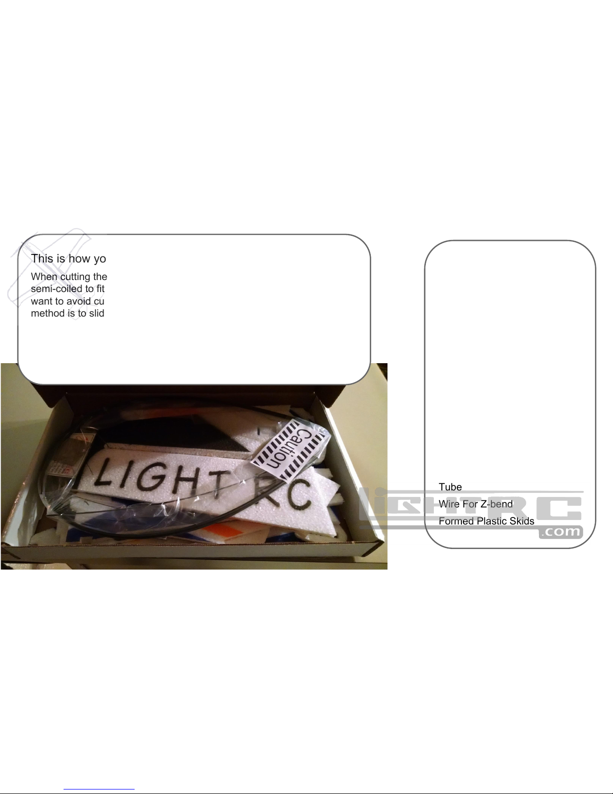
Tube
Wire For Z-bend
Formed Plastic Skids
This is how your kit will arrive
When cutting the hardware package open use caution. The contents are
semi-coiled to fit in the box. They will spring open very quickly. You also
want to avoid cutting or losing any of the parts in the bag. Safest
method is to slide the carbon out one at a time, leaving the bag coiled.
All kits come with motor mount tube and screws. A poly-card with the
needed control horns (and other poly parts if needed) Heat shrink tube
(self adhering) for control horns (do not use CA with this). Wire for zbends is also included. Ohh, and lots of carbon fiber.
Page 3

Carbon Lengths
1mm rod lengths
(see pics later in manual)
(x4) 5.5"
4.75"
4.5"
4.0"
3.0"
Wing Main spar 6mm flat, 30.5"
Sub spar 3mm flat, 29.25"
Gear legs 9.0"
Tail skid 6mm flat, 6.5"
Aileron braces 2mm rod 3.5"
Build Order
(if you don’t want to follow the manual)
Wing -> Nose -> Wing
Main Spar 6mm
Sub Spar 3mm
Elevator Spar 3mm
Aileron Spars 2mm
Reinforce Hinges
Horizontal Mid -> Wings
Horizontal Tail -> Wings
Vertical top nose -> Vertical Tail
Test fit elevator servo ( then glue)
Vertical lower -> Wings
Gear Legs 6mm
Truss Work 1mm
Tail Skid 3mm
Wheel Pants
Skids
Vertical Upper
Vertical Support Truss 1mm
Page 4
Suggested Setup
Electronics
Motor
Cobra 2208-34
Esc
Castle Creations Talon 15a
Servos
(4) Futaba s3114
Battery
500-800mAh 3s
Throw
Ailerons ±40°
Elevator ±50°
Rudder ±40°
Expo
Ailerons 30%
Elevator 35%
Rudder 35%
CG
8” From Nose of Plane (Foam)
Page 5

Hardware
Carbon
6mm x 1mm x 1000mm strip
(2)
3mm x 1mm x 1000mm strip
(1)
2mm x 1000mm rod (1)
1mm x 1000mm rod (2)
Poly Fiber Control Horn Card
Motor Mount Screws
Motor Mount Tubing
Adhesive Lined Heat Shrink
Tube
Wire For Z-bend
Formed Plastic Skids
This is how your kit will arrive
When cutting the hardware package open use caution. The contents are
semi-coiled to fit in the box. They will spring open very quickly. You also
want to avoid cutting or losing any of the parts in the bag. Safest
method is to slide the carbon out one at a time, leaving the bag coiled.
All kits come with motor mount tube and screws. A poly-card with the
needed control horns (and other poly parts if needed) Heat shrink tube
(self adhering) for control horns (do not use CA with this). Wire for zbends is also included. Ohh, and lots of carbon fiber.
Page 6
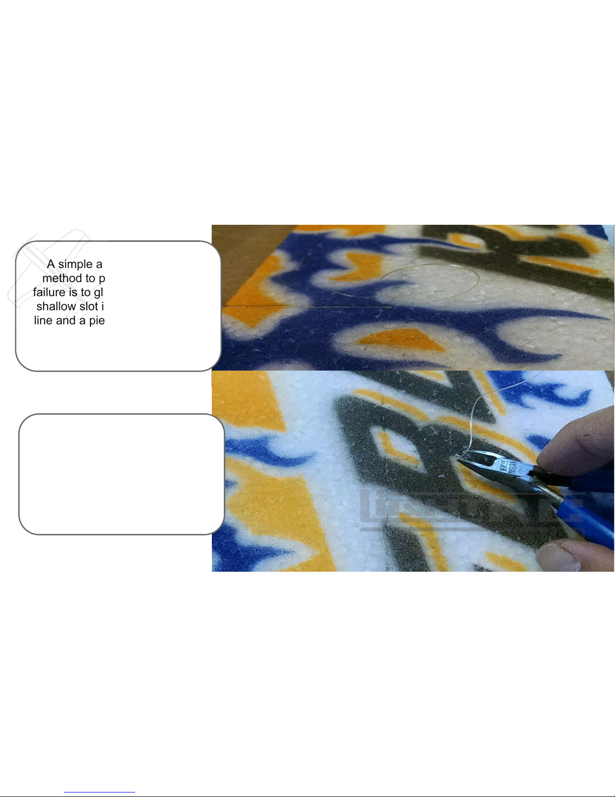
A simple and very effective
method to prevent epp hinge
failure is to glue in fishing line. A
shallow slot is cut across hinge
line and a piece of fishing line is
inserted. Do this at both ends of
the hinge and at control horn.
It is possible to use many other
filaments. Various threads work
well, nylon, kevlar, etc. If using CA
be careful to avoid the glue
wicking into the pivot. Filament
packing tape also works very well
Page 7

The rectangular recess pockets are for
mounting servos. The servo arm should
pass through the corresponding slots.
This arrangement is to provide better
linkage geometry than previous designs.
Notches will help line up parts. Most
builders have a glue preference. Many
glues will work well for this.
Horizontal nose, midsection, wing panels
and elevator assemblies can all be glued
up with parts laying flat on build table.
Only thing to watch for is to not fill carbon
slots with glue.
Page 8

Glue the Vertical Fuselage parts
together as shown.
Glue the Elevator
Carbon Strip 3mm
11⅝” into place
Glue the Aileron
counterbalance
braces (3½) in each
wingtip
Page 9

Carbon can now be added
to horizontal assembly.
Wing carbons are 6mm x
1mm. Front wing carbon is
35 5/16”. Rear wing carbon
is 31 ½”. Test fit the carbon
after cutting to length, then
glue.
Aileron counterbalance
carbons are 2mm rod x 3 ½”
long. Elevator carbon is
3mm x 1mm x 15”.
Weighting the assembly to
hold assembly flat while all
glue dries can help insure a
flat build.
Page 10

Glue lower side of vertical fuselage to bottom. Foam can be slightly stretched and
compressed to fit into notches. Glue a small area at a time while checking for square with
square scrap foam supplied with kit.
Be sure the assembly lies flat and does not lift off the table anywhere. If it does not lay flat,
move the lower until it will lay flat before gluing.
Page 11

Carbon can now be added for landing gear legs, (2) 6mm x 1 mm x 9” long. A notch is
provided in front of wing and a slot is precut for intersecting point in vertical fuselage. These
are glued into place at notches and intersecting point being sure to pull carbon up away
from table to top of slot.
9
Page 12

5 ½
4 ¾
5½
5½
Start by threading carbon through center of vertical fuselage and
then into wing. After getting location established, pull out and add
drop of hot glue to each end of carbon. Reinsert while twisting the
carbon truss. This will drag glue down into hole with carbon and
makes for a strong and clean install.
5½
4
Page 13

Install the formed
plastic parts. Cut
the formed plastic
into sections that
fit onto the bottom
of the wheel
section of the
wheel pant foam.
Cut a slit into the
gear leg support.
Glue a length of
1mm rod into the
slit.
The 1mm rods that
meet at the gear
leg intersection
should touch the
gear legs. This will
help strengthen by
reducing the force
the foam absorbs.
Glue the reinforced
gear leg supports
into the plane.
Create a little
preload by holding
the foam into the
carbon enough to
slightly flex it.
Page 14

Top side of fuselage can now be installed. Same way as bottom being careful to fit snug
into slots and squaring with horizontal while gluing. Back will wrap around elevator and
meet up with underside.
Page 15

6½4½
The back of the upper fuselage will
wrap around elevator and meet up
with underside. This intersection is
where to install the tail skid, 3mm x
1mm x 7”.
Carbon braces can now be added to top side of plane to
support and hold rudder square to the elevator. Run
1mm carbon rod from top of rudder assembly to where
bottom carbon meets the elevator. It is acceptable to use
carbon on only one side of the vertical stab.
3
Page 16

Prepare for electronics by cutting the z-
bend wire into (8) equal lengths. Also
cut the poly mount tubing into (4) equal
lengths.
Now plane can be turned over on the
workbench to check for level. Gear legs
can be shortened until the wing is
parallel with work surface.
Page 17

After the gluing on
the mount tubes,
trim the tubes.
Clipping the tubes
about 1/16th
behind the motor
mount foam. This
will allow for thrust
angle changes.
To mount the motor, start by mounting the poly tubing to the motor, or to
the X-mount without the motor.
Before gluing the tubing to the plane, spread a thin layer of glue around
that area that the tubes will glue to. Tubing should be glued to sides of
plane as shown. This arrangement puts the torque of motor pushing
against surface and not pulling away from the foam. While the glue is
setting twist the motor against the plane. This will self center the motor
on the nose of the plane.
Page 18

The supplied heat
shrink is adhesive
lined. Do NOT use
CA with this heat
shrink. Simply
position and heat.
If needed the tube
can be reheated to
reposition.
To create linkages
with minimal slop,
rotate the z-bend
around the control
rod. The intent is
to put the heat
shrink against the
control horn.
Control horns are included on
the polyfiber hardware card.
Be sure to use the horn with
notch for the elevator. The
notch fits over the carbon
stiffener. 2mm Carbon can be
cut to length for push rods.
Reheat the heat shrink as
needed to center surfaces.
Page 19

Suggested Setup
Electronics
Motor
Cobra 2208-34
Esc
Castle Creations Talon 15a
Servos
(4) Futaba s3114
Battery
500-800mAh 3s
Throw
Ailerons ±40°
Elevator ±50°
Rudder ±40°
Expo
Ailerons 30%
Elevator 35%
Rudder 35%
CG
8” From Nose of Plane (Foam)
 Loading...