

Page 1
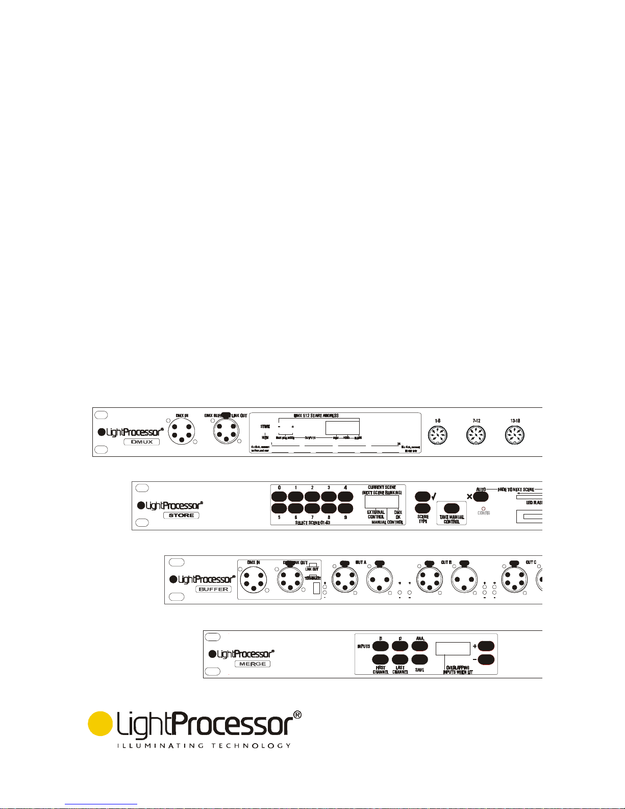
DMX TOOLS
- DMuX
- Store
- Buffer
(Rack- and Truss-Mounting)
- Merge
INSTALLATION AND OPERATING MANUAL
Page 2

Thank you for buying a LightProcessor product. To obtain the best results, please read this
instruction manual carefully.
Nous vous remercions d’avoir acheté un produit LightProcessor. Pour obtenir les meilleurs résultats,
nous vous prions de bien vouloir lire attentivement ce manuel.
Wir bedanken uns für die Wahl eines LightProcessor-Produktes. Für eine reibungslose Bedienung
lesen Sie sorgfältig dieses Handbuch.
Le damos las gracias que Ud. ha comprado un producto de LightProcessor. Para los mejores
resultados lea cuidadosamente este manual.
Please be aware of the following warning notices and their meaning!
Veuillez faire attention aux avertissements suivants!
Beachten Sie bitte die folgenden Warnungen !
Dese cuenta de los siguientes avisos importantes!
CAUTION! RISK OF ELECTRIC SHOCK
ATTENTION! RISQUE DE CHOC ELECTRIQUE
ACHTUNG! GEFAHR EINES STROMSCHLAGES
¡ATENCION! PELIGRO DE SHOCK ELECTRICO
CAUTION! REFER TO INSTRUCTION MANUAL
ATTENTION! REFEREZ-VOUS AU MODE D'EMPLOI
ACHTUNG! BEACHTEN SIE BITTE DIE BEDIENUNGSANLEITUNG
¡ATENCION! REFERIRSE AL MANUAL DE INSTRUCCIONES
IT IS ESSENTIAL THAT YOU MAKE AN EARTH CONNECTION BEFORE
CONNECTING THE EQUIPMENT TO THE MAINS SUPPLY .
IL EST INDISPENSABLE DE RACCORDER L'APPAREIL A LA TERRE AVANT
D'ETABLIR LA CONNECTION AU SECTEUR.
VOR ANSCHLUSS DES APPARATS BITTE UNBEDINGT EINE ERDUNG
DURCHFÜHREN.
ALTA VOLTAJE. NECESITA ABSOLUTAMENTE UNA CONEXION CON TIERRA
ANTES DE HACER LA CONEXION A LA RED.
The material contained in this document is for information purposes only and is subject to change without notice. LightProcessor Limited assumes no
responsibility for any errors or omissions that may appear in this manual.
Le contenu de cette documentation n’est donné qu’à titre indicatif et peut changer sans avis préalable. LightProcessor Limited n’accepte pas de
responsabilité pour n’importe quelle erreur ni omission.
Die Informationen in diesem Handbuch sind unverbindlich gegeben und wir behalten uns das Rech vor, Änderungen zu machen. LightProcessor Limited
akzetptiert für Fehler und Auslassungen keine Verantwortlichkeit.
El contenido de este documento es dado para su información solamente y está sujeto a cambios sin previo aviso. LightProcessor Limited aceptan
ninguna responsabilidad para errores y omisiones.
Page 3

Page
DMuX 3
Store 5
Buffers 13
Merge 15
Instruction Manual - all products
CONTENTS
ACCESSORIES PACKED WITH THE PRODUCT
Page 4

Read the instructions in this handbook carefully, as they give important information regarding safety during installation
and use.
Be sure to keep this manual with the product for ease of future reference. If the product is sold or given to another
operator, make certain that they also receive the manual.
•This product is not intended for home use.
•After removing the packaging, check that the product is not damaged in any way. If in doubt, do not use it.
Contact an authorised LightProcessor distributor.
•Packaging material (plastic bags, foam, nails etc. ) must not be left within the reach of children, as it can be
dangerous.
•The product must only be operated by adults. Do not allow children to tamper or play with it.
•The electrical work necessary for installing the product must be carried out by a qualified electrician.
NEVER USE THE PRODUCT UNDER THE FOLLOWING CONDITIONS:-
•In places subject to excessive humidity
•In places subject to vibrations or bumps
•In places with an ambient temperature in excess of 30°C or less than 0°C
•Protect the product from excessive dryness or humidity (ideal conditions are between 35% and 80%)
•Do not dismantle or modify the product
•Ensure that no liquids or metal objects enter the product
•Should any liquid be spilled on the product, disconnect the power supply immediately
•In the event of serious operating problems stop using the product immediately and either contact the nearest
LightProcessor distributor for assistance or contact the manufacturer directly
•Never try to repair the product yourself. Repairs by unqualified people could cause damage or faulty
operation. Contact your nearest LightProcessor dealer
•When carrying out any work, always comply (particularly regarding safety) with all regulations in force in the
country in which the product is being used
ALWAYS INSIST ON ORIGINAL SPARE PARTS BEING FITTED
LightProcessor DMXTools, version 2, April 2003
Page 1
GENERAL INSTRUCTIONS
Page 5

1. Unpack the Product. (Ensure you do not throw away any accessories packed separately in the box.)
2. Mount the product in a 19 inch rack; it requires 1U of space. In the case of the Buffer secure it to the rig using
a hook clamp and safety chain.
3. Connect control cables.
4. Make an earthed mains connection.
LightProcessor DMXTools, April 2003
Page 2
QUICK SET-UP AND INSTALL
Page 6
The DMuX is a 24 channel demultiplexer which decodes DMX512 (1990 or earlier) signals and converts them
into 0 to +10V analogue signals. A negative output model is available on special order
POWER CONNECTION
The DMuX requires no external power transformer and should be connected directly to a mains voltage as
indicated on the unit's rear panel.
Applying mains to the DMuX in the absence of a DMX input signal will produce a fault condition, indicated by
'Flt' in the display.
DMX CONNECTION
Buffered DMX input and through connection to the DMuX may be made using either the 5-pin XLR on the
front panel or the 3-pin XLR on the rear panel, as you choose. In all cases XLR's should be wired according
to the USITT standard:- pin 1 screen, pin 2 data negative, pin 3 data positive. Pins 4 and 5 on the 5-pin XLR
are not used.
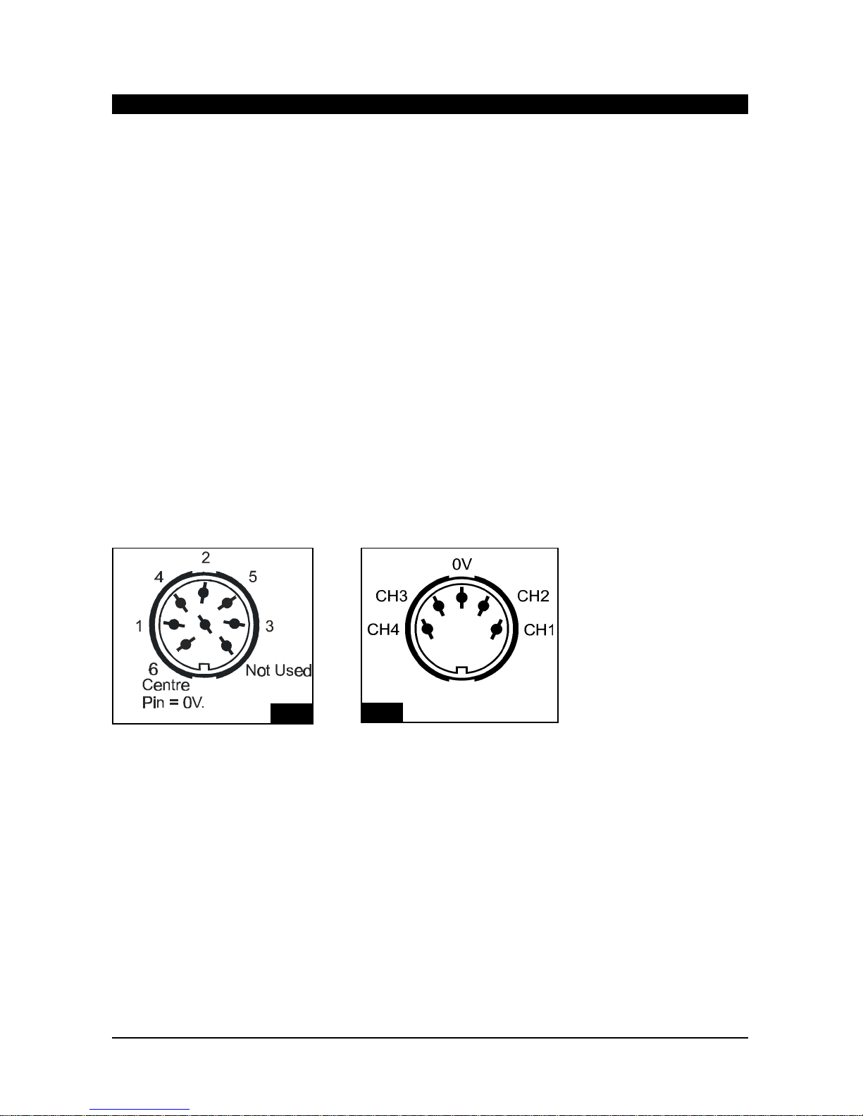
ANALOGUE CONNECTION
Analogue output channels are as shown below. Whether you use the four 8-pin DIN's on the front or the rear
panel, as shown in Fig. 1, or the six 5-pin DIN's on the rear, as shown in Fig. 2 is again a matter of choice.
The analogue output voltage is 0 to +10V. 0 to -10V units are available to special order. Connectors are
labelled to indicate which channels of the 24 they refer to.
SETTING THE DMX START ADDRESS
The DMuX requires one start address which refers to a group of 24 consecutive DMX channels.
Use the buttons '+' and '-' to select the desired start address, then press 'STORE'. The letters 'ADD' will
appear in the display to indicate that the address has been stored.
OUTPUT FROM THE DMuX
Output is indicated in the monitor LEDs.
DMuX
LightProcessor DMXTools, April 2003
Page 3
Fig. 1
Fig. 2
Page 7
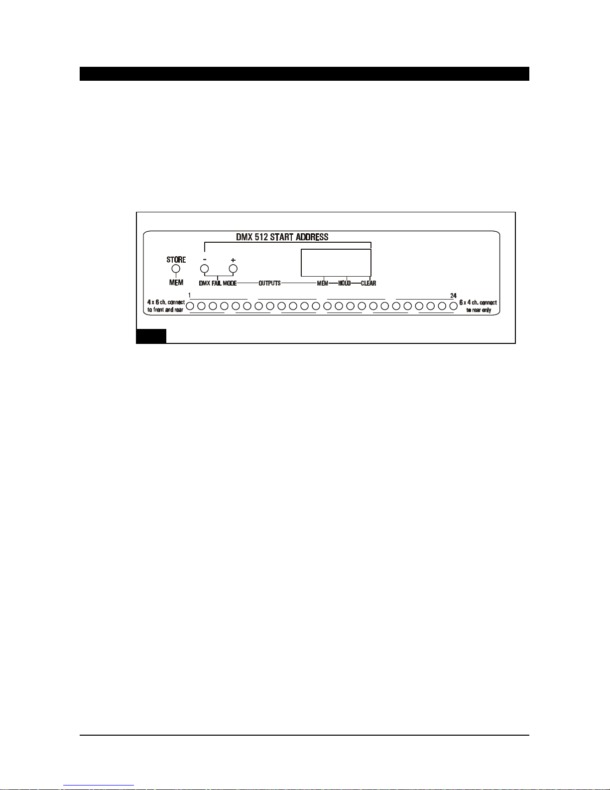
DMX FAIL MODES
When no DMX signal is received by the DMuX or some other fault condition exists, the letters 'Flt' will appear
in the display.
You may pre-program one of the following options as a response, in case such a fault condition should occur.
See Fig. 3:-
MEM A pre-programmed scene is output.
HOLD The last instruction received is held in the outputs.
CLR Nothing is output.
The current mode is indicated by a dot in the bottom of one of the sections of the display. The mode is
changed by holding down both the + and - buttons together; the dot then scrolls between the sections. When
the dot appears in the appropriate section of the display, hold down STORE until SCE appears in the display.
The mode is now selected and remains in memory until cancelled by re-programming.
To store a scene using the MEM function, first output the scene from your desk or controller. Hold down the
+ and - buttons until the dot appears in the MEM section of the display. Hold down STORE until the letters
SCE appear in the display.
DMuX
LightProcessor DMXTools, April 2003
Page 4
Fig. 3
Page 8

GENERAL
The Store is designed to be rack mounted. The 5-pin XLR DMX connectors and the mains input are rear
panel mounted. There is also a 25-pin sub-D connector on the rear panel for optional remote control.
USES
The Store is suitable for use as a back-up to any DMX lighting controller, storing up to 64 scenes of all 512
DMX channels. Install it as the first device in the DMX chain after the controller.
Alternatively, it can be used as a stand-alone playback unit, once it has been loaded from a controller or
from a memory card.
OPERATING MODES
(a) Configuration Mode
(i) To set up global fade and hold times. These are the default times that will apply to any scene for which
no specific time is programmed.
(ii) To tell the Store what to do in the event of a loss of data.
(b) Pass Through Mode
When DMX signals are being received and neither manual nor remote control is active, the Store remains
passive and allows the DMX signal to pass down the chain to the next DMX device. Pass Through Mode is
indicated in the display by a dot showing 'DMX OK'.
(c) Scene Loading
Scenes are loaded into memory while the Store is in Pass Through mode.
(d) Manual Control
The Store may be controlled manually from the front panel, either switching to the next scene by means of
the AUTO button or fading to the next scene using the slider. During the fade the slider LED flashes to
indicate that a fade is in progress. Manual Control active is indicated in the display by a dot showing
'MANUAL CONTROL'
(e) External Control
Alternatively the Store may be remotely controlled by +10/12V signals. The sub-D connector, mounted on
the rear panel, is used for this purpose. Separate fade and hold times are assignable to individual scenes,
along with flags designating a scene as the first or last in a sequence. The sequence may be set to run
once or to loop. External Control active is indicated in the display by a dot showing 'EXTERNAL
CONTROL'.
SWITCHING ON
THESE INSTRUCTIONS ASSUME THAT THE STORE IS CONNECTED TO A SOURCE OF DMX AND
THAT IT IS RECEIVING A VALID SIGNAL. IF THE STORE IS NOT RECEIVING DMX, IT WILL ENTER
MANUAL MODE AND WILL NOT ALLOW CONFIGURATION OR PROGRAMMING.
If the slider has been left parked in an active position, the display will show SLI and the slider LED will
flash. Move the slider to its inactive zone, i.e. above 90% or below 10%.
When switched on for the first time the display will show a flashing ---. On subsequent occasions it will
show the number of the first valid scene.
Store
LightProcessor DMXTools, April 2003
Page 5
Page 9

CONFIGURATION
This mode allows the adjustment of (a) a global fade time, (b) the global hold time and (c) a loss of data
key. Press SCENE TYPE at any time to toggle between (a), (b) and (c). Press 6 to exit configuration
mode. See Fig. 4. The Store must be receiving DMX. To enter configuration mode, press the CONFIG
switch using a thin screwdriver or similar device. The display shows CnF.
GLOBAL FADE TIME
The display shows FAd, followed by the current global fade time expressed in seconds 0-99. Move the
slider to adjust the fade value between 0-0.9 seconds and 1-99 seconds, then press 4. The display then
shows YES, then the new global fade time.
GLOBAL HOLD TIME
Press 6 to exit configuration mode or SCENE TYPE to adjust the global hold time. The display shows Hld
and then the current hold time. Move the slider to adjust the hold value between 0-0.9 seconds, 1-59
seconds and 1-30 minutes, then press 4. The display then shows YES, then the new global hold time.
To avoid confusion when setting fade and hold times note the position of the dot in the display, as follows:-
00.1 = one tenth second.
01.0 = one second
1. = one minute
LOSS OF DATA KEY
Press 6 to exit configuration mode or SCENE TYPE to adjust the loss of data code. The display shows
Lod. There are four loss of data keys available. For stand-alone use select Lod 3; for backup use choose
Lod 0,1 or 2.
0 = Blackout. Display shows --- on loss of data.
1 = Hold last valid signal received. Display shows --- on loss of data.
2 = Go to and hold scene 00. Display flashes 00 on loss of data.
3 = Hold the currently selected scene. Display shows scene number on loss of data.
Use the slider to adjust these values, then press 4. The display shows YES, then the new value.
Press SCENE TYPE to return to fade time adjustment or 6 to exit configuration mode.
Store
LightProcessor DMXTools, April 2003
Page 6
Move Slider
Move Slider
Move Slider
Press
CONFIG
Display showsFad
(0-99secs.)
Press
Press
Press
Display shows Hld
(0-30mins.)
Display shows Lod
(0-3)
Press SCENE TYPE
Press SCENE TYPE
Press SCENE TYPE
4
4
4
=
Exit CONFIG
6
=
Exit CONFIG
6
=
Exit CONFIG
6
=
Abort
6
=
Abort
6
=
Abort
6
Fig. 4
Page 10

LOADING SCENES INTO THE STORE
Ensure that the Store is in Pass Through mode, i.e. release manual and/or external control.
Output the desired scene from any DMX desk or controller.
Give the scene a number between 00 and 63 using the numeric buttons.
Hold the 4 button pressed. The display first shows Scn and then YES.
Release the 4 button. The scene is now stored under the number you chose.
A number of attributes are stored with each scene. These are explained under the section, SCENE
TYPES.
THE DEFAULT SCENE
As described in the section CONFIGURATION, it is possible to program the Store to go to a default scene
when no DMX signal is received. This is scene 00. It may be loaded into memory in Pass Through mode
just like any other scene. It may be selected in Pass Through mode and then output in Manual Mode or
External Mode but it may not be accessed when in Manual Mode or External Mode.
SELECTING A SCENE
Use the numeric buttons to select a scene between 00 and 63. The number of the selected scene is shown
in the display.
If you are in Pass Through mode, the chosen scene will be output when you go to Manual Control. If you
are in Manual Control, the chosen scene will be the next scene to be output after pressing the AUTO
button or using the slider. In External Control the chosen scene will be the next scene to be output after
the use of the STEP command.
SCENE TYPES
When you set up a scene (see the section LOADING SCENES INTO THE STORE), it is given default fade
and hold times according to the selections made during configuration.
While in Pass Through Mode use the SCENE TYPE button :To change or edit fade and hold times.
To reset the scene back to default values.
To delete it.
To flag it as the first scene in a sequence.
To flag it as the last scene in a sequence.
Each press of the button will step you through the following list. Install the TYPE as indicated in the table
Abort any option by waiting for a time-out after five seconds or by pressing 4.
FADE values are adjustable between 0-0.9 seconds and 1-99 seconds. HOLD is adjustable between 0-0.9
seconds, 1-59 seconds and 1-30 minutes.
The following table shows the available scene types.
Store
LightProcessor DMXTools, April 2003
Page 7
Page 11

Store
PASS THROUGH MODE
Pass Through mode active is indicated by a dot in the righthand element of the display, labelled
DMX OK.
Valid DMX is being received and the Store is inactive.
MANUAL CONTROL
Manual control active is indicated by a dot in the centre element of the display.
If the DMX signal fails, the Store automatically enters MANUAL MODE and acts according to the
LOSS OF DATA key programmed during configuration.
Alternatively, you may enter MANUAL CONTROL mode by pressing the TAKE CONTROL button.
The Store then outputs the scene shown in the display until it receives a further command.
MOVING BETWEEN SCENES WITH THE AUTO BUTTON
If the AUTO button is pressed, the Store steps to the next valid scene. If any other scene is
selected, the display will flash alternately the number of the current scene and the number of the
next-selected scene. Press AUTO to step to the next-selected scene.
Any programmed fade time is processed; hold times are ignored. When the last programmed
scene or scene 63 is accessed, the next step will be to scene 1.
MOVING BETWEEN SCENES WITH THE SLIDER
Move the slider and the Store fades from the current scene to the next valid scene at the speed
that you move the slider. The display flashes alternately the number of the current scene and the
next scene. The slider LED flashes to show that a fade is in progress when it is between 10% and
90% of its travel.
You may elect to fade to any valid scene. Enter the number of the scene to which you want to
fade. The display flashes alternately the number of the current scene and the desired scene.
During the fade the slider flashes to show that it is active.
Pre-programmed fade and hold times are ignored. When the last programmed scene or scene 63
is accessed, the next fade will be to scene 1.
LightProcessor DMXTools, April 2003 Page 8
TYPE FUNCTION
TO INSTALL TYPE
rST
FAd
Hld
dEL
SoC
End
Sets default values
Set FADE on and allow
adjustment.
Set HOLD on and allow
adjustment.
Delete scene
Start of chase sequence Last
scene in chase sequence
Press STORE until display shows YES
Press STORE. Current FADE value is shown in
display.
Adjust value using slider. Press 4 until display
shows YES to save.
Press 4. Current HOLD value is shown in display.
Adjust value using slider. Press 4 until display
shows YES to save.
Press 4 until display shows YES
Press 4 until display shows YES
Press 4 until display shows YES
Page 12
CHASE SEQUENCES
When a scene of the type SoC is encountered, a chase starts to run according to pre-programmed fade
and hold times. It ignores any deleted or empty scenes and continues until it encounters a scene of the
type End: it then loops back to the SoC scene. To stop a chase and pass to the next scene outside the
loop, use the slider or press AUTO. During a chase the display shows only the number of the first scene in
the chase. The slider LED flashes slowly to indicate that a chase is running.
RETURN TO PASS THROUGH MODE
Press TAKE MANUAL CONTROL to return to PASS THROUGH MODE, so long as DMX is being received
(a dot is showing in the right hand element of the display).
If DMX is not being received, the Store remains in MANUAL MODE.
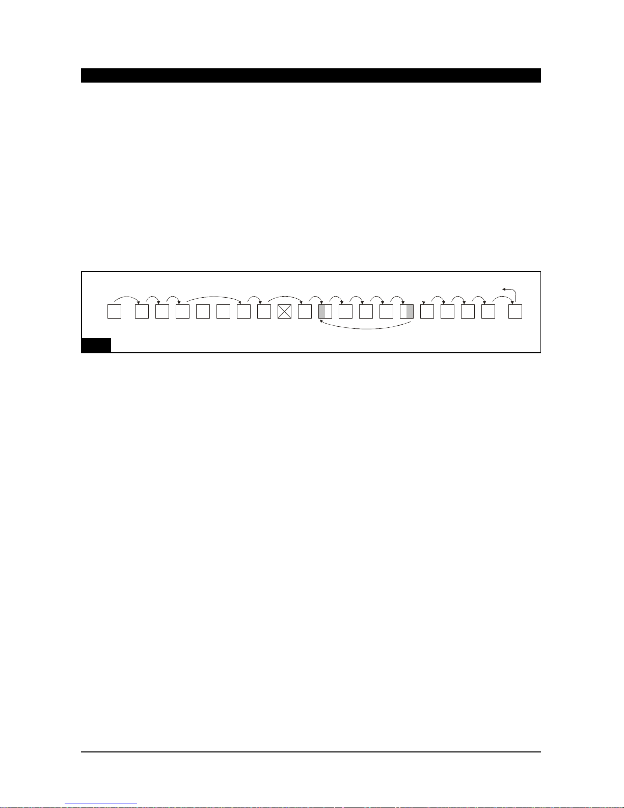
MANUAL CONTROL - EXAMPLE
(x) The DMX input fails. The unit outputs scene 00 and switches to manual control.
(a) The first press of the AUTO button advances the Store to scene 1.
(b) Either -
Subsequent presses of AUTO advance you to scenes 2 and 3. FADE times are actioned but HOLD times
are ignored.
Or -
Subsequent use of the slider advances you to scenes 2 and 3. Both FADE and HOLD times are ignored.
(c) Entering a new scene number in the display, e.g. scene 6 and then using the AUTO button or the slider
advances you to that scene, dealing with FADE and HOLD times according to the rule given above in (b).
(d) Deleted or unprogrammed scenes are ignored. There is no effect on the outputs, nor on FADE and
HOLD times.
(e) When a scene marked START OF CHASE is encountered, the unit steps automatically through the
chase, using programmed FADE and HOLD times until...
(f) A scene marked END is encountered. At this point it loops back to the START OF CHASE scene.
During a chase the display shows only the number of the START OF CHASE scene.
(g) If, during the running of a chase, you press AUTO or use the slider, you pass to the next valid scene
after the END scene.
(h) When the last valid scene is reached or when scene 63 is reached, the next press of AUTO or use of
the slider takes you to scene 1 or the first valid scene.
21 3 4 5 6 7 8 9101112131415161718
63
00
(X)
End
Soc
(a)(b)
(c)
(d)
(e)
(f)
(g)
(h)
You press
TAKE CONTROL
Return to 1
Store
LightProcessor DMXTools, April 2003
Page 9
Fig. 5
Page 13

EXTERNAL CONTROL
External control active is indicated by a dot in the left hand element of the display.
When you latch the external control line, there is no output from the Store and --- is shown in the display.
Flash STEP to access the first valid scene.
Subsequent use of STEP will advance to the next valid scene or the selected scene shown in the display.
Hold times are ignored but fade times are processed.
Latch or flash START to begin an automatic sequence that processes both fade and hold times.
Latching STOP ends a sequence after processing the current fade or hold command. The Store then
awaits a STEP or START command.
Latching PAUSE suspends a sequence without completing the current command. When PAUSE is
released, the sequence resumes from the pause point unless a new scene has been selected. In this latter
case all of the relevant fade or hold time is processed.
Flashing TOP takes the Store back to the --- blackout state. If START is latched on, the sequence will
begin to run. If TOP is latched on, the Store goes back to the --- blackout state and stays there until TOP is
released.
Attempting to STEP beyond scene 63 takes you back to the --- blackout state and the Store waits for a
new STEP or START command. If START was latched on already, the sequence loops automatically back
to the first valid scene.
DELETED empty scenes are ignored.
An SoC scene causes a chase to start running according to the pre-programmed fade and hold times.
When an End scene is encountered, the chase will loop and continue to run. To leave a chase loop and
pass to the next valid scene, flash STEP. During a chase only the number of the SoC scene is shown in
the display. The slider LED flashes slowly to indicate that a chase is running.
If an END scene is encountered outside a chase loop, any sequence is stopped after the current fade or
hold time has been processed.
EXTERNAL CONTROL - EXAMPLE
This example assumes that the loss of data key has been set to 2, i.e. scene 00 is output.
(x) The DMX input fails. You activate external control. There is no output from the Store until STEP is
pressed.
(a)Either
Latch or flash START to begin a sequence (scenes 1, 2, 3, 4 etc.) which observes programmed fade and
hold times.
Or
Press STEP to move to the next valid scene. Hold times are ignored but fade times are observed.
213 4 5 6 7 8 9 10111213141516
63
00
(x)
E
n
d
E
n
d
S
o
c
(a)
(b)
(c)
(d)
(e)
(f)
(g)
---
DMX Signal
fails
Return to 1
Store
LightProcessor DMXTools, April 2003
Page 10
Fig. 6
Page 14

(b) When STOP is pressed, the unit completes any fade or hold already in progress and then waits for a
STEP or START command.
(c) Entering a new scene in the display via the address lines and pressing STEP will take you to that
scene, observing any programmed FADE time. While that scene remains selected, further presses of
STEP will have no effect. If the address lines are switched off, flashing STEP advances you to the next
valid scene.
(d) Deleted or unprogrammed scenes are ignored.
(e) If an END scene is encountered (without a corresponding START OF CHASE), a running sequence
stops according to (b) above.
(f) When a START OF CHASE scene is encountered, the chase runs autmatically, observing programmed
fade and hold times. On arriving at an END scene, the chase loops back to the START OF CHASE scene
and continues to chase. The display shows shows the number of the START OF CHASE scene.
(g) When scene 63 is reached the sequence returns to the --- blackout state and awaits another STEP or
START command. If START has been latched on, the sequence begins again automatically.
NOTE: If at any time PAUSE is switched on, any FADE is frozen. If PAUSE is released and the same
scene is still valid, the fade continues from the point where it froze. If the scene number has changed, any
associated FADE will start from the beginning.
REMOTE INPUT DEVICE
External control signals are input via the D-connector on the rear of the Store. A touch panel or any other
device giving 10/12V signals is suitable as a remote input device. Note that a combination of latching and
flashing switches is required. See Fig. 7.
Alternatively, the Store itself can provide the external control voltage. Wire appropriate switches into a
circuit, as shown in Fig. 7.
PINFUNCTION CODE
8-13Address lines. Latch on to express scene number in binary. 13 is LSB.ADR
7Flash to step to selected scene. STEP
6Latch on to start sequence. Flash to advance to next scene. START
5Latch on to stop sequence. STOP
4Latch on to take external control. EXT
3Latch on to PAUSE a running sequence. Release to re-start. PAUSE
2Flash to go to first valid scene TOP
1Not used
21-250V
19-20Not used
14-18+12V
LightProcessor DMXTools, April 2003
Page 11
Store
Page 15
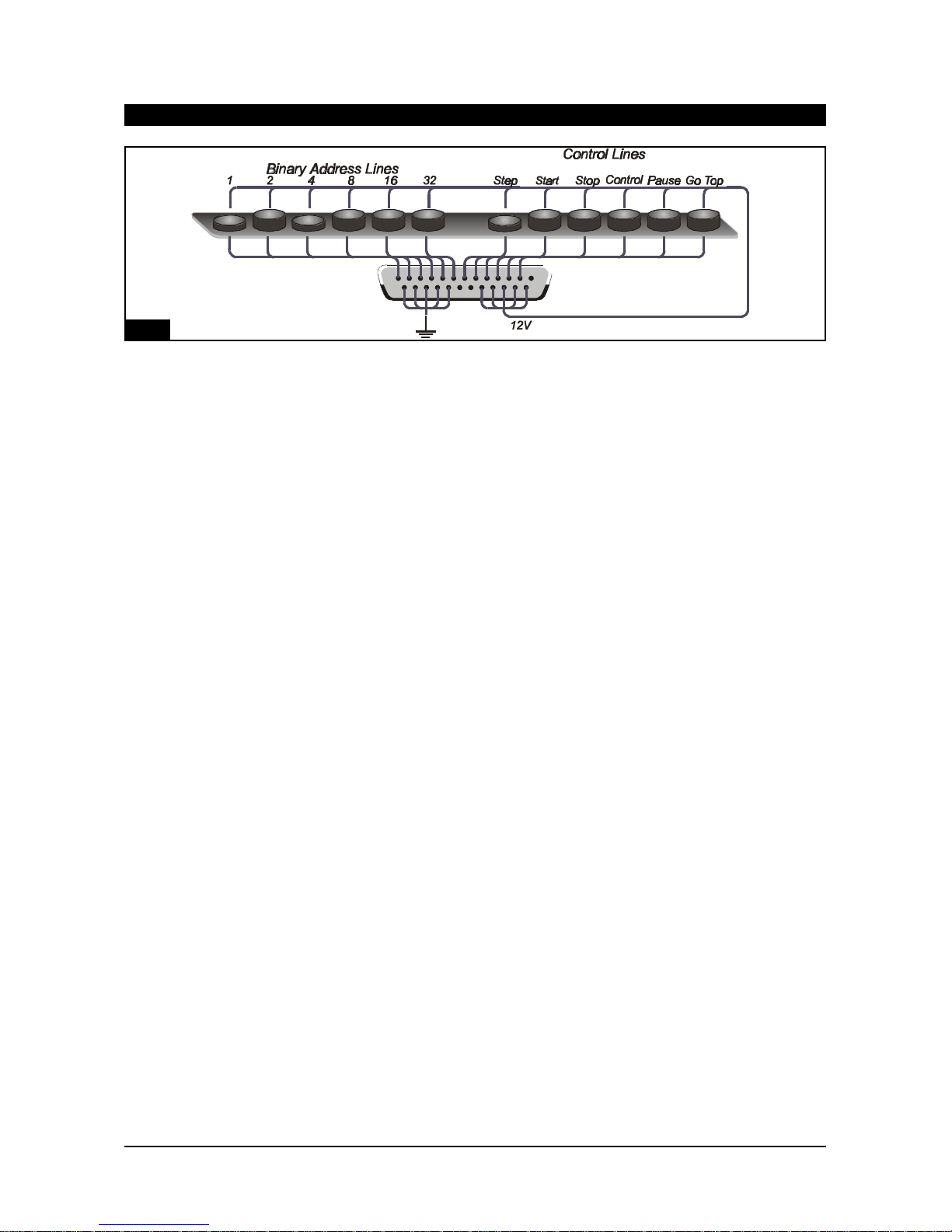
Note that linking pins 4 and 14 enables external control.
For stand-alone use and for automatic sequence starting it is sufficient to link pins 4 and 14 and pins 6 and
15.
MEMORY CARD
The memory card type is PCMCIA type 1, 256k (or greater) SRAM.
If the Store is in EXTERNAL CONTROL mode, the memory card is ignored. Otherwise, when the card is
inserted, the display shows Crd.
To Store to Card
Hold 4 pressed for two seconds. Sto appears in the display, followed by YES. If the card is
write-protected, Pro is seen in the display. The card stores all scenes, scene types, fade times and hold
times.
To Recall from Card
Hold AUTO pressed for two seconds. rcl appears in the display, followed by YES. If the card is
write-protected, Pro is seen in the display. All scenes, scene types, fade times and hold times are loaded
into the Store.
DMXCONNECTIONS
DMX connections to the QStore are via 5-pin XLR connectors, wired pin 1 = screen, pin 2 = data -,
pin 3 = data +. Pins 4 and 5 are not used.
LightProcessor DMXTools, April 2003
Page 12
Store
7
6
5
4
3
2
1
13
1425
Fig. 7
Page 16

The LightProcessor Rack- and Truss-Mounting Buffers are functionally identical.
Both products split, isolate, buffer and boost incoming DMX signals to four 1kV opto-isolated output
channels. See Fig. 8. They are designed to protect against DMX line faults, incorrect connection and earth
loops. Additionally they offer a means of Y-splitting a DMX signal and boosting DMX signals in very long
cable runs.
Each output channel comprises one 5-pin XLR output and one 3-pin XLR connector. (Products with eight
5-pin XLRs or eight 3-pin XLRs are available to order). Since each of the output connectors is
independently driven, all eight outputs may be used.
INSTALLATION
Verify the Buffer's operating voltage before mounting. The truss mounting version should be mounted to
the truss/structure using a hook clamp attached to the M10 bolt on its top face. A suitable safety chain
should be passed around the truss/structure and through the safety loop on the Buffer.
Before installing the rackmounting version set its operating voltage, using the rear panel voltage selector
switch. The mains cable enters through the rear panel.
Both devices are supplied fitted with one metre of mains cable for connection to a suitable mains supply of
16A maximum.
The truss mounting version’s input and through DMX connections are made to the left hand side. The
outputs are on the bottom. For the rackmounting version all connections are made via the front panel.
The main DMX chain is connected via the 5-pin XLR input and through connectors, thus providing a signal
input to the Buffer and a loop out to the next DMX device in the chain. If the Buffer is the last device in the
DMX chain, the line should be terminated by pressing the DMX line termination switch.
Connect the devices to be protected to the output connectors. Note that up to eight devices may be
connected but that only four channels of opto-isolation are provided.
OPERATION
The input and through connectors are linked when the unit is not powered. When the unit is powered up a
relay switches a buffer in between the input and through connectors.
Each output channel is fitted with a red and a green LED. These LEDs mimic the activity of the data true
and data invert DMX lines and flash rapidly during normal operation. Absence of this flashing in one LED
indicates a fault on that line. No flashing of either LED probably indicates an absence of DMX.
LightProcessor DMXTools, April 2003
Page 13
Buffer, Rack and Truss-mounting
Page 17

LightProcessor DMXTools, April 2003
Page 14
Buffer, Rack and Truss-mounting
ShieldData -
Data +
Not usedNot used
Shield
Data -
Data +
Not used
Not used
DMX IN
DMX OUT
5
5
5
5
3
3
3
3
Complete Electrical
Isolation
Link out
Terminate
0V
120
Fig. 8
Page 18

The Merge takes two DMX data stream inputs and combines them into a single DMX output data stream.
Additionally, a 24-channel analogue data stream may be input, multiplexed and merged with the master
DMX output.
Where there are multiple inputs to a single output channel, it is the highest level signal received that is
output (HTP).
Inputs may be offset, one from another, to begin at any point in the output stream. Inputs may also be
truncated, so that only a selected number of channels is added to the output.
The input DMX signal lines are opto-isolated to provide a high degree of isolation between data paths.
OPERATING VOLTAGE
The Merge is designed to operate on 230V AC. A 115V version is available to order.
MOUNTING
The Merge mounts in a standard 19 inch rack. It is one rack unit high.
HARDWARE CONNECTIONS
All connections are made via the rear panel.
MAINS INPUT
Fit an appropriate mains plug and connect to the mains. In the UK the plug should be fitted with a 3Amp
fuse.
CONTROL INPUTS
DMX input is via two XLR5 male connectors, wired according to the USITT(1990) protocol.
Analogue input is 0 to +10V via a 25-pin sub-D (male) connector. Channel connection details are shown in
Fig. 9 below.
DMX OUTPUT
The DMX output is via an XLR5 female connector, wired according to the USITT(1990) protocol.
OPERATION
When power is applied to the Merge, the letters 'run' will appear in the display.
If no offsets are programmed, the second DMX input stream is superimposed directly on the first and
output will occur according to the highest takes precedence rule, i.e. the highest of the two DMX input
levels and the analogue input will be output.
LightProcessor DMXTools, April 2003
Page 15
Merge
Fig. 9
Page 19

OFFSETS
The setting of offsets may best be illustrated by using an example, as described below and shown in
Fig. 10.
Assume that you wish to merge the outputs from
(a)a 256-channel DMX desk (Input 1)
(b)a 24-channel DMX desk (Input 2)
(c)a 12-channel analogue desk (Analogue)
To clear any previous programming of offsets, select the input you wish to clear by pressing either In1, In2
or Ana and then hold down + and - together until CLR appears in the display.
LightProcessor DMXTools, April 2003
Page 16
Merge
DMX input 1
(512 channels)
256 channel desk
First channel = 1
Last channel = 256
DMX input 2
(512 channels)
24 channel desk
First channel 257
Last channel 280
2
5
6
c
h
a
n
n
e
l
s
o
f
D
M
X
0
l
e
v
e
l
4
8
8
c
h
a
n
n
e
l
s
o
f
D
M
X
0
l
e
v
e
l
For these overlapping channels
the Qmerge compares
DMX Input 2 and the Analogue Input
and outputs the higher level
DMX Output Stream, 512 channels
Desk 2 channel
level information
12 chan.
analogue desk
Analogue input
(24 channels)
12 channel desk
First channel 281
Last channel 292
2
4
c
h
a
n
n
e
l
s
o
f
a
n
a
l
o
g
u
e
d
a
t
a
12 channels of
analogue 0 level
Desk 1 channel
level information
5
1
2
c
h
a
n
n
e
l
s
o
f
D
M
X
d
a
t
a
5
1
2
c
h
a
n
n
e
l
s
o
f
D
M
X
d
a
t
a
Fig. 10
Page 20

EXAMPLE
Input 1
Object
By default there is no offset and input 1 may be taken as the reference point beginning at channel
1 of the output stream. Channel 1 is therefore the FIRST CHANNEL. Since the desk used in the
example only has 256 channels, it can be assumed that channels 257 to 512 of the 512-channel
DMX signal will all be at level 0. Such information has no value, so we can set channel 256 as
LAST CHANNEL .
Method
Display shows 'run'.
Press button I1. Display shows 'in1'.
Press FIRST CHAN. Display shows '001'. If it shows any other channel no., use the ± buttons to
select channel '001'.
Press SAVE.
Press LAST CHAN. Display shows '512'.
Press '±' to change the channel number until '256' is displayed.
Press SAVE. Display shows 'Sto' and then reverts to 'run'.
Input 2
Object
We want the output from our 24-channel DMX desk to follow on after the 256-channel controller.
We therefore need to program an offset to begin output at channel 257. Since the desk gives 24
channels of meaningful output (and the rest of the 512 channels of the DMX signal will be output
as 0), we can truncate the output to 24 channels.
Method
Display shows 'run'.
Press button I2. Display shows 'in2'.
Press FIRST CHAN. Display shows '001'.
Press '±' to change the channel number until '257' is displayed.
Press SAVE.
Press LAST CHAN. Display shows '512'.
Press '±' to change the channel number until '280' is displayed.
Press SAVE. Display shows 'Sto' and then reverts to 'run'.
Analogue
Object
We want the output from the 12-channel analogue desk to follow on after the 24-channel DMX
desk. We therefore need to program an offset to begin output at channel 281 and finish at 292.
Method
Display shows 'run'.
Press button Ana. Display shows 'AnA'.
Press FIRST CHAN. Display shows '001'.
Press '±' to change the channel number until '281' is displayed.
Press SAVE.
Press LAST CHAN. Display shows '24'.
Press '±' to change the channel number until '292' is displayed.
Press SAVE. Display shows 'Sto' and then reverts to 'run'.
NOTE:The analogue FIRSTCHANNEL and LASTCHANNEL must be no more than 24 channels
apart; any channels greater than analogue FIRSTCHANNEL+ 24 will contain unpredictable data.
LightProcessor DMXTools, April 2003
Page 17
Merge
Page 21

DMuX
Power Supply: 230V AC 50-60Hz (115V AC 50-60Hz version available on request)
Signal Input: USITT DMX512 (1990)
Input Socket (Front) DMX512 via 5-pin XLR
Input Socket (Rear) DMX512 via 3-pin XLR
Link through (Front) DMX512 via 5-pin XLR
Link through (Rear) DMX512 via 3-pin XLR
Signal Output +10V DC analogue (-10V version available) 10mA per channel
Output Sockets (Front) 4 x 8-pin locking DIN socket (female)
Output Sockets (Rear) 6 x 5-pin DIN socket (female) and 4 x 8-pin locking DIN socket (female)
Dimensions 1U (44mm) x 19" (482mm) x 165 mm
Weight 3.5Kg
Store
Power Supply 230V AC 50-60Hz (115V AC 50-60Hz version available on request)
Lighting Channels 512
Control Channels 6-Binary address, 6-Control functions
Signal Input (Lighting) USITT DMX512 via 5-pin XLR
Signal Input (Control) 0-10V DC via 25 pin sub-D connector
Signal Output (Lighting) USITT DMX512 via 5-pin XLR
Signal Output (Control) Nominal 12V DC @ 30mA max
Memory 64 scenes of 512 channels. Memory may be saved to PCMCIA card.
Dimensions 1U (44mm) x 19" (482mm) x 165 mm
Weight 3.5Kg
Buffer
Power Supply 115/230V AC 50-60Hz (selectable)
Signal Input USITT DMX512 via 5-pin XLR
Isolated Outputs 4 x 3-pin XLR and 4 x 5-pin XLR (all 5-pin version available on request)
Dimensions QBuffer - 338mm x 191mm x 59mm.
DMXDistibutor - 1U (44mm) x 19" (482mm) x 200 mm
Weight QBuffer - 4kg
DMXDistributor - 3.8Kg.
Fixing QBuffer - M10 bolt or optional wall mounting bracket
DMX Distributor - Rack mount
Merge
Power Requirements 230V AC 50-60Hz (115V AC 50-60Hz version available on request)
Signal Inputs USITT DMX512 (1990), via 5-pin XLR.
0 to +1 0V analogue via 25-pin sub-D connector.
Signal Output USITT DMX512 (1990), via opto-isolated 5-pin XLR.
Dimensions 1U (44mm) x 19" (482mm) x 208 mm
Weight 3.6kg
Environmental - All Products
Temperature 0-30°C
Relative humidity 0-90% non-condensing
Pollution Degree 2
Protection Classification IP30
Conformance Designed to meet CE regulations covered by:
LVD (EN60950)
EMC (BSEN50081-1 and BSEN50082-1)
LightProcessor DMXTools, April 2003
Page 18
SPECIFICATIONS
Page 22

PRODUCTITEM REFERENCE
DMuX
Fuse, electronics F0.25MA2AS
Transformer T30VATRX
Store
Switch, front panelSM12SWITCH
Switch Cap CCD4GREY
Memory Card PCMCIA/512
Slider, 20K, linear P20KLINSLI
Buffer
Fuse, electronics F200MA2AS
Opto Isolator 6N137
Transformer T9V3VATRX
Merge
Switch, front panel924-933
Switch cap 925-019
Transformer T6VA/9-0-9
SPARE PARTS
LightProcessor DMXTools, April 2003
Page 19
Page 23

WARRANTY STATEMENT
LightProcessor provides a warranty against manufacturing defects for all Products for a period of eighteen months from date of
shipping to the Customer provided that the Products have not been subjected to any unauthorised modification or repair.
LightProcessor shall not be liable to the Customer by reason of any representation or any implied warranty, condition or other term or
any duty at common law for any indirect, special or consequential loss or damage, costs, expenses, or other claims for compensation
whatsoever which arise out of or in connection with the sale or supply of the Products or their use or resale by the Customer.
All items added to the Product by the Customer, it's agents or customers, must be removed from the Product prior to return to
LightProcessor. The return of the Product shall authorise LightProcessor to remove any such items. LightProcessor shall not be
obliged to reconnect any such items before returning the Product. LightProcessor will not be under any liability in respect of such
items.
The liability of LightProcessor to its Customers for death or personal injury resulting from our negligence is unlimited. Apart from that,
LightProcessor will not in any event be liable to its Customers for indirect or consequential loss, and any liability on behalf of
Lightprocessor for any loss or expense shall be limited to the contract price of the defective goods.
The cost of shipping defective Product back to LightProcessor is borne by the Customer. The cost of shipping back to the Customer is
borne by LightProcessor.
LightProcessor reserves the right either to repair or replace any defective Product
Prior to any Product being shipped for warranty repair or replacement the Customer must have applied for a "Warranty
Authorisation Number". These can be obtained from the Sales Administration Manager at LightProcessor's Head Office.
LightProcessor will then issue a 'Warranty Fault Report' that must be completed in all respects by the Customer. Failure to complete
the 'Warranty Fault Report' may cause delays in processing the repair of the Product.
The completed 'Warranty Fault Report' may either be Faxed, E-Mailed, Mailed or accompany the Product when it is returned
LightProcessor will advise the Customer within 1 working day of the receipt of the Product or the Warranty Fault Report, whichever is
the later, whether or not its accepts that the Product is covered under Warranty.
Warranty Repairs will be completed within 2 working days, subject to spare parts being available, and will be returned to the
Customer without delay.
Should a Product be returned for repair in damaged packaging or other than its original, LightProcessor reserves the right to
re-package the Product in its correct packaging and to charge £20.
Prior to any Product being shipped for repair the Customer must have applied for a "Repair Authorisation Number". These can be
obtained from the Sales Administration Manager at LightProcessor's Head Office.
LightProcessor will then issue a 'Repair Fault Report' that must be completed in all respects by the Customer. Failure to complete the
'Repair Fault Report' may cause delays in processing the repair of the Product.
The completed 'Repair Fault Report' may either be Faxed, E-Mailed, Mailed or accompany the Product when it is returned
LightProcessor will advise the Customer within 5 working days of the receipt of the Product or the Repair Fault Report, whichever is
the later, the Estimated Cost of Repair excluding labour and carriage.
Non-Warranty Repairs will be completed within 10 working days of receipt by the Customer of the Repair Cost Estimate, subject to
spare parts being available, and will be returned to the Customer without delay.
Should a Product be returned for repair in damaged packaging or other than its original, LightProcessor reserves the right to
re-package the Product in its correct packaging and to charge £20.
WARRANTY REPAIRS PROCEDURE
NON-WARRANTY REPAIRS PROCEDURE
LightProcessor DMXTools, April 2003
Page 20
Page 24

QCommander 256 (standard and extended models)
QCommander 512 (standard and extended models)
Replica memory store and playback unit
•Paradime digital dimmer range
•Analogue and DMX 2-preset desks
Q12
•Analogue and DMX 1-preset desks
Zip 6
Zip 18
www.lightprocessor.co.uk
info@lightprocessor.co.uk
Note the serial numbers of the products in this installation and quote
them when seeking help.
 Loading...