

LightPointe AireLink 60, AireLink 60 LX, AireLink 60 SX, AireLink 60 MX Installation And User Manual

LightPointe - AireLink 60 Installation and User Manual

AireLink 60 Installation and User Manual Rev. C
COPYRIGHTS AND DISCLAIMER
2015, LightPointe. All Rights Reserved
Information in this document is provided in connection with LightPointe products. These
materials are provided by LightPointe as a service to its customers and may be used for
information purposes only. LightPointe assumes no responsibility for errors or omissions in
these materials. LightPointe may make changes to specifications and product descriptions at
any time, without notice. LightPointe makes no commitment to update the information and
shall have no responsibility whatsoever for conflicts or incompatibilities arising from future
changes to its specifications and product descriptions.
No license, express or implied, by estoppel or otherwise, to any intellectual property rights is
granted by this document. Except as provided in LightPointe Terms and Conditions of Sale for
such products, LightPointe assumes no liability whatsoever.
These materials are provided “as is” without warranty of any kind, either expressed or implied,
relating to sale and/or use of LightPointe products including liability or warranties relating to
fitness for a particular purpose, consequential or incidental damages, merchantability, or
infringement of any patent copyright or other intellectual property right. LightPointe further
does not warrant the accuracy or completeness of the information, text, graphics or other
items contained within these materials. LightPointe shall not be liable for any special, indirect,
incidental, or consequential damages, including without limitation, lost revenues or lost
profits, which may result from the use of these materials.
The Bluetooth application provided with the system includes software code developed
partially under an MIT open software license agreement.
LightPointe products are not intended for use in medical, lifesaving or life sustaining
applications. LightPointe customers using or selling LightPointe products for use in such
applications do so at their own risk and agree to fully indemnify LightPointe for any damages
resulting from such improper use or sale.
The following are trademarks of LightPointe Product names or services listed in this publication
are for identification purposes only, and may be trademarks of third parties. Third-party
brands and names are the property of their respective owners.
FligħtLite, FligħtStrata, FligħtManager, AireLite, AireLink™, AireStrata, AireForce,
DualPath™, AireManager and Airelink are trademarks of LightPointe.
LightPointe believes the printed matter contained herein to be accurate from date of
publication and reserves the right to make changes as necessary without notice.
Page ii

AireLink 60 Installation and User Manual Rev. C
Reader Response: LightPointe strives to produce quality documentation and welcomes your
feedback. Please send comments and suggestions to LightPointe. For technical questions,
contact your local LightPointe sales office or field applications engineer.
Page iii

AireLink 60 Installation and User Manual Rev. D
Introduction
TABLE OF CONTENTS
1 Introduction 18
1.1 Shipping Content 18
1.1.1 AireLink™ 60 with integrated antenna 18
1.1.2 AireLink™ 60 with external antenna: 20
1.2 Main Radio Components 21
1.2.1 AireLink™ 60 ODU with integrated antennas 21
1.2.2 AireLink™ 60 ODU with external antennas 22
1.2.3 External Antennas and Mounting Brackets 23
1.2.4 Power over Ethernet (PoE) Modules 24
1.2.5 Miscellaneous 25
1.2.5.1 RSSI Alignment Cables 25
1.2.5.2 Lightning/ Surge Protection 25
1.2.5.3 Optional: Ethernet Cable Extender 26
1.2.5.4 Optional: Antenna Alignment Tool 26
1.2.5.5 Optional: Weather shield for SX model 27
2 Surveying the Installation Site 29
2.1 Tools 29
2.2 Installation Site Review 29
2.3 Link Distance 31
2.4 Antenna Location 32
2.5 Atmospheric and Rain Attenuation of Millimeter Wave Beams 32
3 Networking, Power and Service Connections 41
3.1 AireLink™ 60 User Panel 41
3.2 Power Connection 44
3.2.1 Powering via PoE 44
3.2.2 Powering via Direct 48 Vdc 45
3.3 Grounding/ Lightning protection 46
3.4 Network Data Connection 48
3.5 Out-Of-Band Management Connection 49
3.6 Console Port 49
3.7 RSSI Voltage Connector 49
3.8 Bluetooth Antenna Connector 50
4 Recommended Software Pre-Configurations 52
4.1 Required Network Settings Info 52
4.2 Airelink Configuration via TELNET CLI INTERFACE 52
Page 4

AireLink 60 Installation and User Manual Rev. D
Introduction
5 System Installation 57
5.1 Tools 57
5.2 Universal Mount Assembly 58
5.3 Pole Mount Installation of Airelink 60 with Integrated Antenna 59
5.4 Pole Mount Installation of Airelink 60 with External Antenna 60
5.5 ODU Installation (External Antenna System only) 61
5.6 System Alignment Basics 62
5.7 Antenna Radiation Pattern and Side Lobes 63
5.8 Installing Airelink™ 60 with Integrated 12 cm Antenna 64
5.9 Installing Airelink™ 60 with External Antennas 70
5.10 Installing the Optional Alignment Sight Tool for External Antennas 70
5.11 Airelink™ 60 with 1 Foot Antenna 70
5.12 Airelink™ 60 with 2 Foot Antenna 72
5.13 Configuration of the Alignment Sight Tool 72
5.14 Mounting Bracket Adjustment 73
5.15 Aligning the 60 Ghz Antennas 75
6 LinkManager™– Network Management Platform 82
6.1 Management Application Views 82
6.2 System View 84
6.3 RF LINK VIEW 85
6.4 PORT STATUS View 86
6.5 Management View 89
6.6 PERFORMANCE View 90
6.7 STATISTICS View 91
6.8 SNMP View 92
6.9 SOFTWARE View 93
6.10 ADMINISTRATION 94
7 CLI -- Command Line Interface 95
7.1 User Mode Commands 96
7.2 CLI – SHOW Command 96
7.2.1 Command Show Flash 97
7.2.2 Command Show Interface 97
7.2.3 Command Show Performance 98
7.2.4 Command Show Radio 98
7.2.5 Command Show SNMP 99
7.2.6 Command Show System 99
Page 5

AireLink 60 Installation and User Manual Rev. D
Introduction
7.2.7 Command Show Versions 100
7.2.8 Command Show VLAN 100
7.3 CLI --Configuration Commands 100
7.3.1 Interface Commands 101
7.3.1.1 Interface data commands 101
7.3.1.2 Interface management commands 102
7.3.2 Password Command 104
7.3.3 Performance Commands 104
7.3.4 Radio Commands 105
7.3.5 SNMP Commands 107
7.3.6 System Commands 108
7.3.7 Reboot Command 109
7.3.8 Exit Command 109
7.4 CLI -- Save Session Settings on Flash and sOFTWARE Upgrade 109
7.5 CLI -- PING Command 110
7.6 CLI – Upgrade TFTP Command 110
7.7 CLI – LOG Command 110
8 Bluetooth AireLink Viewer 113
9 SNMP 117
9.1 Basics 117
9.2 LightPointe MIB Files 117
9.3 LightPointe MIB Tree 118
9.4 SNMP Trap Monitoring 120
10 Troubleshooting and Diagnostics 122
10.1 Failure Types 122
11 Advanced Troubleshooting Methods 126
11.1 Performing a PING Test 126
11.2 Equipment Connection and Network Settings 126
11.3 Step-by-Step Instructions to Perform a PING Test 127
11.4 BER Testing 128
12 Specifications 130
13 Technical Support 131
13.1 Return Material Authorization (RMA) Procedure 132
13.2 Contacting LightPointe 132
Page 6

AireLink 60 Installation and User Manual Rev. D
Introduction
LIST OF FIGURES
Figure 1-1: AireLink™ 60 with integrated antenna (left) and accessories (next page) .................. 19
Figure 1-2: Shipping Box 1 (AireLink™ 60 detachable ODU and accessories) .............................. 20
Figure 1-3: Shipping Boxes 2 and 3 (1 foot antennas) ............................................................ 20
Figure 1-4: Shipping Boxes 2 and 3 (2 foot antennas) ............................................................. 21
Figure 1-5: AireLink™ 60 with integrated antenna and view of access panel cover ....................... 22
Figure 1-6: AireLink™ 60 ODU ............................................................................................. 22
Figure 1-7: AireLink™60 with one foot (top) and two foot (bottom) antennas attached. ............... 23
Figure 1-8: Alignment bracket and locations of alignment screws .............................................. 23
Figure 1-9: Power over Ethernet modules ............................................................................... 24
Figure 1-10: Optional dc power supply ................................................................................... 24
Figure 1-11: RSSI alignment cables ....................................................................................... 25
Figure 1-12: Surge Protectors ............................................................................................... 26
Figure 1-13: Ethernet Cable Length Extender ......................................................................... 26
Figure 1-14: Alignment Tool for integrated (left) and external Antenna (right) ............................ 27
Figure 1-15: Side and front view of AireLink 60-SX with optional weather shield installed. ............ 27
Figure 2-1: Fresnel Zone illustration. ..................................................................................... 30
Figure 2-2: Atmospheric attenuation of signals at different frequencies. ..................................... 32
Figure 2-3: ITU rain zone chart of the earth ........................................................................... 33
Figure 2-4: AireLink™ 60 Distance vs. Availability North America .............................................. 35
Figure 2-5: AireLink™ 60 Distance vs. Availability Europe........................................................ 37
Figure 2-6: AireLink™ 60 Distance vs. Availability Australia ..................................................... 38
Figure 2-4: Typical AireLink™ 60 RSSI vs. Distance chart ......................................................... 39
Figure 3-1: AireLink™ 60 User Panel with plastic cover removed ............................................... 42
Figure 3-2: AireLink™ 60 User panel ...................................................................................... 42
Figure 3-3: Powering via PoE ................................................................................................ 44
Figure 3-4: Direct 48 Vdc Power Connection ........................................................................... 46
Figure 3-5: Enclosure Ground Connection ............................................................................... 46
Figure 3-7: Lightning Protection Zones .................................................................................. 47
Figure 3-8: Data Network Connection .................................................................................... 48
Figure 3-9: RSSI Voltage Port Connector Location ................................................................... 49
Figure 3-10: Bluetooth antenna connection ............................................................................ 50
Figure 5-1: Assembled Universal Mount and Base Plate Hole Pattern ......................................... 58
Figure 5-2: ODU Polarization Directions ................................................................................. 61
Figure 5-3: AireLink™ 60 installed on LightPointe Universal Mount ............................................ 62
Figure 5-4: Typical antenna Radiation Pattern Envelope (RPE) diagram ...................................... 63
Figure 5-5: Alignment Sight Tool (Integrated Antenna System) ................................................ 65
Page 7

AireLink 60 Installation and User Manual Rev. D
Introduction
Figure 5-6: Antenna alignment scan ...................................................................................... 66
Figure 5-7: Simple illustration of the alignment process ........................................................... 67
Figure 5-8: Typical AireLink 60-SX RSSI vs. Distance Charts for standard distance setting ......... 68
Figure 5-9: Default User Panel status after successful alignment ............................................... 69
Figure 5-10: Alignment Sight Tool (External Antenna System) .................................................. 70
Figure 5-11: Attach Alignment Sight Tool to external 1 foot antenna ......................................... 71
Figure 5-12: Attach Alignment Sight Tool to external 2 foot antenna ......................................... 72
Figure 5-13: Re-configuring Alignment Sight Tool.................................................................... 72
Figure 5-14: Elevation Adjustment ........................................................................................ 73
Figure 5-15: Azimuth Adjustment .......................................................................................... 74
Figure 5-16: Antenna alignment scan .................................................................................... 77
Figure 5-17: Simple illustration of the alignment process ......................................................... 78
Figure 5-18: Typical AireLink 60 MX/LX RSSI vs. Distance Charts for stand distance settings ........ 79
Figure 5-19: Default User Panel status after successful alignment ............................................. 79
Figure 6-1: LinkManager™ Login Window .............................................................................. 82
Figure 6-2: LinkManager Registration Screen ......................................................................... 82
Figure 6-3: LinkManager™ Main Screen ................................................................................ 83
Figure 6-4: System View Screen .......................................................................................... 84
Figure 6-5: RF Link View Screen........................................................................................... 85
Figure 6-6: Port Status View (RJ45 Data Port) ....................................................................... 86
Figure 6-7: Port Status View (SFP Data Port) ......................................................................... 87
Figure 6-8: Port Status View (RJ45 Management Port) ............................................................ 88
Figure 6-9: Management View Screen ................................................................................... 89
Figure 6-10: Performance View Screen ................................................................................. 90
Figure 6-11: Statistics View Screen ...................................................................................... 91
Figure 6-12: SNMP View Screen ........................................................................................... 92
Figure 6-13: Software View Screen ...................................................................................... 93
Figure 6-14: Administration View Screen ............................................................................... 94
Figure 9-1: LightPointe MIB modules ................................................................................... 117
Figure 9-2: MIB tree iso/org/dod/internet/private/enterprises/lpcomm .................................... 118
Figure 9-3: Detailed view of LPCOMM MIB tree ..................................................................... 119
Figure 9-4: Performance Graph ........................................................................................... 120
Figure 9-5: SNMP Traps ..................................................................................................... 120
Page 8

AireLink 60 Installation and User Manual Rev. D
Introduction
LIST OF TABLES
Table 2-1 Fresnel zone path clearan .................................................................................... 30
Table 2-2: Rain rates, duration and 60 GHz signal attenuation ............................................... 34
Table 3-1: User Panel Connections and Status LEDs .............................................................. 43
Table 9-1: Troubleshooting Chart I ................................................................................... 123
Table 9-2: Troubleshooting Chart II .................................................................................. 124
Page 9
AireLink 60 Installation and User Manual Rev. D
Introduction
Exercise caution when you see this symbol. It indicates actions that
could be harmful to the installer or to the equipment.
Prenez garde lorsque vous voyez ce symbole, il s'agit d'un
avertissement indiquant qu'il y a danger pour l'installateur ou
l'equipement.
Exercise extreme caution when you see this symbol. It indicates
potentially lethal voltages!
Soyez extremement prudent lorsque vous voyez ce symbole, il
s'agit d'un avertissement denotant la presence de haut voltage
pouvant causer la mort ou des blessures graves.
INFORMATION TO USER
NOTE: CHANGES OR MODIFICATIONS OF THE SYSTEM NOT EXPRESSLY APPROVED BY
LIGHTPOINTE COULD VOID THE USER'S AUTHORITY TO OPERATE THE EQUIPMENT.
Cautions and Warnings
The following symbols are used in this manual to indicate that the installer should take particular
caution to prevent injury or damage to the equipment.
Note: There are no serviceable parts within the units and the system should not be opened in the
field.
Observe Standard Precautions
All persons having access to this equipment must observe all standard precautions as defined in
applicable national statutory health and safety legislation.
The outdoor equipment must be properly protected against voltage surges and prevent the built-up of
static electric charges. We recommend following the IEC 61024/ IEC 62305 standards for proper
lightning protection.
For installations in the U.S.A., for information with respect to proper grounding and applicable lightning
protection for DC cables please refer to Articles 810830 of the National Electrical Code, ANSI/NFPA No.
70.
In case the system is installed in a country outside of the U.S.A., implement protection in accordance
with local safety standards and regulatory requirements.
Page 10

AireLink 60 Installation and User Manual Rev. D
Introduction
Do not install or operate this equipment in the presence of or close to flammable gases or fumes.
Operation of any electrical equipment in such an environment constitutes a potential safety hazard.
Qualified Personnel
Qualified personnel who understand and are trained to work with the equipment must perform all
repair, modification, reconfiguration, and upgrading operations.
Note: Always power the system down before moving or removing the system.
Service
There are no serviceable parts within the radio units. Only factory trained personnel can provide service
on any internal components of the radio units.
Export Control
All LightPointe AireLink™ radio products are commodities that fall under ECCN 5A002 of the
Department of Commerce. These products are "ENC restricted" under section 740.17(b)(1) of the
Export Administration Regulations (EAR). This License Exception ENC does not authorize export or reexport to, or provision of any service in any country listed in Country Group E:1 in Supplement No. 1
to part 740 of the EAR. Diversion contrary to U.S. law is expressly prohibited.
Regulatory Information
North America:
These devices have been type approved by FCC in accordance with 47 CFR PART 15.255 of the Federal
Communication Commission rules and Industry Canada RSS-210 Issue 8.
No license is required in the U.S. or Canada for millimeter wave radio transmission equipment operating
in the 57-64 GHz frequency band. Customers in other countries are responsible for obtaining proper
operator licenses in case they are required by law.
47 CFR Part 15.255
This device complies with Part 15.255 of the FCC Rules. Operation is subject to the following conditions:
This device may not cause harmful interference, and
This device must accept any interference received, including interference that may cause undesired
operation.
Page 11

AireLink 60 Installation and User Manual Rev. D
Introduction
Industry Canada RS210 Issue 8
This Class 1 digital apparatus complies with the Canadian RSS-210 regulation.
Cet appareil de la classe 1 est conforme à la norme RSS-210 du Canada.
European Union:
These devices are in compliance with the European Directive R&TTE 1999/5/EC on Radio Equipment
and Telecommunications Terminal Equipment and have been assessed against the following Applicable
Standards:
EN 302 217-3 V2.2.1 (2014-04)
R&TTE: EN 302 217-4-2 V1.5.1 (2010-01)
EN 301 489-1 V1.9.2 (2011-09)
EN 301-489-4 V2.2.0 (2015-01)
IEC/EN 60950-1:2005 (2nd Ed.), +A1: 2009, +A11:2009, +A12:2011
Environmental: This product is ROHS compliant
Other Recommendations and Selected National Standards
ECC/CEPT: ECC/REC/(09)01
Germany: SSB FE-OE 034 (Ausgabe 2/2012)
Notification number 2012/0245/D
Austria: FSB-RR072
Switzerland: RIR0302-47
Australia: Radcom LIPD LIC2000 Schedule 1, Item 51
Page 12
AireLink 60 Installation and User Manual Rev. D
Introduction
AT
BE
BG
CZ
DK
EE
FI
FR
DE
GR
IS
IE
LV
LT
LU
MT
NL
NO
PT
RO
SK
SI
SE
CH
UK
UNDER THE EUROPEAN COMMISSION ONE-STOP-NOTIFICATION (OSN) PROCESS,
NOTIFICATION #11474, THE NATIONAL REGULATORY AUTHORITIES OF THE
FOLLOWING EUROPEAN MEMBER COUNTRIES HAVE BEEN NOTIFIED AND THE
EQUIPMENT MAY BE OPERATED IN THE FOLLOWING COUNTRIES:
RF Exposure evaluation
To ensure public safety requirements for installation of an RF system in an uncontrolled location, an
RF exposure calculation was performed by an independent and accredited test lab (NEMKO USA). The
results are presented below.
Safe distance according to FCC CFR 47 § 1.1307, §1.1310; and Industry Canada’s (IC)
RSS-102, Issue 5, Safety Code 6
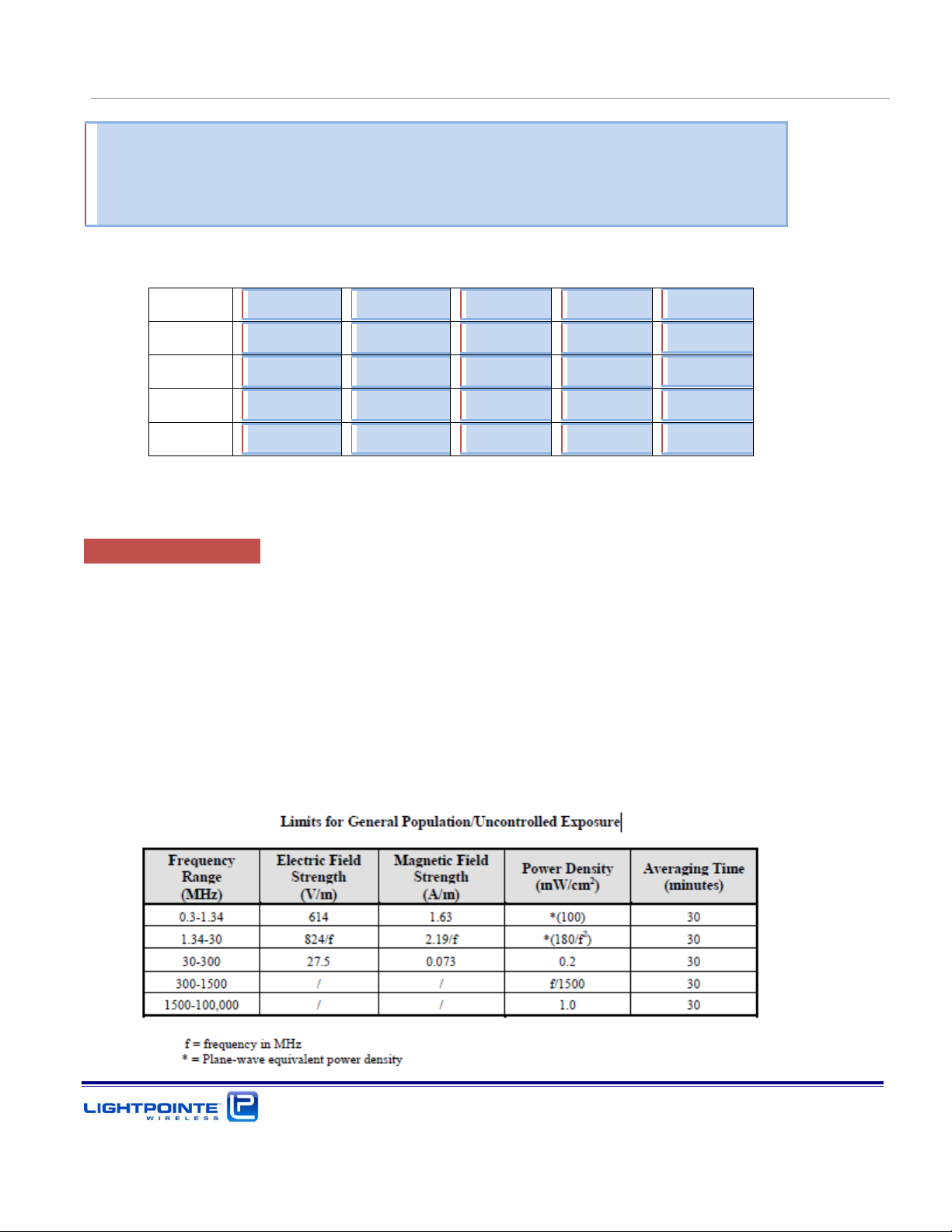
For the safety distance calculation the power density limits and average exposure time according to
the US FCC and Industry Canada IC regulation was taken into consideration. According to FCC § 1.1310
the limits for general population and uncontrolled exposure are as follows:
Page 13
AireLink 60 Installation and User Manual Rev. D
Introduction
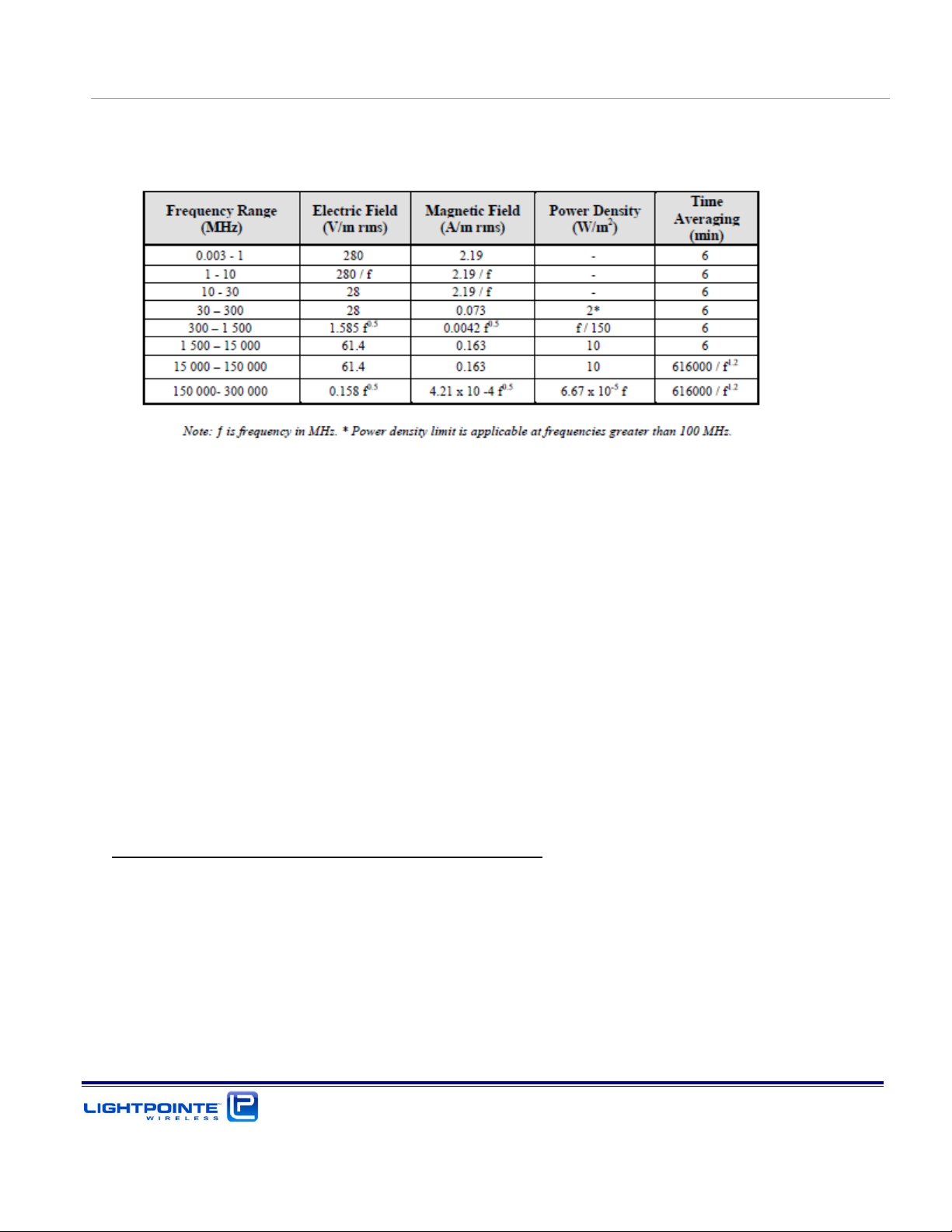
Industry Canada’s RSS-102 requirement are listed below and are slightly different from the FCC
regulation.
A calculation was perform to confirm the required safe distance for fixed service devices.
Limit for power density for general population/uncontrolled exposure was calculated for a power
density of max. 1 mW/cm2 and for the frequency range 1500 -100000 MHz.
The power density P (mW/cm2) = PT/ 4πr2, where
PT = the maximum equivalent isotropically radiated power (EIRP).
The minimum safe distance “r”, where RF exposure does not exceed the permissible limit, is:
r = sqrt { PT/ (Px4π)}
1. AireLink™ 60 SX system with 12 cm lens antenna
The maximum rms output power is 9.1 dBm and max antenna gain is 36 dBi. This corresponds to the
equivalent isotropically radiated power (EIRP) of 9.1 dBm + 36 dBi = 45.1 dBm, which is equal to
32359 mW.
r = sqrt { PT/ (Px4π)} = sqrt {32359 / 12.56} = 50 cm or 1.7 feet
Page 14
AireLink 60 Installation and User Manual Rev. D
Introduction
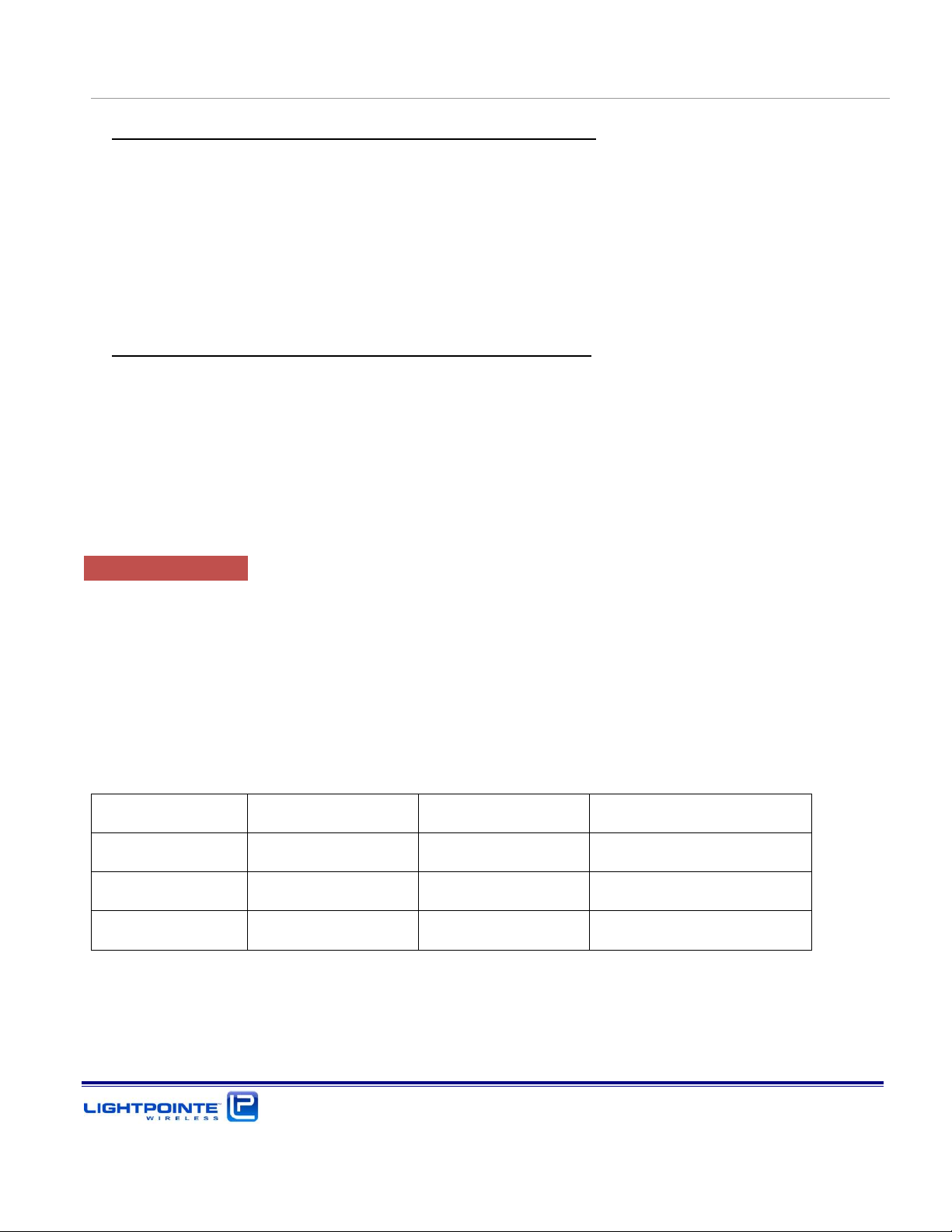
Configuration
Antenna size
Antenna gain
Minimum separation
AireLink™ 60 SX
12 cm
36 dBi
50 cm (1.7 feet)*
AireLink™ 60 MX
30 cm
42 dBi
100 cm (3.3 feet)*
AireLink™ 60 LX
60 cm
47 dBi
180 cm (6.0 feet)*
2. AireLink™ 60 MX system with 30 cm parabolic antenna
The maximum rms output power is 9.1 dBm and max antenna gain is 42 dBi. This corresponds to the
equivalent isotropically radiated power (EIRP) of 9.1 dBm + 42 dBi = 51.1 dBm, which is equal to
128825 mW.
r = sqrt { PT/ (Px4π)} = sqrt {128825 / 12.56} = 100 cm or 3.3 feet
3. AireLink™ 60 LX system with 60 cm parabolic antenna
The maximum rms output power is 9.1 dBm and max antenna gain is 47 dBi. This corresponds to the
equivalent isotropically radiated power (EIRP) of 9.1 dBm + 47 dBi = 56.1 dBm, which is equal to
407380 mW.
r = sqrt { PT/ (Px4π)} = sqrt {407380 / 12.56} = 180 cm or 6.0 feet
RF Exposure Summary
To comply with the FCC/IC RF exposure limits the device must be installed so as to maintain the
following minimum separation distance between the main lobe of the transmit antenna (front of the
antenna) and nearby persons. At these distances the average exposure time should be limited to 30
minutes (FCC) and 10 minutes (IC)
Pour se conformer aux limites d’exposition aux RF de RS-102, Issue 5, la distance minimale de
séparation entre la principale source d’émission (avant de l’antenne) et des personnes à proximité droit
être limité à:
*Average exposure time 30 minutes (FCC) or 10 minutes (IC).
Page 15

AireLink 60 Installation and User Manual Rev. D
Introduction
CE Declaration of Conformity
Date of Issue: 2015-04-01
We, LightPointe Communications, Inc., with address 11696 Sorrento Valley Road, Suite 101, San Diego, CA
92121 declares under our sole responsibility that:
Product Description: Point-to-Point Millimeter Wave Transmission System
Model Number(s): AireLink™ 60-xx
To which this declaration relates is in conformity with the following standard(s) or other normative
document(s) that this product has been assessed against the following Applicable Standards:
EN 302 217-3 v2.2.1 (2014-4)
EN 302 217-4-2 v1.5.1 (2010-01)
R&TTE: EN 301 489-1 V1.9.2 (2011-09)
EN 301 489-04 v2.2.0 (2015-01)
IEC/EN 60950-1:2005 (2nd Ed.), +A1: 2009, +A11:2009, +A12:2011
To which this declaration relates is in conformity with the provisions of the following Directives:
Directive R&TTE 1999/5/EC on Radio Equipment and Telecommunications Terminal Equipment
The CE Mark shall be affixed on the product as evidence of compliance to this declaration.
Declaration by:
Heinz Willebrand CEO & President
Name Title
_______________________________ 2015-04-01
Signature Date
Page 16

AireLink 60 Installation and User Manual Rev. D
Introduction
Warranty Information
LightPointe warrants this product against faulty materials or workmanship under the terms of a
Standard Warranty and Support Agreement provided that the product was purchased directly from
LightPointe or from one of our authorized resellers. Please contact LightPointe Customer Service for
additional information or to obtain a copy of the Warranty Agreement.
Contacting LightPointe
Corporate Office
11696 Sorrento Valley Road, #101
San Diego, California 92121
P: 858.834.4083
F: 858.430.3458
Website: Hwww.LightPointe.comH
Email: techsupport@LightPointe.com
Page 17
AireLink 60 Installation and User Manual Rev. D
Introduction
1 INTRODUCTION
Before starting to cover details on how to install the system we will briefly review the system
components included with the shipment and explain the basic principle of operation.
1.1 SHIPPING CONTENT
The AireLink™ 60 system is shipped with an integrated or an external antenna. Depending on the
system ordered packaging / box contents will be different.
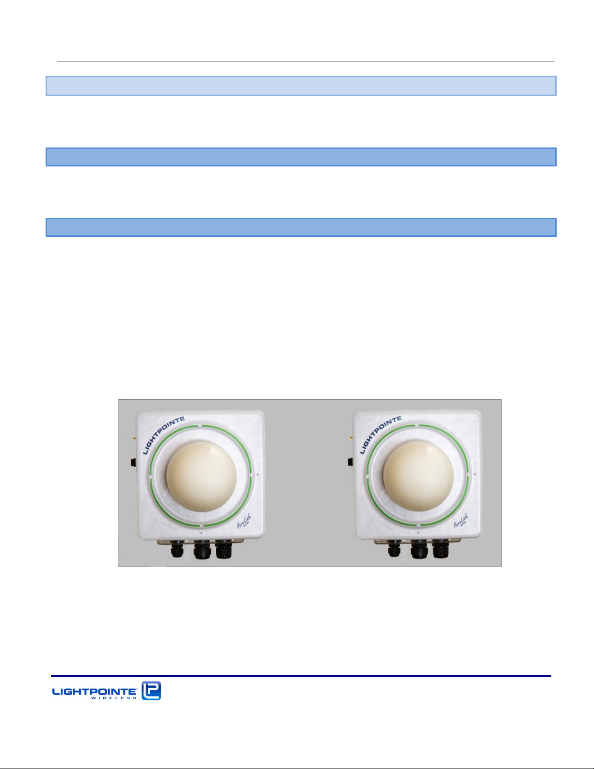
1.1.1 AireLink™ 60 with integrated antenna
The AireLink™ 60 SX ships in a single box. Please verify that the shipment contains the following items:
Two 60 GHz radios with integrated 120 mm lens antenna
Two mounting brackets
Two RSSI Alignment cables for use with voltmeter
Two ferrite beads
One Micro USB cable
Two Power over Ethernet (PoE) injectors (optionally: Two 48 Vdc outdoor rated power supplies)
Two Bluetooth rubber antennas with SMA connector
CD with Installation Manual
Figure 1-1: AireLink™ 60 with integrated antenna (top) and accessories (next page)
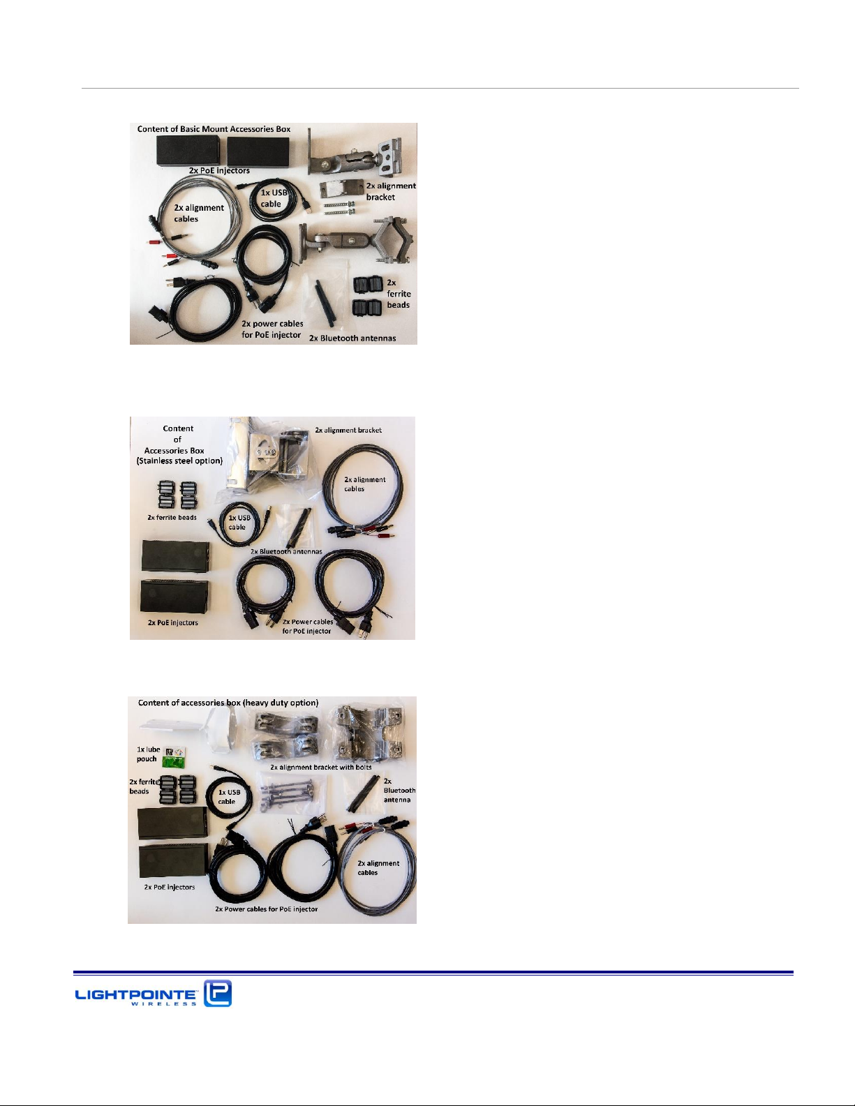
The AireLink™ 60 SX system ships with either of three alignment bracket options. Depending on which
bracket was ordered, the content of the accessories box will slightly vary:
Page 18
AireLink 60 Installation and User Manual Rev. D
Introduction
1. Basic alignment bracket accessories box
2. Stainless Steel alignment bracket accessories box
3. Heavy duty alignment bracket accessories box
Page 19
AireLink 60 Installation and User Manual Rev. D
Introduction
1.1.2 AireLink™ 60 with external antenna:
The AireLink™ 60 MX/LX with external antenna ships in three separate boxes. Please verify that the
shipment contains the following items:
Two detachable AireLink™ 60 outdoor radio transmission units (ODU)
Two Power over Ethernet (PoE) injectors (optionally: Two 48 Vdc outdoor rated power supplies)
Two RSSI Alignment cables for use with voltmeter
One Micro USB cable
Two Bluetooth rubber antennas with SMA connector
Two antennas (either 12” or 24”) w/attached side pole mounting bracket
CD with Installation Manual
Optional: Site Alignment Tool
The pictures below show the content of each individual shipping box.
Figure 1-2: Shipping Box 1 (AireLink™ 60 detachable ODU and accessories)
Figure 1-3: Shipping Boxes 2 and 3 (1 foot antennas)
Page 20
AireLink 60 Installation and User Manual Rev. D
Introduction
Figure 1-4: Shipping Boxes 2 and 3 (2 foot antennas)
1.2 MAIN RADIO COMPONENTS
The AireLink™ 60 comes either with an integrated 120 mm lens antenna or with external one or foot
high gain parabolic Cassegrain antennas.
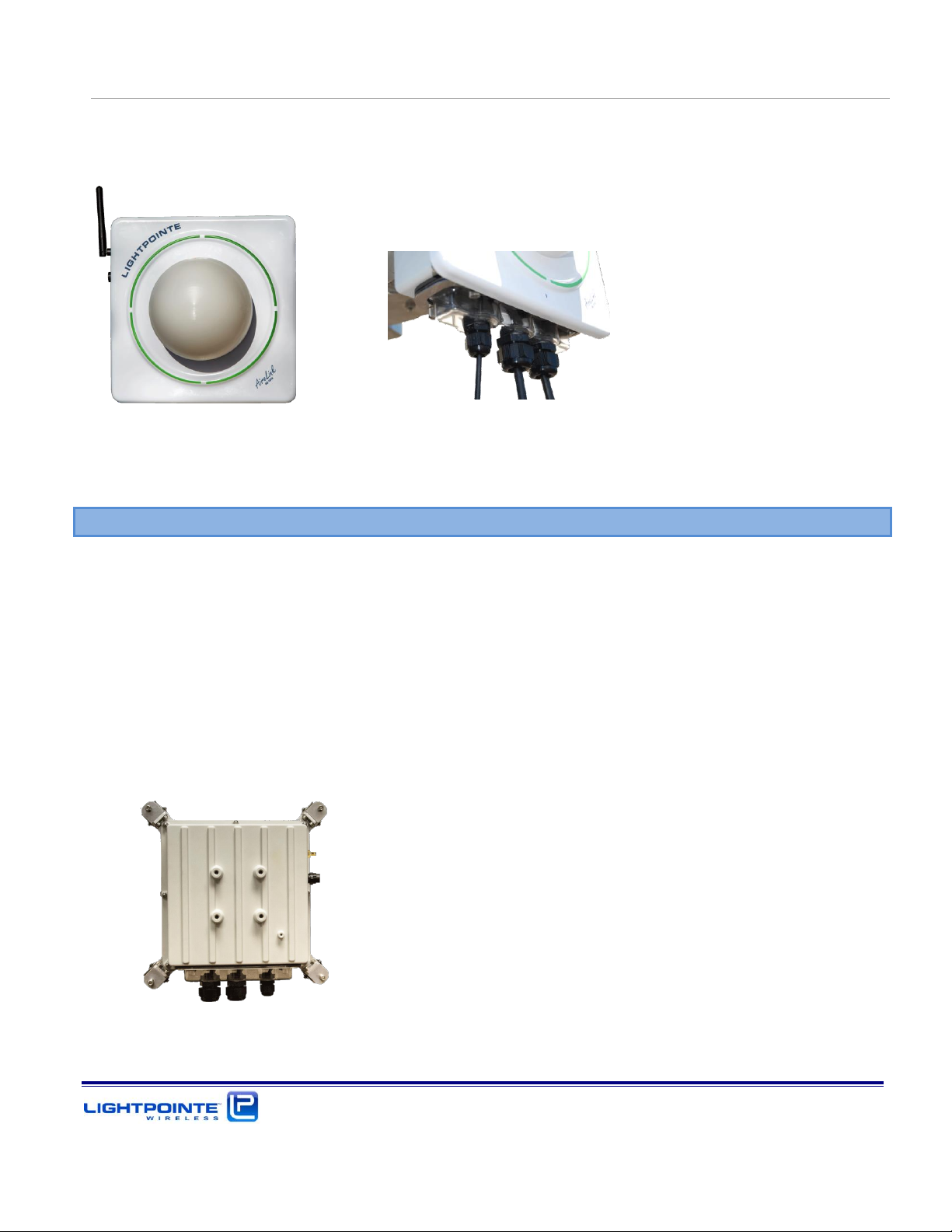
1.2.1 AireLink™ 60 ODU with integrated antennas
The AireLink™ 60 with integrated lens antenna shown in Fig. 1-5 is designed around an aluminumbased IP 66 rated outdoor housing to protect the electronics from rain, dust and other environmental
conditions. The system can be used to easily create a shorter distance point to point wireless Network
connection between remote locations. This highly integrated and outdoor rated system can be easily
installed at walls, towers or other structure by using the pole mount alignment bracket that comes
with the system. The stainless steel mounting bracket is designed to accommodate pole diameters
ranging from 2.5….4.5 inches (65…115 mm). All network/management and power connectors located
on the system user panel can be easily accessed via a clear and detachable access panel cover. Power
and port status LEDs on the back panel are visible from the outside through the transparent cover.
IP67 rated cable gland compression fittings for power/networking cables are integrated into the access
panel cover.
The transmission equipment operates in full-duplex mode and in slightly different frequency bands.
The lower band radio transmits in the 59 GHz frequency band and the upper band radio transmits in
the 62 GHz frequency band. On the back panel is a HIGH BAND and LOW BAND sticker to distinguish
between the radios. The AireLink™ 60 radios are equipped with a Bluetooth Low Energy (BLE)
transceiver that allows for remotely monitoring the radio via smart phone of tablet via an encrypted
Page 21
AireLink 60 Installation and User Manual Rev. D
Introduction
and password protected Bluetooth connection. Figure 1-5 shows the Bluetooth antenna attached to
the radio enclosure.
Figure 1-5: AireLink™ 60 with integrated antenna and view of access panel cover
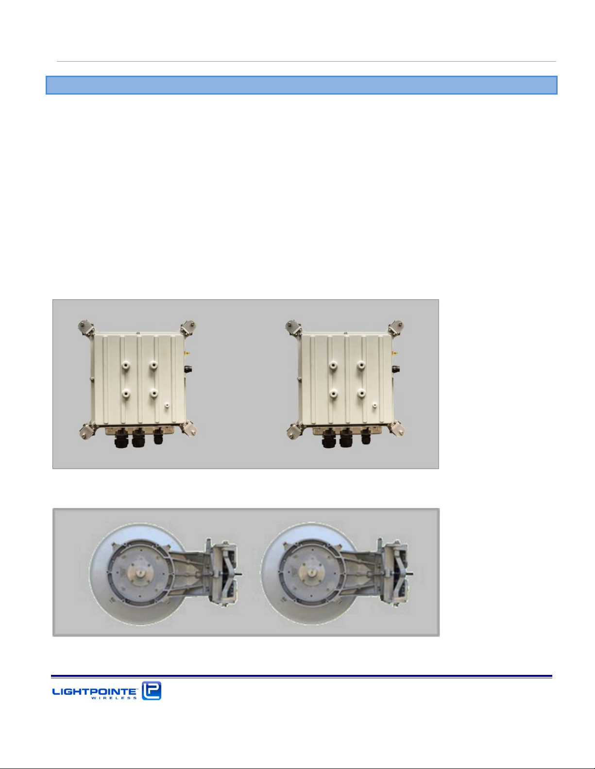
1.2.2 AireLink™ 60 ODU with external antennas
The longer distance version of the AireLink™ 60 comes with separate antennas and a detachable radio
outdoor unit (ODU). The ODU is contained within an aluminum-based IP 66 rated outdoor housing to
protect the electronics from rain, dust and other environmental conditions. Same as the integrated
antenna solution, the radios operates in full-duplex mode. A sticker on the back panel shows the HIGH
BAND and LOW BAND radio unit. The ODU is shown in Fig. 1-6. It can be easily detached from the
antenna by releasing the 4 spring loads latches and simply pulling the ODU of the antenna waveguide
flange. Same as the AireLink™ 60 radios with integrated antenna, the ODU is equipped with a
Bluetooth Low Energy (BLE) transceiver that allows for remotely monitoring the radio via smart phone
of tablet via an encrypted and password protected Bluetooth connection. The Bluetooth antenna has
ships with the system is attached to a SMA connector located at the side of the enclosure.
Figure 1-6: AireLink™ 60 ODU
Page 22

AireLink 60 Installation and User Manual Rev. D
Introduction
The ODU is fully IP 67 outdoor rated and all network/management and power connectors can be easily
accessed via a clear and detachable access panel cover. The transparent cover also allows the see all
network port status indicators. The ODU can be easily removed from the antenna waveguide by
releasing 4 spring loaded latches. The ODU is the same for both, the 1 foot and the 2 foot antenna
system. By rotating the ODU 90 degrees the polarization can be changed easily. Chapter 4 describes
the ODU Networking, Service and Power Connections in more detail.
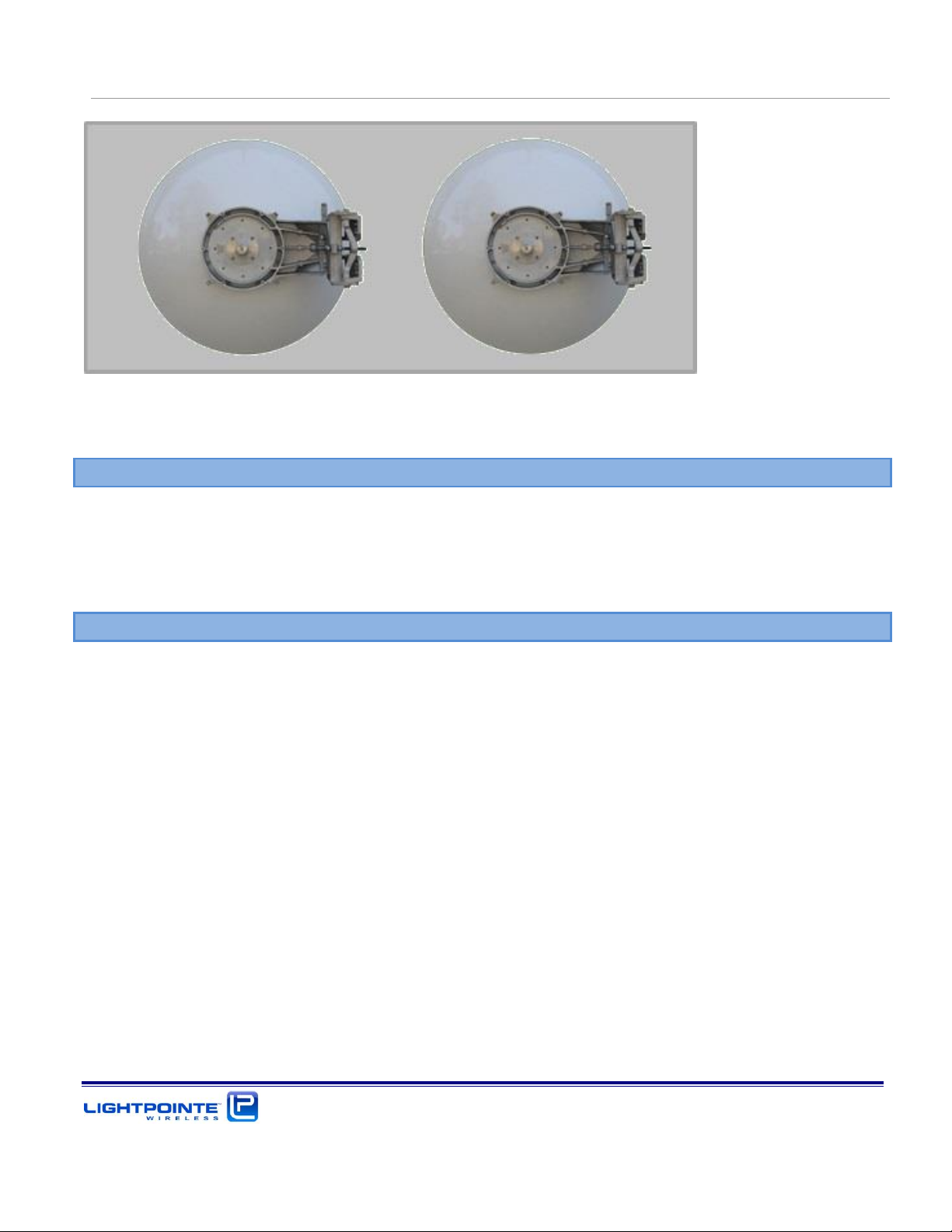
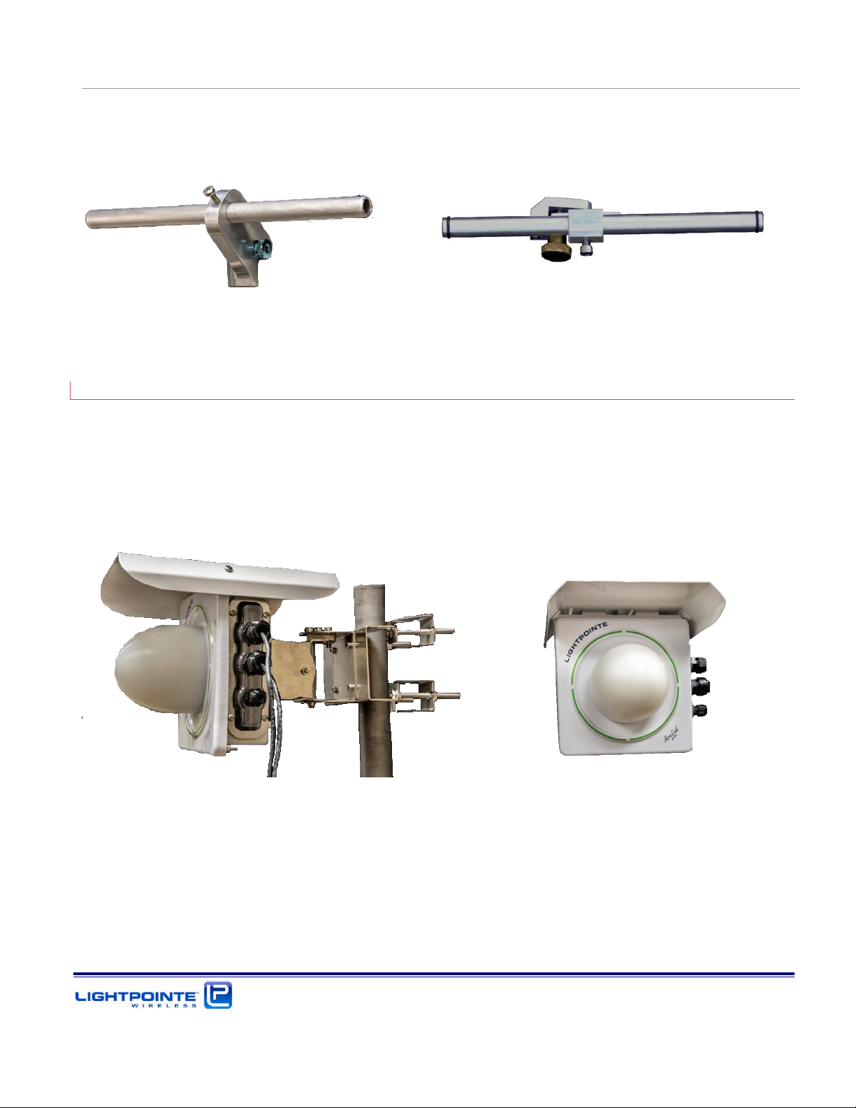
1.2.3 External Antennas and Mounting Brackets
Depending on the system ordered, the AireLink™ 60is shipped either with a high performance high
gain 12” or 24” parabolic Cassegrain antenna. The mounting and alignment bracket is the same for
both antennas. Fig. 1-7 shows the 12” (top) and 24” (bottom) system. For illustrative purposes the
systems are shown with and without the ODU attached.
Figure 1-7: AireLink™60 with one foot (top) and two foot (bottom) antennas attached.
The antenna is equipped with a robust side pole mounting and alignment bracket. The bracket easily
attaches to a vertical structure with pole diameters from 2.5…4.0 inches (65…110 mm). The pole
mounted alignment bracket is shown in Fig. 1-8. Also shown are the locations of the horizontal and
vertical alignment screws.
Figure 1-8: Alignment bracket and locations of alignment screws
Page 23
AireLink 60 Installation and User Manual Rev. D
Introduction
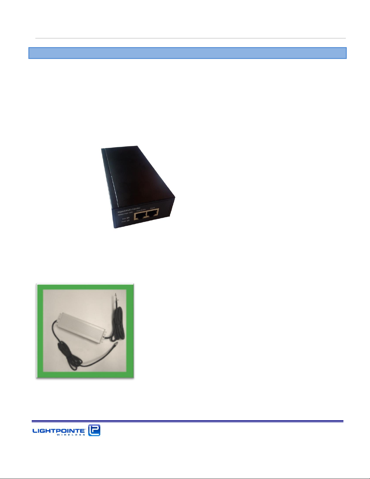
1.2.4 Power over Ethernet (PoE) Modules
The AireLink™ 60 system ships standard with two Power over Ethernet (PoE) injectors for powering
the transmission units. The power provided to the AireLink™ 60 unit travels over a separate
CAT5E/CAT6 cable as the network data but shares a cable with the out-of-band management
connection. The PoE modules accept universal 90-240 Vac input and provide 48Vdc to the AireLink™
60 units. The port labeled Output on the PoE should be connected to the RJ-45 port labeled
Management/PoE on the AireLink™ 60 unit. The port labeled Input on the PoE injector can be connected
to your management network to enable out-of-band system management. The PoE injector is shown
in Fig. 1.9 below.
Figure 1-9: Power over Ethernet modules
In case the customer orders the system with the dc power option rather than the standard PoE supplies,
the PoE injectors will be replaced with a dc power supply (Figure 1-10 below).
Figure 1-10: Optional dc power supply
Page 24
AireLink 60 Installation and User Manual Rev. D
Introduction
1.2.5 Miscellaneous
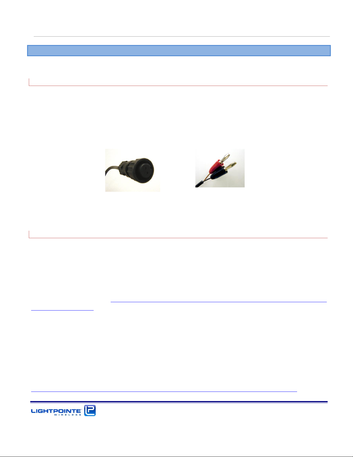
1.2.5.1 RSSI Alignment Cables
A digital voltmeter is used to measure the RSSI voltage changes of the receive signal level during
alignment. Two cables, one for each AireLink™ 60 radio unit, are provided with the shipment. The
cables are terminated on one side with a 2-pin female connector for attachment to the AireLink™ 60
waterproofed IP67 RSSI voltage connector located at the side of the radio enclosure. At the opposite
side the cable has banana plug connectors for attachment to a digital voltmeter (see Fig. 1-11).
Figure 1-11: RSSI alignment cables
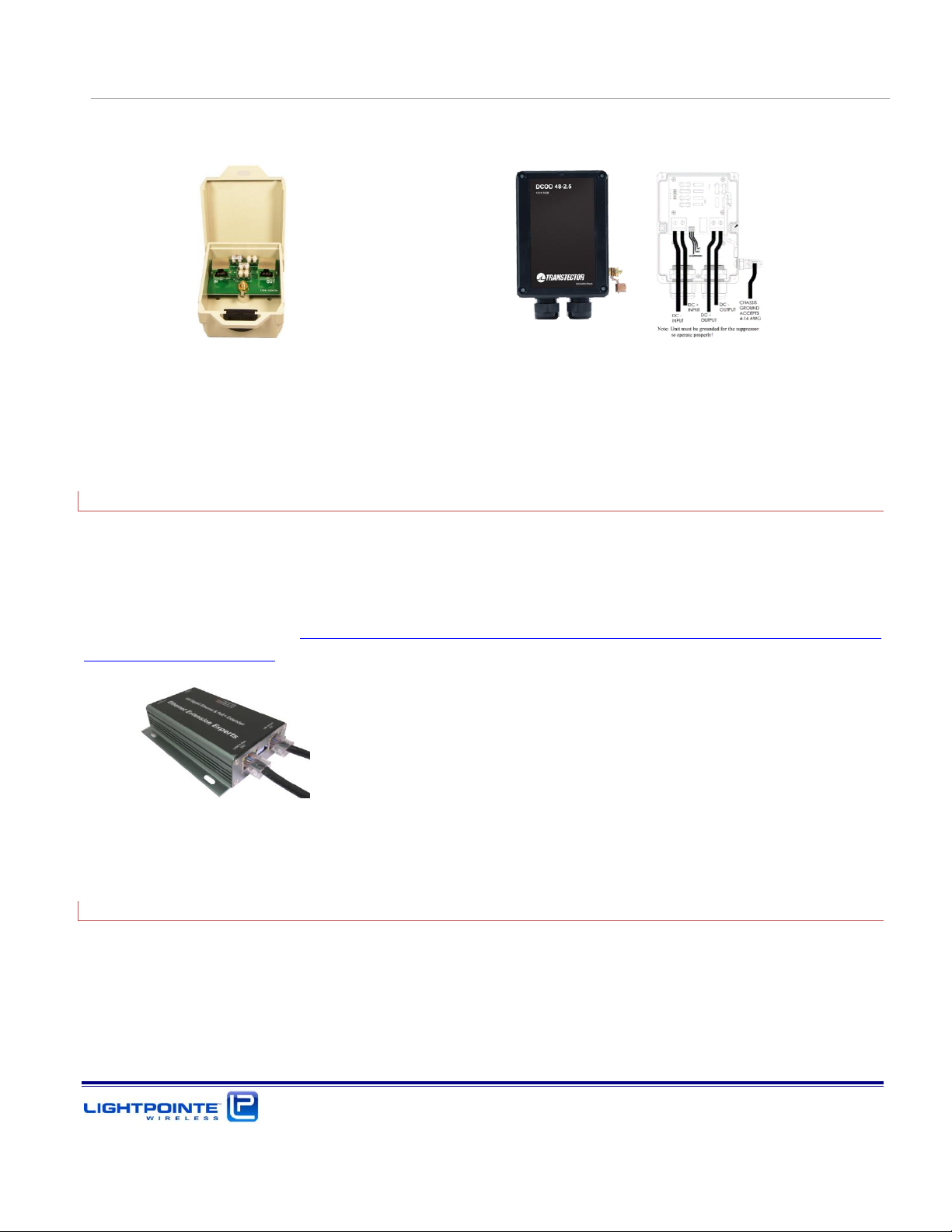
1.2.5.2 Lightning/ Surge Protection
When using the PoE powering/management option and/or the copper data port rather than the fiber
data port option, we strongly recommend using a surge protector to protect networking equipment
attached to the radio to suffer from potential lightning strikes. In case of the PoE/management port, a
10/100 Mbps solution with built in PoE power protection will be sufficient. To protect the 1000 Mbps
copper data port connection, a GbE capable surge protector solution must be used. Figure 1-14 (left)
below shows examples of Ethernet surge protector in an outdoor rated and weather resistant enclosure
made by Enable-IT http://www.ethernetextender.com/ethernet-extension-products/lightning-
protection/265LP.php.
The device in the left of Figure 1-12 is an outdoor rated GbE and PoE+ capable Ethernet lightning/surge
protector (LightPointe part number LM-SURGE-1). LightPointe recommend to install a lightning/surge
protector close to the AireLink radio head to prevent damage to the indoor networking equipment that
is connected to the radio head via CAT5/6 copper cable.
In case the direct two wire 48 Vdc powering option is used, we also strongly recommend using a surge
protector to prevent potential lightning strike surges to enter the in-building power plant. The device
on the right in Figure 1-12 is a 48 Vdc surge protector made by Transtector (Transtector DCOD 48-2.5)
http://www.smithspower.com/brands/transtector/products/dc-surge-protection/1101-1025
Page 25
AireLink 60 Installation and User Manual Rev. D
Introduction
CAT5/6 Ethernet Cable Surge Protectors 48 Vdc Powerline Surge Protector
Figure 1-12: Surge Protectors
1.2.5.3 Optional: Ethernet Cable Extender
When using the PoE powering/management port, the CAT 5/6 Ethernet cable distance between the
networking switch/PoE injector and radio link is limited to 300 feet. Although this is plenty for most
installations there are cases where it is necessary to extent the cable length. This can be accomplished
by using an Ethernet Extender. The device show in Figure 1-13 below can extend the cable run to
distances up to 2000 feet. http://www.ethernetextender.com/ethernet-extension-products/ethernet-
extension-kits/828p.php Please, ask LightPointe customer support for more detailed information.
Figure 1-13: Ethernet Cable Length Extender
1.2.5.4 Optional: Antenna Alignment Tool
To ease the alignment of the narrow beam external antennas, LightPointe can provide a simple
alignment tool (see Figure 1-14) to correctly aim the antenna beam towards the remote antenna site.
The tool works very similar but it is different for the integrated and the externals antennas. In particular
when aligning the longer range 2 foot antenna and or when installing the antennas on a tower, this
tool will reduce the time it takes to get the antennas aligned correctly. The alignment tool is attached
to the ODU /antenna mount and can be easily removed after the alignment process is completed. It
Page 26
AireLink 60 Installation and User Manual Rev. D
Introduction
can therefore be easily re-used when multiple antennas need to be aligned. The function, installation
and use of the alignment tool will be explained in detail in Chapter 4.
Figure 1-14: Alignment Tool for integrated (left) and external Antenna (right)
1.2.5.5 Optional: Weather shield for SX model
When systems are installed in environments that observe a lot of snowfall or in desert like climates
that experience a lot of heat, we recommend installing a weather shield to cover the housing as well
as the lens antenna. The kit includes all nuts and bolts to attach the weather shield to the enclosure
and it can be reactively installed at a later point in time. The AireLink 60 SX with weather shield
installed in shown in Figure 1-15.
Figure 1-15: Side and front view of AireLink 60-SX with optional weather shield installed.
Page 27

AireLink 60 Installation and User Manual Rev. D
Introduction
Page 28

AireLink 60 Installation and User Manual Rev. D
Surveying the Installation Site
2 SURVEYING THE INSTALLATION SITE
Chapter 2 educates the user on millimeter wave transmission technology and the site survey/review
process used in successful deployment of LightPointe AireLink™ 60 systems. Please read this chapter
before installing the system.
2.1 TOOLS
Please ensure that the following measures have been taken and that tools are available for surveying
the installation site.
Have permission of building owner to install the system
Ensure that the installation meets any local requirements
Use an accurately scaled map for locating sites and doing rough distance calculations
Laser range finder or GPS for accurate distance measurement (optional)
Binoculars to assist in locating opposite-end installation site
Sketch or notepad to make rough drawings and notes
Tape measure to determine approximate distance of fiber, power runs, etc.
Camera to take pictures of the installation sites (optional)
2.2 INSTALLATION SITE REVIEW
When performing a site review certain measures must be taken to ensure the successful deployment
of a millimeter wave transmission system.
Determine the appropriate system to meet the needs of each specific location:
Measure point-to-point distance using a map, a laser range finder or GPS coordinates
Refer to the ITU rain zone chart and locate the ITU rain zone where the system will be installed
Determine what physical connections will be required (e.g. SM/MM fiber or CAT5E/6 copper
cable, PoE or direct 48 Vdc)
Determine line-of-sight
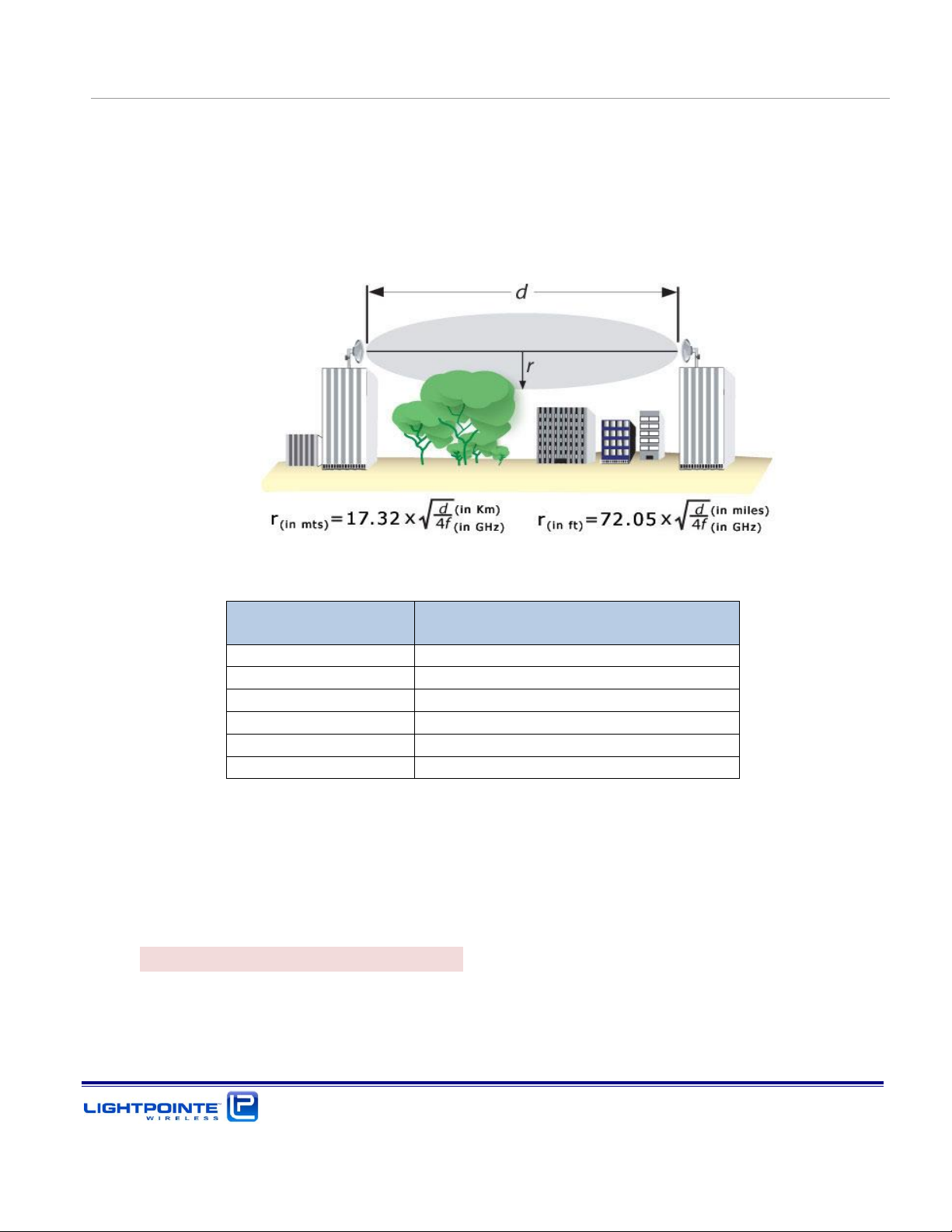
Ensure that the antenna has sufficient path clearance. The Fresnel Zone is the area around the visual
line-of-sight that radio waves spread out into after they leave the antenna (see Figure 2-1). To
maintain good signal strength is important to maintain sufficient path clearance. Typically, a 20%
Fresnel Zone blockage introduces little signal. However, nearing 40% blockage the signal loss will
become significant.
Page 29
AireLink 60 Installation and User Manual Rev. D
Surveying the Installation Site
Path length in meters
Path clearance radius r in meters
100
0.35
200
0.50
500
0.79
1000
1.12
1500
1.37
2000
1.58
The Fresnel Zone formula shown below is based on a flat earth. In other words, it does not take
the curvature of the earth into consideration. The effect of this is to budge the earth in the
middle of the link. However, for relatively short distances, the effect of the earth’s curvature
and the specific topography of the terrain are negligible.
Table 2-1 shows the calculated minimum path clearance required for operation of a pt-to-pt
millimeter wave operating in the 60 GHz band based on the Fresnel Zone formula shown below.
Figure 2-1: Fresnel Zone illustration.
Table 2-1 Fresnel zone path clearance
Can emissions, blowing or swaying trees, or other obstacles in the line of sight interrupt the
connection?
Is there a possibility of work activity or people passing in front of the transmission that could
interfere with the clear line of sight
Evaluate environmental mounting conditions
Only mount the radio transmission equipment to a stable and vibration-free mounting platform
– this is a critical factor to successful performance.
Page 30
 Loading...