

Lightonics FXLD2512B516 Owner's Manual
PIN #
SIGNAL NAME
1
DMX COMMON
2
DMX DATA -
3
DMX DATA +
CAUTION
RISK OF ELECTRIC SHOCK
Page 1 of 6
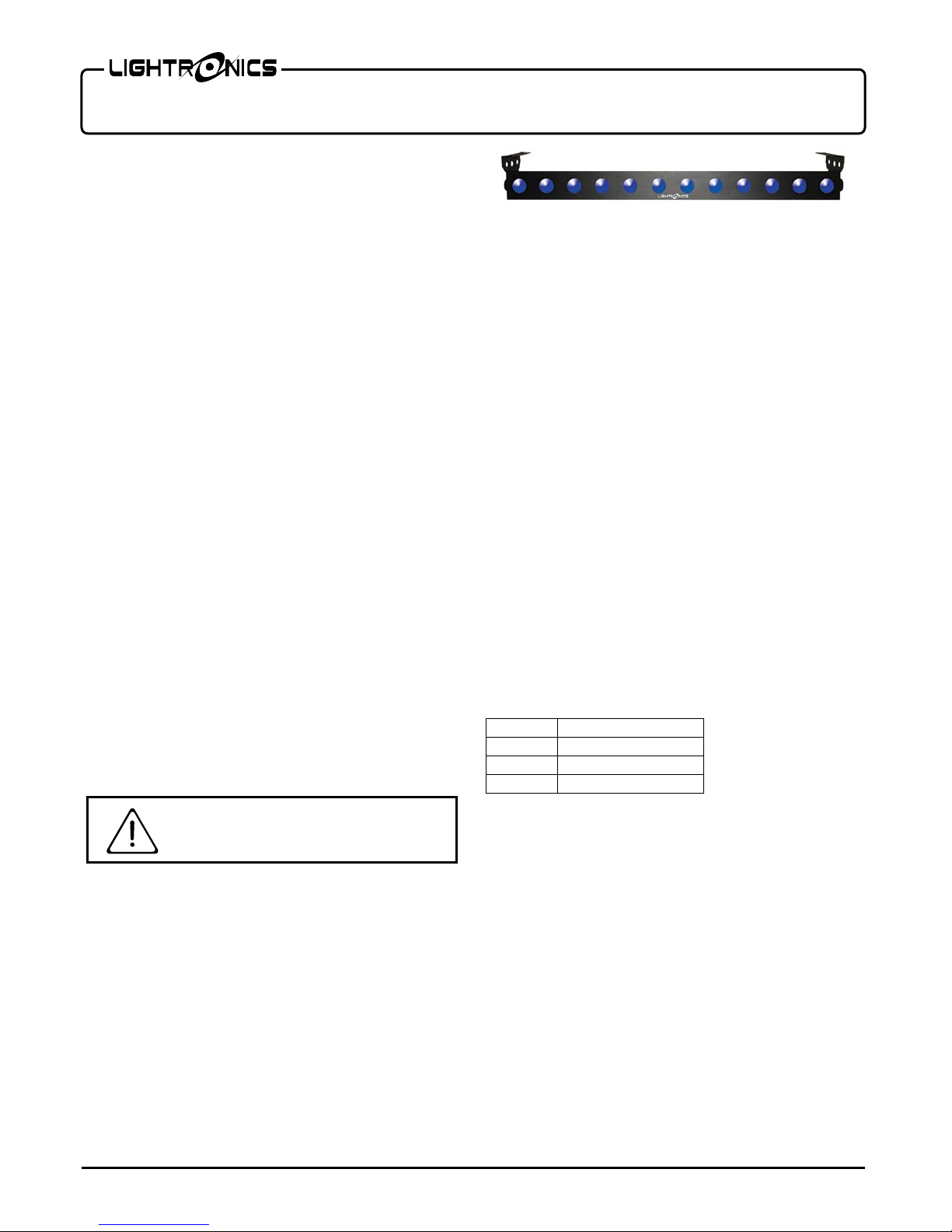
FXLD2512B516 LED FIXTURE
Version 0.2 OWNERS MANUAL 09/14/17
FEATURES AND SPECIFICATIONS
LEDS: 12, 25W each (RGBWA, 5in1)
Beam angle: 60ᵒ
Control system: DMX512 + Stand Alone Modes
DMX channels: 5/9
DMX connectors: 3 pin XLR I/O
Refresh Rate: >3000 Hz)
Voltage: 100 - 240 VAC 50/60Hz
Max power consumption: 330 Watts
Cooling: Internal Fan
Body material: Sheet steel
Body color: Black
Size: 39.4"L x 5"W x 3.4"H
DESCRIPTION
The FXLD2512B516 is a RGBWA LED li ghting fixture. I t
is suitable for stage, disco, night club, and other artistic
applications. It has several stand-alone control modes and
can operate via a DMX512 external s ignal.
INSTALLATION
LOCATION
The FXLD2512B516 is rated IP20 and is intended for
INDOOR USE ONLY.
Locate the unit in a well ventilated area away from moisture
and heat. Keep the vent holes clear. Holes are provided on
the brackets to install a lighting bar p ipe cla mp. Use a safety
cable when hangi ng t he fi xt ur e .
POWER CONNECTIONS
The FXLD2512B516 has a blue turn and lo ck connecto r for
power input. A compatible power cable is provided for
connection to a 120 VAC, 15 Amp, 60Hz, grounded service.
Push the blue connector on the cable straight into the blue
connector on the unit and twist approx. 1/8 turn clockwise to
latch it. The white turn and lock connector on the unit is
used to pass power on to another FXLD2512B516 unit. A
mating white connector is also provided.
Caution is advised since the line cord is rated for approx. 7
Amps maximu m.
THE SAFETY GROUND TERMINAL ON THE POWER
CABLE MUST BE USED.
DMX CONNECTIONS
A sys tem usin g DMX cont rol must be connected as a chain
of devices. In other words the control signal cable should
proceed from the controller to the first receiving device and
then to others in a continuous "d aisy chain" fas hi on.
The fixture ha s a DMX IN and a DMX OUT connector to be
used to connect the chain. The control cable should NOT be
split into a multiple run star arrangement with a cable
running from the controller directly to each receiving device
pack.
DMX CONNECTOR PIN ASSIGNMENTS
There are two different connectors which can be used for
DMX control. They are both XLR type connectors.
This unit uses 3 pin XLR type connectors. The
FXLD2512B516 receives a DMX signal on the 3 pin MALE
connector on one side of the unit.
3 Pin Pinout
DMX TERMIN ATION
A DMX chain should be terminated at the last receiving
device on the c hain. Thi s is done b y installin g a commonl y
available 1/4 Watt, 120 O hm r esistor a cro ss the D ATA - and
DATA + wires at the last device. If you have only a few
fixtures very close together and a very short run to the
controller then you may be able to operate without the
terminator.
www.lightronics.com
Lightronics Inc. 509 Central Drive Virginia Beach, VA 23454 757 486 3588

MENU
UP
DOWN
ENTER
CONTROL PANEL
Page 2 of 6
FXLD2512B516 LED FIXTURE
Version 0.2 OWNERS MANUAL 09/14/17
OPERATION
A control panel on the back of the unit is used to set the
operating options. It consists of an LED display and four
buttons (MENU, UP, DOWN, and ENTER)
Push MENU to access the operating options. Press UP or
DOWN to cycle through options. When you reach the
option you want to set or cha nge use the ENT ER button to
select the option to change. Then use the UP and DOWN
buttons to modify the values. Push ENTER to save your
changes and deactivate the option. See the "MENU
NAVIGATION" diagra m for add itional details.
There are 9 operation modes: DMX 5 channel, DMX 9
channel, Color Fade, Color Change, Color Select, Manual
Level (5 selections), Demo, Sound, delo.
DMX OPERATION
For DMX operation the FXLD2512B516 fixture can be
configured as a 5 channel or 9 c hannel unit.
Use the dXXX (5 ch) or AXXX (9 ch) menu to set the
starting address of the unit. You can select the starting
address o f t he unit with the UP and DOWN buttons.
Detailed information on DMX chan nel operation is given in
the tables DMX VALUES AND FUNCTIONS.
MANUAL OPERATION
Color Select (CSXX)
For additional manual operations you can use the Color
Select menu (CSXX) to select a color and level.
Color Change (CCXX)
The color change mode cycles through a variety of colors at
a user defined speed. Use the CCXX menu to set the rate o f
speed at which the co lors change. The r ange is from 01 to
99. 99 is fastest and 01 is slowest.
COLOR FADE (CFXX)
The Color Fade mode cycles smoothly through a sequence
of colors. Use the CFXX menu to set the speed and activate
the option. The range is from 1 to 99. 99 is fastest.
R, G, B, W, A MANUAL LEVEL CONTROL
You can operate the individual color levels manually using
the r.000, g.000, b.000, E.000, and Y.000 menus. Use t he
UP and DOWN buttons to change the level, Push ENTER
when done. The range is 000 - 255 (255 is maximum).
DEMO MODE (dENo)
This option is currently not ope r a ble with this unit.
SOUND MODE (Soun)
The unit reacts to sounds by changing colors randomly.
There are no other settings within this mode.
DELAY MODE (dELO)
Option not supported at this time.
www.lightronics.com
Lightronics Inc. 509 Central Drive Virginia Beach, VA 23454 757 486 3588
 Loading...