

Page 1
Architectural Decorative IS:CCLPS602P
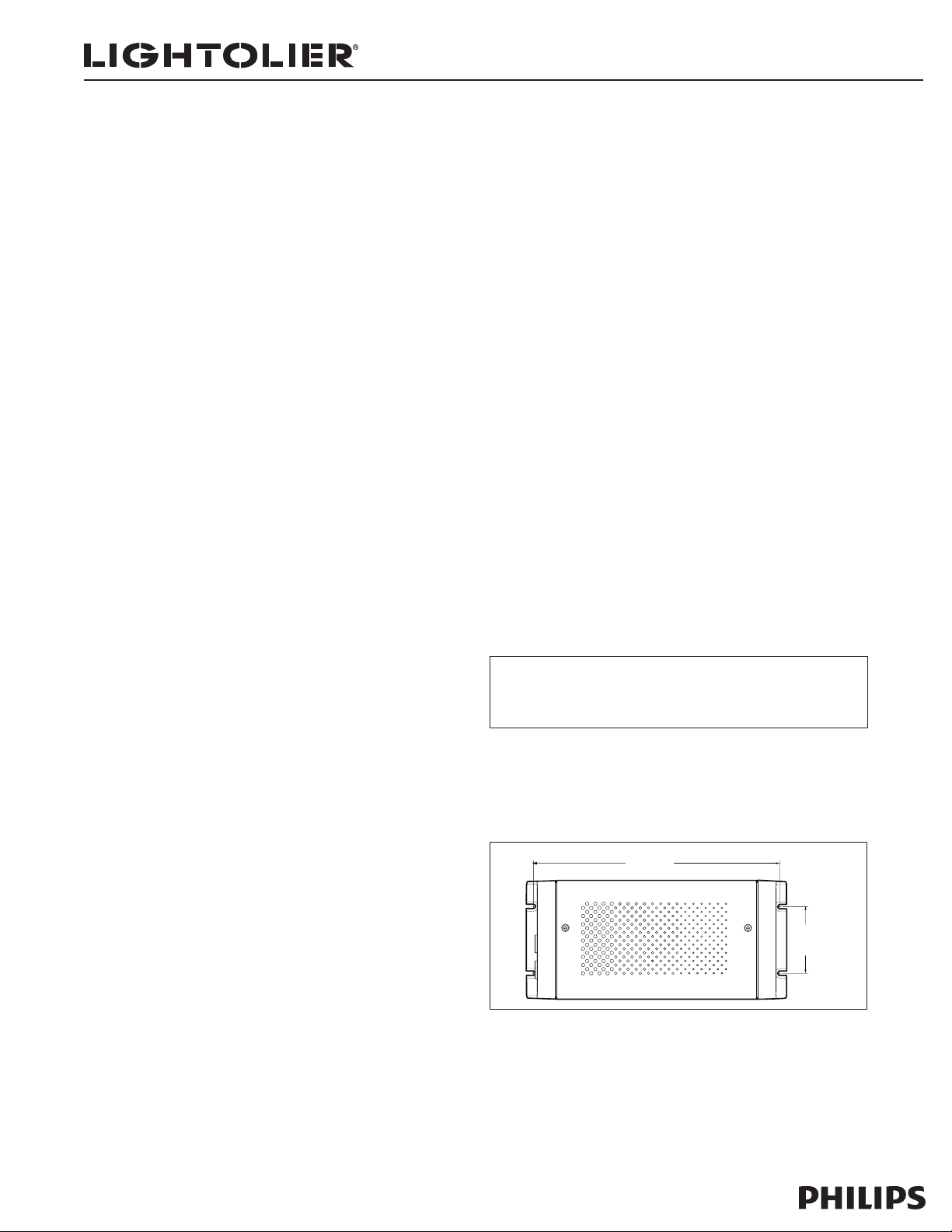
(21.2 cm)
8.31"
(5.7 cm)
2.25"
Fig. 1
Page 1 of 4 Instruction Sheet for Assembly and Installation
Read and understand these instructions before installing luminaire
This luminaire is intended for installation in accordance with the National Electrical Code and local regulations. To assure full compliance with local codes and
regulations, check with your local electrical inspector before installation. To prevent electrical shock, turn off electricity at fuse box before proceeding.
Retain these instructions for maintenance reference.
Getting Started
CCLPS602P is a compact power/data supply for indoor installations. CCLPS602P
provides power and data to Lightolier concealed color lighting product lines, and
is available for DMX and Ethernet control options.
The “s” type of power supply provides additional features, such as base address
and grouping of luminaire addresses, without the need for external components.
This instruction guide contains important information on installing and using your
new CCLPS602P. Please read it carefully and save it for future reference.
Included In This Box
• Power/data supply
• US Grounded IEC Power Cord Set
• RJ-45 Terminator
• Instruction Sheet
Additional Items Needed
• Mounting hardware – 4 flat head screws M3.5 or #6
Scope of this Instruction Guide
The goal of this user guide is to explain the steps necessar y to install
CCLPS602P for DMX and Ethernet control to assure peak performance. Its
intended use is for reference only, by persons who are fully qualified. This document should never be considered a substitute for any provisions of a regulation
or state and/or local code.
Identification and Warnings of Safety Hazards
In accordance with ANSI Z535.4-2002, the following system identifies the severity of the hazards associated with the products:
“Danger” Imminently hazardous situation which, if not avoided, will result in
death or serious injur y.
“Warning” Potentially hazardous situation which, if not avoided, could result in
death or serious injur y.
“Caution” Potentially hazardous situation which, if not avoided, may result
in minor or moderate injury or property damage. Also used to alert
against unsafe practices.
Ignoring a hazard will void any warrant y.
Warning: Ensure that power is disconnected before installing, wiring, or servic-
ing the CCLPS602P power supply.
Warning: The CCLPS602P power supply must be installed by a qualified profes-
sional in accordance with NEC and relevant local codes.
Warning: Do not at tempt to install or use CCLPS602P until you read and under-
stand the installation instructions and safety labels.
Warning: Do not use CCLPS602P if power cables are damaged.
Warning: This equipment has been tested and found to comply with the limits
for a Class A digital device, pursuant to part 15 of the FCC Rules. This equipment
generates, uses, and can radiate radio frequency energy and, if not installed and
used in accordance with the instruction manual, may cause harmful interference
to radio communications. Operation of this equipment in a residential area is
likely to cause harmful interference in which case the user will be required to
take adequate measures.
Caution: Ensure that CCLPS602P is securely at tached, properly mounted, and
free of excessive vibration.
Caution: Do not hot swap. Ensure the power supply is off before connecting or
disconnecting luminaires.
Caution: Do not modify or alter CCLPS602P.
Note: The instructions and precautions set forth in this installation guide are
not necessarily all-inclusive or relevant to all applications as Lightolier cannot
anticipate all conceivable or unique situations.
Owner/User Responsibilities:
It is the responsibilit y of the contractor, installer, purchaser, owner, and user to
install, maintain, and operate CCLPS602P in such a manner as to comply with
all state and local laws, ordinances, regulations, and the American National
Standards Institute Safety Code.
Note: CCLPS602P is shipped with a US IEC power cord. For international customers, use a country-specific IEC cable meeting the following specifications:
3-conductor, 18AWG (1.00mm2), HAR rating for Europe, and JET rating for Japan.
(Hard Service Type ST or equivalent.)
Note: Ensure the IEC inlet plug fits in the supplied lock. The lock may not accommodate all plug styles.
Installation:
CCLPS602P must be installed by a qualified electrician in accordance with NEC
and relevant local codes for power supplies. A power screwdriver is recommended for mounting the unit.
Mounting the Housing
• Select the location to mount the housing, keeping CCLPS602P within the
maximum distance specified for your luminaire. Refer to your luminaire user
guide for the cable run information.
Caution: CCLPS602P must be installed in a location that allows air to move
freely. Packing insulation around the housing or mounting in a sealed location
that raises ambient temperature above 122°F (50°C) may result in property damage and may void the warranty.
Note: Ensure that there is adequate space to make all connections to the front
and rear of the unit.
• Mount the housing to a flat surface using four M3.5 or #6 flat head screws
suitable for the mounting surface. Mounting slots are located on each end of
the housing. (See Fig. 1.)
Note: Do not overtighten the mounting screws.
Lightolier is a Philips group brand
631 Airport Road, Fall River, MA 02720 • (508) 679-8131 • Fax (508) 674-4710
We reserve the right to change details of design, materials and finish.
www.lightolier.com © 2008 Philips Group • A0908
Page 2
Architectural Decorative IS:CCLPS602P
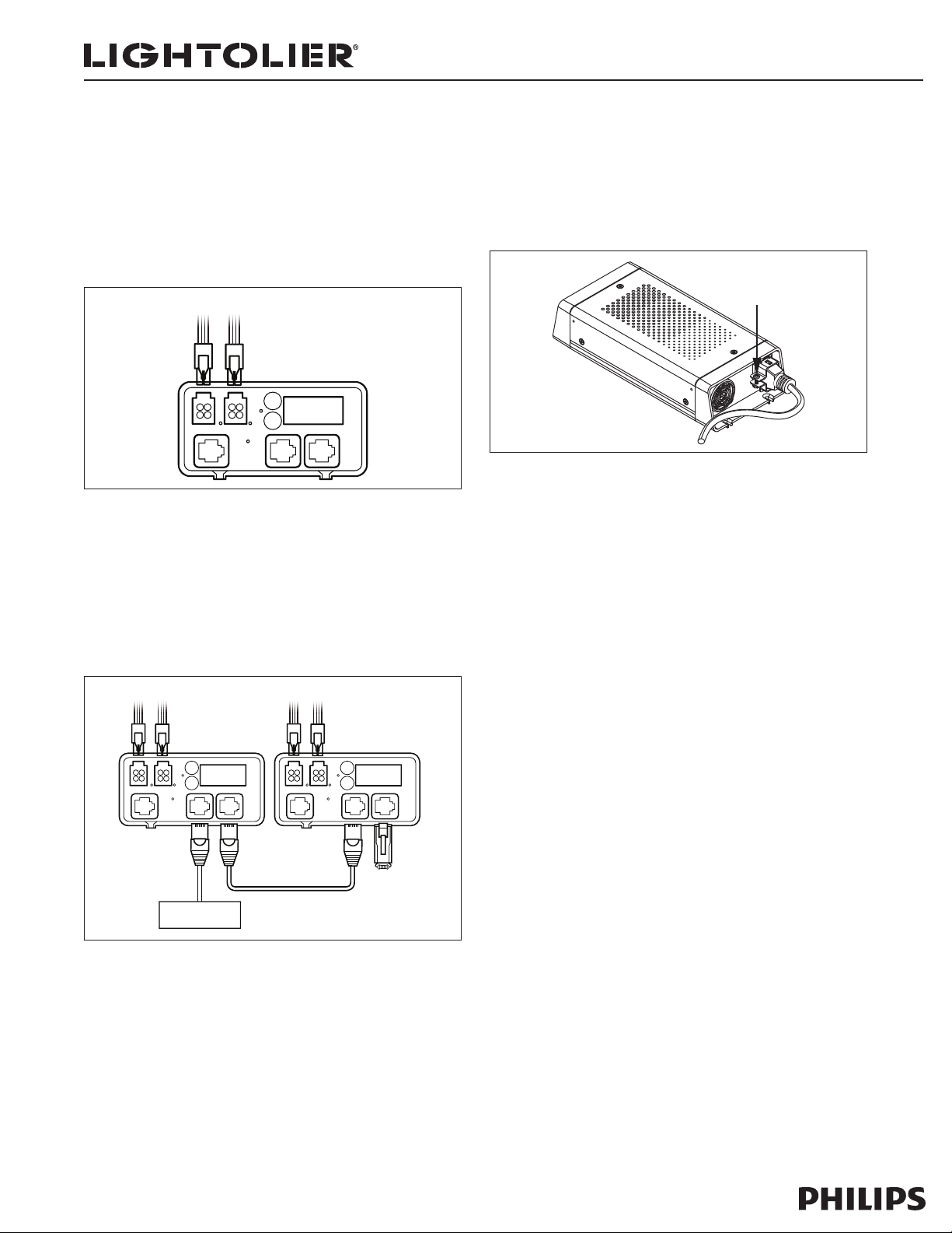
OUT 1
OUT 2
ENET IN
DMX IN
DMX OUT
To Luminaires
Fig. 2
OUT 1
OUT 2
ENET IN
DMX IN
DMX OUT
To Luminaires To Luminaires
OUT 1
OUT 2
ENET IN
DMX IN
DMX OUT
DMX IN DMX OUT DMX IN Terminator
Lightolier® DMX or
Color Rotary Dial Controller
Fig. 3
Tighten Screw
To Lock
Fig. 5
Page 2 of 4 Instruction Sheet for Assembly and Installation
Wiring:
After mounting the power/data supply, you are ready to connect power, luminaires, and data to CCLPS602P.
Connecting Luminaires to CCLPS602P
• Plug the leader cable connector into a power output receptacle on the front
of CCLPS602P. Power outputs are labeled Out 1 and Out 2. (See Fig. 2.)
Note: When using one luminaire run per CCLPS602P, use Output 1.
• Refer to the user guide for your luminaires to determine maximum number of
luminaires per power/data supply and specific wiring requirements.
Connecting DMX Data:
CCLPS602P receives DMX data from, and can be controlled by, Lightolier’s full
line of DMX512 controllers or any third party DMX512 controller.
• Plug the data RJ-45 connector from the controller into the DMX IN por t.
• To daisy-chain DMX data to another CCLPS602P, connect a CAT5 cable with
RJ-45 connectors between the DMX OUT port of the first unit and the DMX
IN por t of the next unit. Plug a terminator into the DMX OUT port of the last
power supply in a data chain. (See Fig. 3.)
Connecting Power:
• Connect the IEC power cable to the back of unit. Plug the IEC power cable
into a standard 100-240VAC outlet. Tighten the screw to secure the clamp.
(See Fig. 5.)
Note: If power supply does not power up (front display is blank) make certain
power cable is firmly inser ted into the receptacle on the back of the unit.
Lightolier is a Philips group brand
631 Airport Road, Fall River, MA 02720 • (508) 679-8131 • Fax (508) 674-4710
We reserve the right to change details of design, materials and finish.
www.lightolier.com © 2008 Philips Group • A0908
Page 3

Architectural Decorative IS:CCLPS602P
3-Digit Display
UP
DOWN
Fig. 6
CONFIGURATION MODE
Fig. 7
OUTPUT NUMBER OF LIGHTS
EXAMPLE: 13 LIGHTS ON OUTPUT 2
Fig. 8
Page 3 of 4 Instruction Sheet for Assembly and Installation
Addressing the Luminaires
When using the DMX control input, you are required to set the base address for
the unit and configure the luminaires connected to it.
The base address for the supply will be the starting address for the first
luminaire connected to Output 1. You can also group more than one luminaire
to the same address or reverse the addressing sequence of the luminaires on
Output 1.
Setting Base Addresses
1. Press and release the UP or DOWN address buttons to step through the base
address. The address numbers 1 through 170 will appear in the display. Press
and hold either button to rapidly advance to the desired luminaire number.
Stop when the desired base number appears on the display. (See Fig. 6.)
2. After selecting a base address, press and hold the UP and DOWN buttons
simultaneously to enter configuration mode. "CFG" appears in the display.
(See Fig. 7.)
When entering Configuration mode, the unit automatically discovers all lumi-
naires that are connected and addresses them sequentially, beginning with
the base address on the first luminaire on Output 1 through the last luminaire
on Output 2. This step ensures that the unit correctly identifies all of the
luminaires connected to its outputs.
After the discovery is complete, two 3-digit numbers are briefly displayed.
The first digit indicates the output port and the last two digits denote the
number of luminaires connected to that output. For example, the number 107
represents 7 luminaires on Output 1, while the number 213 indicates 13 luminaires on Output 2. If there are no luminaires at tached to an output, the last
two digits are 00, as in 200. (See Fig. 8.)
3. To exit Configuration mode, press both but tons simultaneously. The base
address for the unit will appear on the display.
Grouping Luminaire Addresses
CCLPS602P allows you to conserve the total number of luminaire addresses in an
installation by grouping luminaires together. When you group luminaire addresses, you can assign multiple luminaires to the same address. The number of luminaires per group is limited to the maximum number of luminaires connected to
Output 1. (For example, if you have 10 luminaires connected to Output 1 and 12
luminaires connected to Output 2, the maximum group number is 10.)
To set grouping of luminaire addresses:
1. Press and hold the UP and DOWN buttons simultaneously to enter configura-
tion mode. “CFG” appears in the display.
2. When entering Configuration mode, CCLPS602P automatically discovers all
luminaires that are connected.
3. Use the UP button to set a positive group number (the number of luminaires
per group), according to the following table.
Group
How Luminaires Are Addressed
Address
ALL ALL luminaires are assigned the selected Base Address.
1 All luminaires are addressed sequentially, starting with the Base
2 Every two luminaires are assigned the same address. For example, if
3 Every three luminaires are assigned the same address. For example, if
4 to 20 ...
If you have 20 luminaires with a Base Address of 1, they are addressed as follows:
Light #: 1 2 3 4 5 6 7 8 ... 18 19 20
Address: 1 1 1 1 1 1 1 1 ... 1 1 1
Address. If you have 20 luminaires with a Base Address of 1, they are
addressed as follows:
Light #: 1 2 3 4 5 6 7 8 ... 18 19 20
Address: 1 2 3 4 5 6 7 8 ... 18 19 20
you have 20 luminaires with a Base Address of 1, they are addressed
as follows:
Light #: 1 2 3 4 5 6 7 8 ... 18 19 20
Address: 1 1 2 2 3 3 4 4 ... 9 10 10
you have 20 luminaires with a Base Address of 1, they are addressed
as follows:
Light #: 1 2 3 4 5 6 7 8 ... 18 19 20
Address: 1 1 1 2 2 2 3 3 ... 6 7 7
Note: It is recommended that you set your group number to a number that
evenly divides the number of luminaires connected to Output 1 and you balance
the number of luminaires on each output. Otherwise, you may have a smaller
amount of luminaires at the end of each output port that would receive the next
address.
4. Use the DOWN button to set reverse addressing.
Note: CCLPS602P allows you to reverse the addressing sequence on Output
1 ONLY.
Using reverse addressing, the last luminaire on Output 1 receives the Base
Address, and then the addresses are assigned sequentially from the last
luminaire to the first.
Reverse addressing is particularly useful if you mount your power supply in
the center of a linear feed or if you want to feed an installation that uses
multiple power supplies from each side. Use reverse addressing to chase
from one end of the luminaire run to the next. (See Fig. 9 for examples.)
Use the DOWN button to set a "negative" group number, according to the fol-
lowing table. Set a negative group number to use reverse addressing.
Lightolier is a Philips group brand
631 Airport Road, Fall River, MA 02720 • (508) 679-8131 • Fax (508) 674-4710
We reserve the right to change details of design, materials and finish.
www.lightolier.com © 2008 Philips Group • A0908
Page 4

Architectural Decorative IS:CCLPS602P
OUT 1
OUT 2
ENET IN
DMX IN
DMX OUT
CCLPS602P
(Center Feed Installation)
Base Address = 1
9
210
1
291
20
2 91
0
291
20
Group Address
Set to “-1”
Group Address
Set to “1”
Example 1:
When using a Rainbow Wash with sequential addressing
(group address set to 1), the luminaire flows from the center
(the first luminaire on Output 1) to the last luminaire in Output 1, and
then back to the first luminaire on Output 2.
When using a Rainbow Wash with reverse addressing
(group address set to -1), the luminaire flows from left to
right across all fixtures. The luminaire goes from the last fixture
on Ouput 1 to the first fixture on Output 1, and then to the
first fixture on Output 2 to the last fixture on Output 2.
Examples of Sequential and Reverse Addressing
Note: Reverse addressing only reverses the addresses on Output 1 of the CCLPS602P.
Fig. 9
OUT 1
OUT 2
ENET IN
DMX IN
DMX OUT
OUT 1
OUT 2
ENET IN
DMX IN
DMX OUT
CCLPS602P DMX/Ethernet
(Base Address = 2
1)
CCLPS602P DMX/Ethernet
(Base Address = 1)
202
1
202
1
2240 2
2 39 40
Group Address
Set to “-1”
Group Address
Set to “1”
Group Address
Set to “1”
Group Address
Set to “-1”
Example 2:
Reverse addressing allows you to have a continuous Rainbow Wash
when you have an installation fed by more than one power supply.
When using sequential addressing on both power supplies, the luminaire
flows from the first luminaire on Output 1 of the first power supply to the
last luminaire on Output 1 (left to right), and then it flows from the first
luminaire on Output 1 of the second power supply to the last luminaire on
Output 1 (right to left).
Using reverse addressing on the second power supply allows you to
set up the flow from left to right across all fixtures. With this setup,
the luminaire flows from the first luminaire on Output 1 of the first power supply
to the last luminaire on Output 1, and from the last luminaire on Output 1 of the
second power supply to the first luminaire on Output 1.
Page 4 of 4 Instruction Sheet for Assembly and Installation
Group
How Luminaires Are Addressed
Address
-1 All luminaires are addressed sequentially, starting with the Base
Address. If you have 20 luminaires with a Base Address of 1, they are
addressed as follows:
Light #: 1 2 3 4 5 6 7 8 ... 18 19 20
Address: 20 19 18 17 16 15 14 13 ... 3 2 1
-2 Every two luminaires are assigned the same address. For example, if
you have 20 luminaires with a Base Address of 1, they are addressed
as follows:
Light #: 1 2 3 4 5 6 7 8 ... 18 19 20
Address: 10 10 9 9 8 8 7 7 ... 2 1 1
-3 Every three luminaires are assigned the same address. For example,
if you have 20 luminaires with a Base Address of 1, they are addressed as follows:
Light #: 1 2 3 4 5 6 7 8 ... 18 19 20
Address: 7 7 6 6 6 5 5 5 ... 1 1 1
-4 to -20 ...
Note: It is recommended that you set your group number to a number that
evenly divides the number of luminaires connected to Output 1 and you
balance the number of luminaires on each output. Otherwise, you may have
a smaller amount of luminaires at the end of each output port that would
receive the next address.
5. To exit Configuration mode, press both buttons simultaneously. The base
address for CCLPS602P will appear on the display.
CCLPS602P Specifications
Power Input 100 -240VAC, 50Hz–60Hz, 1.1-0.4A
Power Output 24VDC (62W Max.)
Heat Dissipation 22% of total power input at maximum load
Ambient Operating Temp 14°F to 122°F (-10°C to 50°C)
Housing 8.8” (22.4 cm) X 4.0” (10.2 cm) X
2.0” (5.1 cm)
Weight: 2.0 lbs (907 g)
Connectors Data: RJ45 input and output connectors
Power: 4-pin output connectors, IEC power con-
nector (Supplied with C13 IEC plug, grounded US
outlet plug. UL/CSA rated 18 AWG 3/C ST 90°C
Rated.)
Data Input Interface Lightolier Lytemode DMX, color rotary dial or
DMX 512 compatible controllers.
Data Output Inter face 24V
Classification Class 2
Listings UL/cUL, CE, PSE
Max. # of Luminaires 12": 20; 6": 36
Lightolier is a Philips group brand
631 Airport Road, Fall River, MA 02720 • (508) 679-8131 • Fax (508) 674-4710
We reserve the right to change details of design, materials and finish.
www.lightolier.com © 2008 Philips Group • A0908
 Loading...