

Page 1

READ AND UNDERSTAND THESE INSTRUCTIONS BEFORE INSTALLING TRACK
This fixture is intended for installation in accordance with the National Electrical Code and local or Federal code
specifications. To assure full compliance with codes and regulations, check with your local electrical inspector
before installation. To prevent electric shock, turn off electricity at fuse box before proceeding.
and refer to them when additions to or changes in the track configuration are made.
Save these instructions for maintenance reference
Installation Instructions for ProSpec™ Track Lighting--
Recessed Feed Track and Plain Track Units.
ProSpec™ track lighting is designed to support and energize ProSpec™ Lytespots® which can be
attached anywhere along the track. It is a four conductor system, continuously grounded throughout, to be supplied by two single 120V, 20 amp, 60Hz branch circuits. It is not intended for use with
a power cord or convenience receptacles. ProSpec™ is listed by Underwriters Laboratories, Inc. It
may only be used with electrical fittings identified for use with ProSpec™ track.
IMPORTANT SAFETY INSTRUCTIONS
Read all Track, Connector, Feed-in Kits, and Accessory Instruction Sheets before
installing any ProSpec
safety precautions should be followed:
™ Track item. When installing or using this track system, basic
INSTRUCTION SHEET NO.
IS:26600
A0397 Page 1 of 4
Read all instructions before installing the track system.
• Do not install in wet media (concrete, plaster, etc.).
• This track system is intended for installation in accordance with the National
Electrical Code and Local or Federal Codes.
• Do not install this track in wet or damp locations.
• Do not install any part of this track system less than 5 feet above floor.
• Do not install any fixture assembly closer than 6 inches from any curtain, or similar
combustible material.
• To prevent electrical shock, turn off electricity at fuse box before installing the track
or adding to or changing the configuration of the track.
• Instructions for grounding per instruction sheet of the feed-in kit used must be
followed. Failure to do so may result in a hazardous condition.
• Use #12 ga. AWG solid wire only (not stranded wire) for supply to track.
• Observe polarity, white supply lead (neutral) to contact marked “NEUT” on screw
terminal connectors.
• Do not exceed 4 feet between mounting points.
• Do not attempt to energize anything other than track lighting fixtures on the track.
To reduce the risk of fire and electrical shock, do not attempt to connect power tools,
extension cords, appliances and the like to the track.
SAVE THESE INSTRUCTIONS
FALL RIVER, MASSACHUSETTS 02720
MONTREAL, QUEBEC, CANADA
Page 2
INSTRUCTION SHEET NO.
IS:26600
A0397 Page 2 of 4
Recessed ProSpec™ Track Mounting Methods
MOUNTING PROSPEC™ TRACK
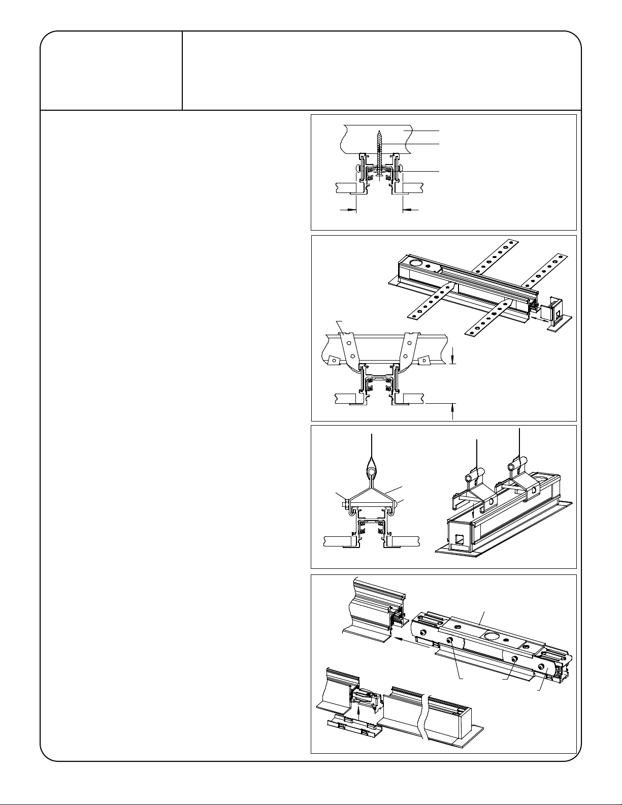
There are three methods of mounting the track to a surface (Fig A, B & C).
1. Direct mounting (Fig A):
•Mark centerline for track location.
•Add mounting holes to the track.
In the center of the track drill the appropriate number of mounting
holes. The holes should be 3/16" in diameter. Recommended: two
holes per 4' track, three holes per 8' track, and four per 12' track.
Never use one mounting hole per track length. Additional holes may
be added for more support. The holes should be evenly spaced along
the track length.
CLEAN ALL METAL AND PLASTIC CHIPS FROM THE TRACK.
•Mount the track to the structure using #6 flat or round head screws,
and plastic washers. Use a screw appropriate for the material. For
example, use a #6 flat head wood screw if you are mounting into a
wood beam. Plastic washers are included; screws are not included.
2. Mounting Straps (Fig. B):
•Mark centerline for track location.
•Remove the Dead End from one end of the track and save.
•Slide the mounting straps into the groove in the side of the track. An
equal number of straps should be on each side of the track. Always
use more then one strap per side.
•Wrap the straps around the building structure or nail the straps to the
structure.
•Push Dead End into the track at the end of the track run.
3. Hanger Clips (sold separately Cat. 26090 set of 4) (Fig. C):
•Slide or snap the hanger clips onto the track.
•Assemble the screws and nuts onto the mounting clips.
•Recommended: two clips per 4' track, three clips per 8' track, and four
per 12' track. Always use more then one clip per track length.
Additional clips may be added for more support. The clips should be
evenly spaced along the track length.
•Tighten the clip on the track by tightening the screw and nut. Pass
cable through hole in hanger clip. Level track and tie cable to support
the track.
FIG. A
FIG. B
Nut
Structural Mounting Material
#6 Screw appropriate to Mounting Material
Plastic Washer
1-7/8"
Ceiling Opening
Mounting Straps
Feed Track
Mounting Straps
Dead End (Remove)
1-1/2"
Hanger Clip
Screw
STRAIGHT CONTINUOUS RUN OF TRACK
•Remove the Dead End from one end of the track that will be joined.
•Slide the spline (1/2 its total length) into the side channels of the track
unit.
•Install the spline screws into the spline and tighten.
•Use an Invisible Coupler (26049WH) to join two tracks together
mechanically and electrically (Fig. D). Power cannot be fed into the
coupler. See the instructions provided with the coupler prior to
installation.
•Use an In-Line connector (26654WH) to feed power between two track
units. Additional splines are not required when using the In-line
Connector. The connector comes with the splines attached (Fig. D).
See instruction sheet provided with the In-line connector prior to
installation.
•Tighten all spline screws.
•Push Dead End into the track at the end of the track run.
FIG. C
FIG. D
Mini Coupler
Track Unit
In-Line Connector
Spline Screws
Spline
Track Unit
Page 3

Instructions for Recessed ProSpec™ Track
Power Feed to Track
DIRECT POWER FEED TO "FEED" TRACK
Use solid 12 ga. copper wire when feeding the track. The feed track accepts
two separate 120 V, 60 Hz branch circuits. Each circuit must not exceed the
20 amp capacity of the track system.
FEED FROM ABOVE TRACK (Fig E):
•Remove Bottom cover and save.
•Remove Knockout in Top Plate.
•Remove Top Plate from Track
•Secure electrical connector (by others;
Plate using the Nut provided. Position connector locking screws such
that the screws will be hidden behind the track width.
•Attach Top Plate to track.
•Pass wires through connector and secure the cable or conduit to the
connector.
The track must not support the cable
for securing the cable to the building structure.
•Secure the track to the ceiling (
•Form the wires in the Feed track to the connector terminals
(see FIG. F). Cut and strip each wire. Attach wires to the screw
terminals. Wires must be tightly held in the screw terminals. Neutral
wires must be attached to screw terminals marked "NEUT”. Ground
wire must be attached to the green ground screw.
•Snap Bottom Cover into the track.
3
/8 size recommended) to Top
. Use separate support
see mounting on previous page
).
Electrical
Connector
Knock out
FIG. E
Circuit 2
Neutral 2
INSTRUCTION SHEET NO.
IS:26600
A0397 Page 3 of 4
Top Plate
Feed Track
Bottom Cover
Use 12 ga. solid copper wire for feed
connections including ground.
Circuit 1
Neutral 1
FEEDING ALONG THE TRACK LENGTH (Fig. G)
A floating splice box may be used to feed the "Feed Track" from along the
tracks length. The floating splice box can be mounted anywhere on the track
up to 4' from the end of the track. The wires are passed along the top of the
track and into the feed end of the track. The floating splice box may
only be used when there is accessibility to the splice box after the
installation is complete.
Floating Splice Box (Cat. no. 26660) sold separately. See instructions
supplied with 26660 for complete installation details.
FIG. F
Feed End
Power
Terminals
Wire Cover
Neutral
Terminals
Floating Splice Box
Ground Terminal
.50
Two wires may be
attached to one
screw terminal.
Dead End
FIG. G
Feed Track Unit
Page 4

INSTRUCTION SHEET NO.
Power
Feed
P
o
w
e
r
O
u
t
Plain Track
Feed Track
or Power Extension
Connector
Power
Extension
Connector
Power
Feed
Power
Feed
P
o
w
e
r
O
u
t
Feed Track
Feed Track
or Power Extension
Connector
Mini Coupler or
In-Line Connector
Feed Track
Power
Feed
Power
Feed
P
o
w
e
r
O
u
t
Feed Track
Feed Track
or Power Extension
Connector
Power
Extension
Connector
Power
Extension
Connector
Power
Feed
Structural
Impediment
IS:26600
A0397 Page 4 of 4
POWER CONTINUITY FROM
A STRAIGHT RUN OF TRACK
This can be accomplished by using Feed Tracks coupler together, by using
Feed Track with a power extension connector, or by using Plain Track with
multiple Power Extensions. The Power Extension Connector is sold
separately (CAT, NO. 26646WH). See instructions with the power extension
for installation details.
NOTE: THIS TRACK SYSTEM IS NOT POLARIZED. Connectors can be
installed into both sides of the Plain Track and in any orientation. There is
no key that will prevent insertion of the connectors. Connectors cannot be
attached to the feed side of the Feed Track. Electrical polarity is maintained
by proper wiring of the circuits. (See Fig F.)
Recessed ProSpec™ Track
FIELD CUTTING TRACK
•Remove and save the Dead End Cover.
•Cut the track using a metal cutting blade (preferably in a miter box to
obtain a square cut)
•Remove ALL burrs and sharp edges from the cut surface of the track
being careful not to destroy the integrity of the track geometry. There
should be no burrs between the copper wire(s) and the aluminum track
housing.
•If an electrical connector is being installed into the cut section, open
the GAP of all copper wires using a wedging tool (such as a flat blade
screwdriver). CAUTION; DO NOT OPEN THE GAP MORE
THAN 3/16" FROM THE EDGE OF THE TRACK EXTRUSION.
•Insert the Dead End Cover into the end of the track run.
FIG. H
FIG. I
Power Extension
Connector
Aluminum Track Housing
Open copper conductor
gap after cutting
Open gap 3/16" max.
from track edge. Typical
for all copper wires.
Dead End
 Loading...