

Page 1
08
08
READ AND UNDERSTAND THESE INSTRUCTIONS BEFORE INSTALLING FIXTURE
This fixture is intended for installation in accordance with the National Electrical Code and local regulations. To
assure full compliance with local codes and regulations, check with your local electrical inspector before
installation. To prevent electric shock, turn off electricity at fuse box before proceeding.
INSTRUCTION SHEET NO.
ISIS:7
:7
A0302
4
4
Page 1 of 3
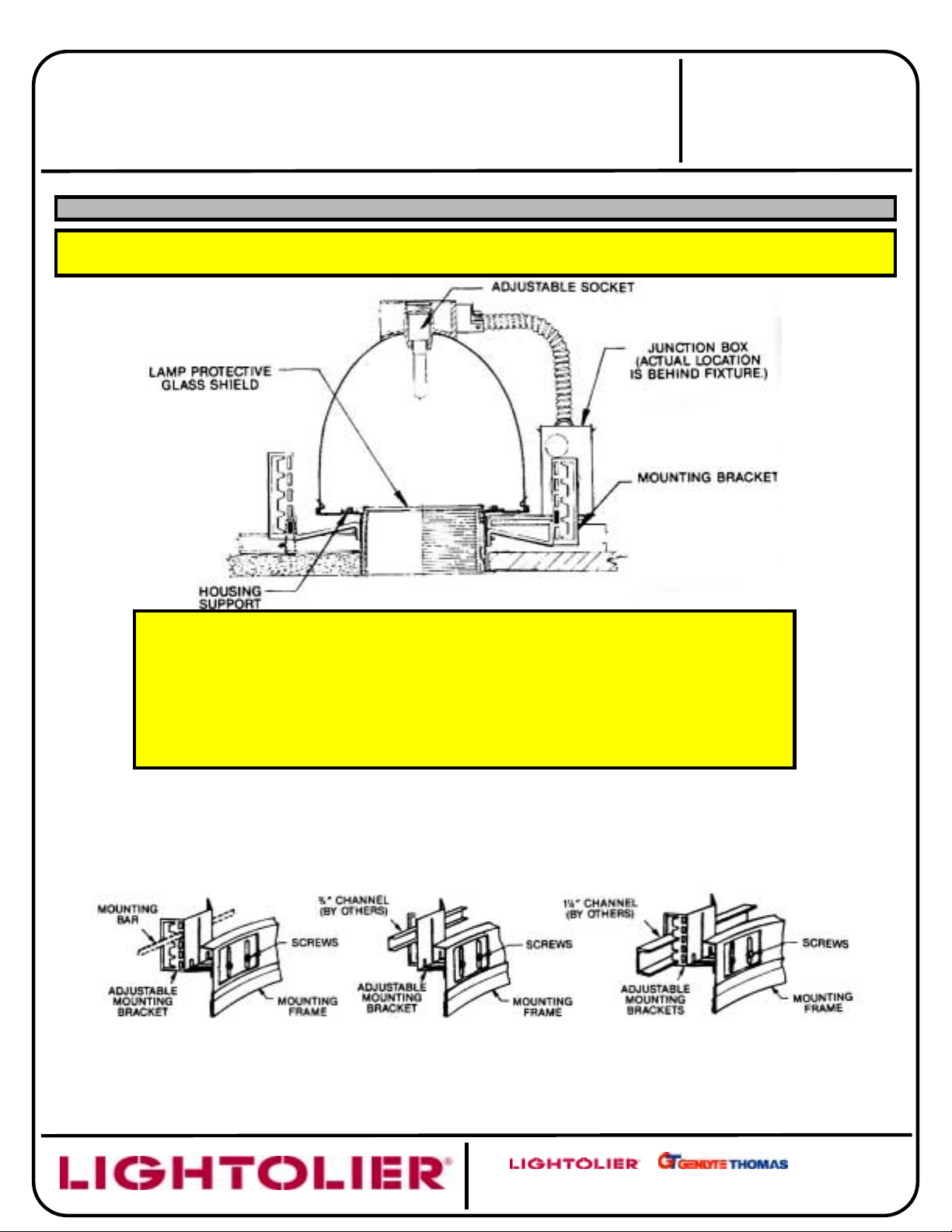
INSTALLATION PROCEDURE FOR ELLIPSOIDAL DOWNLIGHT
CAUTION: (RISK OF FIRE)
INSTALL WITH FOLLOWING MINIMUM SPACINGS BETWEEN
(A) CENTER-TO-CENTER OF ADJACENT LUMINAIRES: 48 INCHES (1219mm);
(B) TOP OF LUMINAIRE TO OVERHEAD BUILDING MEMBER:
(C)
LUMINAIRE CENTER TO SIDE BUILDING MEMBER: 24 INCHES (610mm).
DO NOT INSTALL INSULATION ABOVE, NOR WITHIN 24 INCHES (610mm) OF ANY PART
OF THE LUMINAIRE.
FIG. 1
(
TUNGSTEN-HALOGEN
INCHES (*mm);
*
)
FOR 7082, 6 INCHES (152mm)
*
FOR 7084, 3 INCHES (76mm)
A. INSTALL MOUNTING FRAME IN CEILING USING ADJUSTABLE
MOUNTING BRACKET
(1) With MOUNTING BARS (order separately):
18” – Cat. No. 1950; 27” – Cat. No 1951).
Use rectangular slots as shown.
Slide MOUNTING BARS or CHANNELS (by others) through slots in ADJUSTABLE MOUNTING BRACKET which will place the
bottom of the MOUNTING FRAME approximately in line with the finished ceiling line. Final adjustments may be made by means of
MOUNTING BRACKET SCREWS on inside of fixture.
*
(2) With ¾” channel (by others)
FIG. 3FIG. 2 FIG. 4
(3) With 1 ½” channel (by others)
A
631 Airport Road, Fall River, MA 02720
COMPANY
Page 2
INSTRUCTION SHEET NO.
p
(Fig
)
IS
IS:7084
:7084
ISIS
:7084:7084
A0302
Page 2 of 3
READ AND UNDERSTAND THESE INSTRUCTIONS BEFORE INSTALLING FIXTURE
This fixture is intended for installation in accordance with the National Electrical Code and local regulations. To
assure full compliance with local codes and regulations, check with your local electrical inspector before
installation. To prevent electric shock, turn off electricity at fuse box before proceeding.
Retain these instructions for maintenance reference.
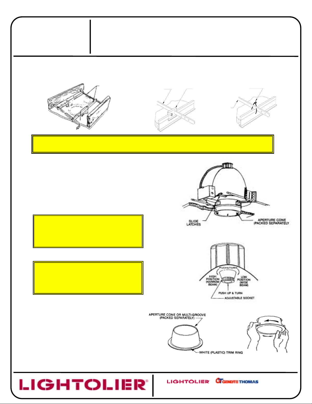
For wood joist construction:
MOUNTING BARS No. 7994 (order separately) may be
used to secure MOUNTING FRAME (Fig.5).
TELESCOPING
TELESCOPING
MOUNTING BARS
FIG. 5
NOTE: To insure proper installation it is important that MOUNTING FRAME always be
securely mounted to structural ceiling members.
B. INSTALL AND WIRE
1) Install fixture in ceiling. Adjust fixture for proper alignment
with the ceiling (Step A) and then wire fixture. White fixture
lead to neutral supply lead. Bare fixture wire to supply
ground. Use wire-nuts (local hardware items). Place all
electrical connections in the J-BOX. Attach J-BOX COVER
onto J-BOX.
2) This fixture is equipped with an ADJUSTABLE SOCKET.
The socket is pre-set to provide a wide light beam, it can be
re-set in the field to provide alternate narrow light beam by
ushing socket holder in and turning counter clockwise.
FIXTURE
For suspended ceilings:
ACCESSORY No. 1956 (order separately) may be used
with 18” or 27” MOUNTING BARS or TELESCOPING
MOUNTING BARS for quick mounting (Fig. 6) or simply
wire MOUNTING BARS to ceiling members (Fig. 7)
MOUNTING
BAR
T-BAR ANCHOR
T-Bar ANCHOR CLIPS
CLIPS
ACCESSORY
MOUNTING
BAR
FIG. 6 FIG. 7
USE SPECIFIED LAMPS
Fixture #7082: - 250 Watt T-4 Tungsten-Halogen
Frosted (Mini-Can base)
Fixture #7084: - 400 or 500 Watt T-4 Tungsten-Halogen
Frosted (Mini-Can base)
3) Place LAMP PROTECTIVE GLASS SHIELD on top of
HOUSING SUPPORT (Fig.1).
WARNING: LAMP PROTECTIVE GLASS
SHEILD MUST BE USED AT ALL TIMES
AS RECOMMENDED BY LAMP
MANUFACTURER!
NOTE: SLIDE LATCHES permit removal of reflector from
within fixture for access to splices or for relamping from
above ceiling (Fig. 8) These latches must be snapped
into position to prevent reflector from disengaging
during relamping.
C. PUSH-IN (FIG.8)
1) Push APERTURE CONE or MULTI-GROOVE BAFFLE
straight up into MOUNTING FRAME until tight against
finished ceiling. RETAINING SPRINGS on MOUNTING
FRAME (Fig.1) will secure APERTUR CONE or MULTIGROOVE BAFFLE in place.
NOTE: To remove CONE or BAFFLE, turn CONE or
BAFFLE counterclockwise while pulling downward.
After starting, use both hands to remove, if desired.
See
. 11
ONLY!
FIG. 8
FIG. 9
FIG. 10 FIG. 11
A
COMPANY
631 Airport Road, Fall River, MA 02720
Page 3
INSTRUCTION SHEET NO.
)
)
IS:7084
IS:7084
IS:7084IS:7084
A0302
Page 3 of 3
READ AND UNDERSTAND THESE INSTRUCTIONS BEFORE INSTALLING FIXTURE
This fixture is intended for installation in accordance with the National Electrical Code and local regulations. To
assure full compliance with local codes and regulations, check with your local electrical inspector before
installation. To prevent electric shock, turn off electricity at fuse box before proceeding.
Retain these instructions for maintenance reference.
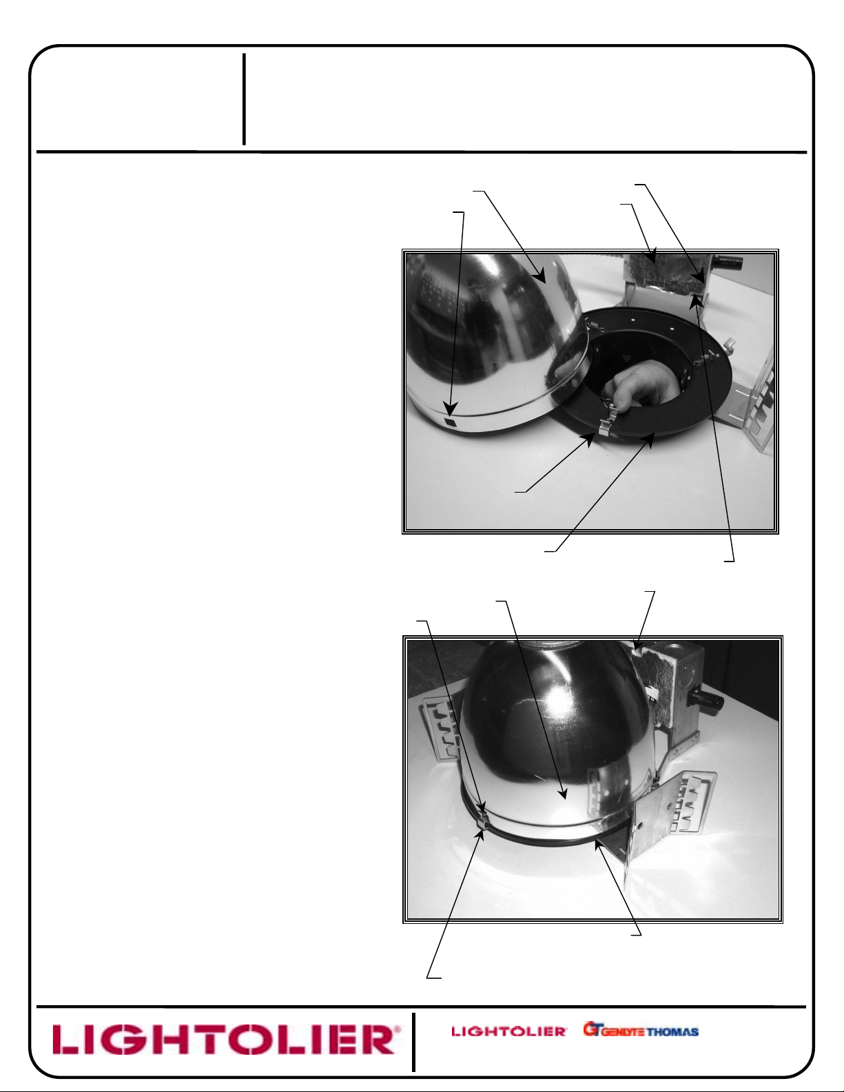
D. ACCESS TO JUNCTION BOX FROM BELOW
1) Switch off power to fixture at service panel.
2) Remove CONE (Fig. 11) and LAMP PROTECTIVE
GLASS SHEILD.
3) Remove tungsten halogen lamp (
touch with bare hands. Oil from hands could
reduce LAMP life. Use tissue paper or cloth when
relamping
4) Locate SLIDE LATCH on HOUSING SUPPORT.
Push out to the right to disengage SLIDE LATCH
from SLOT of REFLECTOR (Fig. 12). Repeat for
other two latches.
5) Push RFLECTOR up and to the side to provide
access to JUNCTION BOX. (Fig. 12).
6) To access JUNCTION BOX, lift up JUNCTION BOX
SPRING to remove JUNCTION BOX DOOR (Fig. 12).
7) After servicing, push all wires back inside JUNCTION
BOX. Insert TABS of JUNCTION BOX DOOR into
slots of JUNCTION BOX and align NOTCH of
JUNCTION BOX DOOR with JUNCTION BOX
SPRING. Snap JUNCTION BOX DOOR onto
JUNCTION BOX firmly (Fig. 12 and 13). Make sure
JUNCTION BOX DOOR is not pinching wires.
8) Install REFLECTOR back into HOUSING SUPPORT
(Fig. 13). For easier installation, the conduit from
socket to junction box should be positioned as shown
in Fig. 13.
9) Feel through the slots to align SLOTS of
REFLECTOR with SLIDE LATCHES. Note: SLIDE
LATCHES may not be visible from below, it is
recommended to first align the slot with the latch
opposite to junction box, then place REFLECTOR on
inside of HOUSING SUPPORT (Fig. 13).
10) Slide SLIDE LATCH to the left and pull back to
secure REFLECTOR (Fig. 13). Repeat for the other
two latches.
11) To ensure REFLECTOR is properly, rotate
REFLECTOR slightly to ensure SLIDE LATCHES
engage with SLOTS in REFLECTOR. The
REFLECTOR should not rotate if it is in locked
position.
12) Install lamp (see
13) Place LAMP PROTECTIVE GLASS SHIELD on top of
HOUSING SUPPORT (Fig 1).
Install CONE (Step C above
14
).
CAUTION
CAUTION: Do not
in item 3 above).
E. CARE AND MAINTENANCE OF “ALZAK”
REFLECTOR
If handling of reflectors with anodized or Alzak finish is
required, the use of clean white or plastic film gloves is
recommended to avoid fingerprints.
REFLECTOR
REFLECTOR
SLOT
SLOTS
JUNCTION BOX
DOOR
SLIDE LATCH
HOUSING SUPPORT
REFLECTOR
JUNCTION BOX
FIG. 12
JUNCTION BOX
SPRING
TAB
Anodized or Alzak surfaces can be cleaned by the
following methods:
1) Wipe off with a soft, clean, dry, lint-free cloth.
2) Wipe off with a soft, clean cloth dampened in mild
detergent solution. Rinse, then wipe dry with a lintfree cloth or paper towel.
3) Wipe off with a clean cloth dampened with a solution
of wetting agent and water (such as 2 oz. per gallon)
“Pluronic L62-F” by Wyandotte Products). Then wipe
dry.
4) Or use a liquid wash such as Glass Wax
gritty cleaning agents.
. Avoid
SLIDE LATCHES
HOUSING SUPPORT
FIG. 13
A
COMPANY
631 Airport Road, Fall River, MA 02720
 Loading...