

Page 1

Lytespan Track Lighting System 6450
Page 1 of 4 Suspension Beam System
6450
6454
7458
7469
7586
6451
7459
7680
6467
7582
7681
7468
7584
7683
Ordering Information
4' Housing 8' Housing
Catalog No. Finish Catalog No. Finish
6450
6450BK
Matte White
Black
Features
1. General De scription: Suspension Beam is a system of extruded aluminum
housings which enclose Basic or Advent Lytespan track (see Specification
Sheets 6000 and 6101). The 4'Housing is used with a 4' Individual Track, the
8' with an 8' individual or Joiner Track. End plates, couplers, splines and
mounting clips are furnished with the housings. The housings may be installed
individually, in continuous runs or in a variety of patterns and may be field-cut
(at right angles).
2. Mounting: Suspension Beam Housing can be suspended on cables or stems,
which may be spaced up to 8' apart.
3. Finish: Matte White or Black.
631 Airport Road, Fall River, MA 02720 • (508) 679-8131 • Fax (508) 674-4710
We reserve the right to change details of design, materials and finish.
www.lightolier.com © 2010 Philips Group • D0610
6451
6451BK
Labels
U. L.; I. B.E.W
Job Information Type:
Job Name:
Cat. No.:
Lamp(s):
Notes:
Matte White
Black
Page 2

Lytespan Track Lighting System 6450
Page 2 of 4 Suspension Beam System
INTERCEPT S:
L", Housing/Splice Box is used to form patterns
with Suspension Beam Housings. They include
bottom covers which snap in without tools.
In pat terns, each straight run of track is started
with an Individual and continued with Joiners.
CABLE OR STEM
Stems are recommended for housings in
straight runs or patterns and cables for housings
in patterns only. Both at tach to the housings at
any point (except at top wireway covers), may be
spaced up to 8' apart and may be shortened in
the field. The cables have an adjusting collar to
facilitate leveling. Stem length may be increased
48" with the Stem Extension Kit. A special coupler
is included to strengthen the joint between
housings.
POWER FEED AND POWER CONTINUI TY
Power is fed into the end of a straight run
of housings with a Stem Kit. Power is fed
into a pattern of housings at the Housing
Splice Boxes with a Stem Kit or a Cable Kit
with electrical feed. Power is also continued
from one track run to another through the
Housing/Splice Boxes. Auxiliary Electrical
Connectors, which are ordered in sets with
Housing/Splice Boxes, are required for power
feed or power continuity at Housing/Splice Boxes.
3" OR 4" OCTAGONAL
OUTLET (by others)
4 1/2 " DIAME TER
CANOPY
1/2" O.D. STEM
CLAMPS
631 Airport Road, Fall River, MA 02720 • (508) 679-8131 • Fax (508) 674-4710
We reserve the right to change details of design, materials and finish.
www.lightolier.com © 2010 Philips Group • D0610
Job Information Type:
Page 3

Lytespan Track Lighting System 6450
Page 3 of 4 Suspension Beam System
Continued from page 2.
CABLE OR STEM
Stems are recommended for housings in straight runs or patterns and cables for
housings in pat terns only. Both attach to the housings at any point (except at top
wireway covers), may be spaced up to 8' apar t and may be shor tened in the
field. The cables have an adjusting collar to facilitate leveling. Stem length may
be increased 48" with the Stem Ex tension Kit. A special coupler is included to
strengthen the joint between housings.
POWER FEED AND POWER CONTINUI TY
Power is fed into the end of a straight run of housings with a Stem Kit. Power is fed into a pattern of housings
at the Housing Splice Boxes with a Stem Kit or a Cable Kit with electrical feed. Power is also continued from
one track run to another through the Housing/Splice Boxes. Auxiliary Electrical Connectors, which are ordered
in sets with Housing/Splice Boxes, are required for power feed or power continuity at Housing/Splice Boxes.
3" OR 4" OCTAGONAL
OUTLET (by others)
STEM EXTENSION KIT
COMPONENTS
LEADS ( by othe rs)
Mat te White Fit tings
745 8NWH 746 8N WH
Mat te White Fit tings and
Black Elect rical Feed.
631 Airport Road, Fall River, MA 02720 • (508) 679-8131 • Fax (508) 674-4710
We reserve the right to change details of design, materials and finish.
www.lightolier.com © 2010 Philips Group • D0610
745 9NWH 746 9NWH
Job Information Type:
Page 4
Lytespan Track Lighting System 6450
Page 4 of 4 Suspension Beam System
COMPONENTS
Layouts of Stem s and Cabels
Locate cables or stems uniformly along housings
not exceeding 8' spacing. In a straight run or open
pattern, locate first and last supports approximately
1' from the ends.
Position stem for power feed at least 6" from
the end of the housing (or housing/splice box)
to which power is to be fed.
Position cable for power feed 6" to 10"from the
housing/splice box to which power is to be fed.
The 10" distance may be increased by the amount
the cable is shortened on the job.
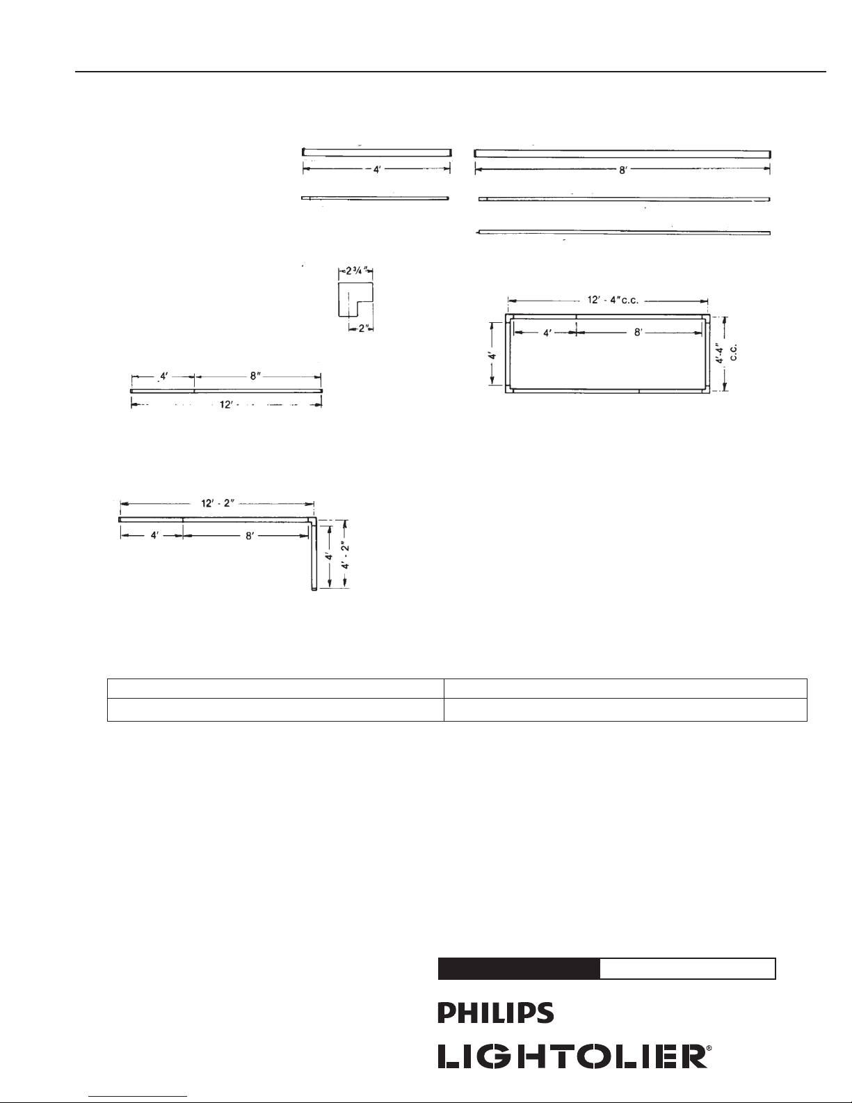
(1) 4’ Housing, (1) 4’lnd. Track
(1) 8’ Housing, (1) 8’ Joiner Track
Recommended Suppor t: Stem or Wall Mounting Kit
4' Housing 8' Housing
4' Individual Track 8' Individual Track or
Joiner Track
"L"-Housing Splice Box
(4) 4’ Housings, (4) 4’ Ind, Tracks
(2) 8’ Housings, (2) 8’ Joiner Tracks
(4) “L” Housing/Splice Boxes
(4) Sets of 2 Aux. Elect. Connectors
Recommended Suppor t: Stem or Cable
(2) 4’ Housings, (2) 4’ Ind. Tracks
(1) 8’ Housing, (1) 8’ Joiner Track
(1) “L” Housing/Splice Box
(1) Set of 2 Aux. Elect. Connectors
Recommended Suppor t: Stem or Cable
NOTE: Dimensions shown do not include End Plates.
SUSPENSION BE AM MOUN TING MAXI MUM LOAD*
Cables or Stems, spaced 8 Ft. apart 5 lb. Lytespots on 1 Ft. Spacing
631 Airport Road, Fall River, MA 02720 • (508) 679-8131 • Fax (508) 674-4710
We reserve the right to change details of design, materials and finish.
www.lightolier.com © 2010 Philips Group • D0610
Job Information Type:
 Loading...