

Page 1
INSTRUCTION SHEET NO.
IS:1004ICV
B1204 Page 1 of 4
INSTALLATION PROCEDURE FOR LOW VOLTAGE
INSULATED CEILING FRAME-IN-KIT 1004ICV, 1004ICVN
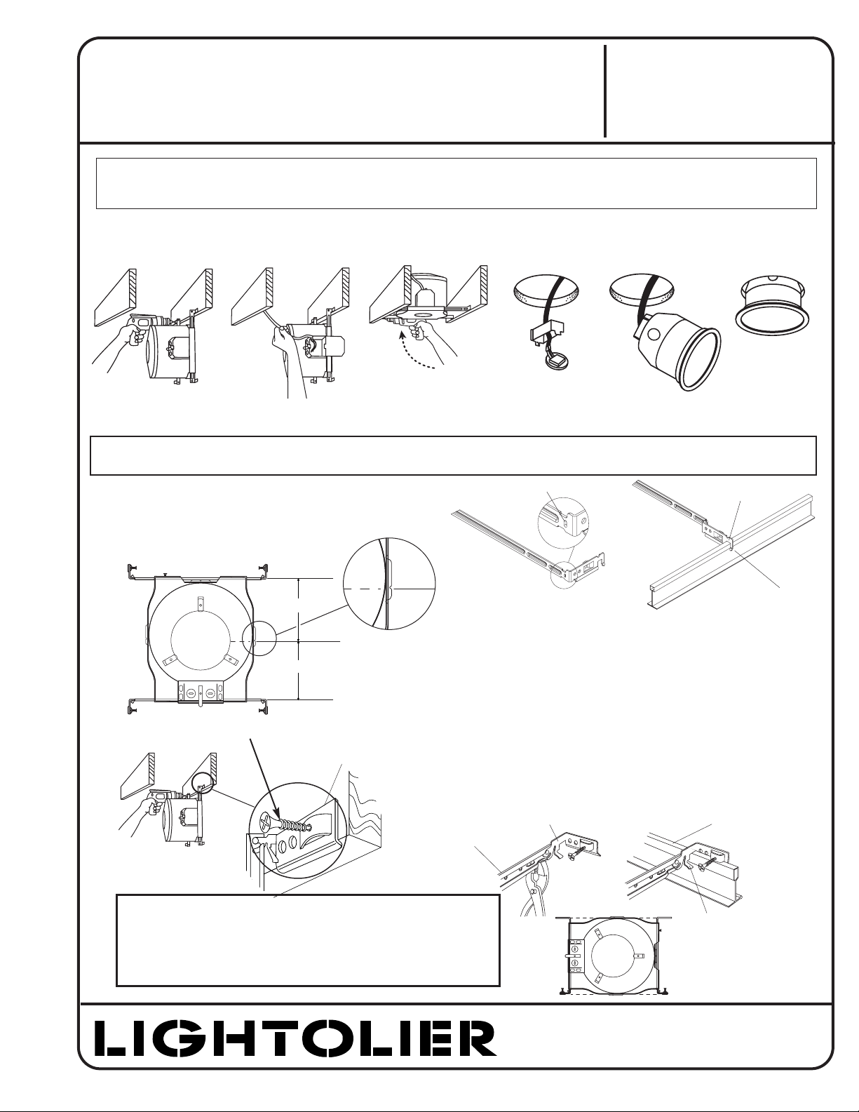
1. FRAME-IN (Fig. A)
Locate fixture along joist and line up bottom edge of HINGED
MOUNTING BAR with the bottom of joist and fasten in place.
Fig. A
Frame-In
Fig. B
Wire-In
Fig. C
Swing-Up
Fig. D
Close-In
Fig. E
Snap-On
Fig. F
Push-Up
For suspended ceilings:
• Rotate HINGED BAR ENDS to position shown
and fully extend bars.
• Crimp bottom of edge of CHANNEL to prevent
rotation of HINGED BAR ENDS.
• Bend NON-HINGED end of mounting bar at
featured hole location and extend out.
• Position notched area of MOUNTING BARS onto
T-BAR and lock by bending TAB underneath
T-BAR BEAD as shown.
• For suspended ceiling, make certain that bottom
of Mounting Frame is no higher than 1” above
ceiling line.
READ AND UNDERSTAND THESE INSTRUCTIONS BEFORE INSTALLING FIXTURE
This fixture is intended for installation in accordance with the National Electrical Code and local regulations.
To assure full compliance with local codes and regulations, check with your local electrical inspector before
installation. To prevent electrical shock, turn off electricity at fuse box before proceeding.
Retain these instructions for maintenance reference.
®
LIGHTOLIER a GENLYTE company.
631 Airport Road, Fall River, MA 02720
NEW CONSTRUCTION
NOTE: I.C. Frame-in Kit may be used in direct contact with insulation.
WARNING: USE ONLY WITH LIGHTOLIER REFLECTOR TRIMS MARKED WITH I.C. LAMPING INFORMATION. USE OF OTHER
MANUFACTURERS’ TRIMS VOIDS THE UNDERWRITERS LABORATORIES LISTING AND COULD CONSTITUTE A FIRE HAZARD
HINGED MOUNTING BAR
5 5/
8”
6”
CENTER LINE OF
APERTURE OPENING
Fig. G
Note: Integral nail version available
TAB
T-BAR
HINGED BAR ENDS
CHANNEL
TAB
BEND AT TAB
BEND AT HOLE
FOR JOIST SPACING LESS THAN 16” ON CENTER (TO 12” ON CENTER):
• MOUNTING BAR CHANNELS can be shortened and used as
nailing legs in tight spaces. Simply remove INNER BAR from
holed CHANNEL, bend CHANNEL at appropriate point and
use extra screw to secure it to the joist. (Fig. G)
Page 2
READ AND UNDERSTAND THESE INSTRUCTIONS BEFORE INSTALLING FIXTURE
This fixture is intended for installation in accordance with the National Electrical Code and local regulations.
To assure full compliance with local codes and regulations, check with your local electrical inspector before
installation. To prevent electrical shock, turn off electricity at fuse box before proceeding.
Retain these instructions for maintenance reference.
LIGHTOLIER a GENLYTE company.
631 Airport Road, Fall River, MA 02720
INSTRUCTION SHEET NO.
IS:1004ICV
B1204 Page 2 of 4
2. WIRE-IN (Fig. B)
Open hinged J-BOX COVER fully to its locked position (lift
slightly to unlock).
Open hinged KNOCK OUT to allow NON-METALLIC CABLE
to enter JUNCTION BOX. Push CABLE through CLAMP.
Note:Wiring and connections must not be placed in JUNCTION
BOX in a manner which will interfere with the CLAMPS
action to provide strain relief.
Wire to SUPPLY LEADS. WHITE FIXTURE LEAD to NEUTRAL
SUPPLY LEAD. BLACK FIXTURE LEAD to HOT (120V) SUPPLY
LEAD. BARE FIXTURE WIRE to SUPPLY GROUND. Use wirenuts
(local hardware item). Place all electrical connections in the
J-BOX and close the J-BOX COVER.
3. SWING-UP (Fig. C)
Extend MOUNTING BAR to reach opposite joist and fasten in
place. Adjust fixture to desired position along MOUNTING BAR
and lock in place using locking screw.
4. CLOSE-IN (Fig. D)
Install plasterboard or other dry type ceiling. Hole in board
can be cut either on the floor or after the board is secured to
the ceiling using MOUNTING FRAME opening as cutting
guide. Make sure ROTO-CLIPS are rotated out of hole area to
be cut, also making sure that socket and wiring are positioned
away from hole area.
Roto Clips can only be rotated counterclockwise. This detail allows easy removal of reflector trim by
rotating TRIM counterclockwise and permits installing Reflector
Trim tightly against the ceiling surface by rotating trim clockwise
after pushing Trim into ceiling.
5.
AIRSEAL
®
INSTALLATION (optional)
Install a bead of silicone caulking compound between the
ceiling opening and edge of HOUSING. Housings are tested in
accordance with ASTM E 283 (max 2 cfm @ 75 pa) and comply
with WSEC & MEC when installed as instructed.
6. SNAP-ON (Fig. E)
Important - Insert SOCKET CUP in neck
of REFLECTOR making sure SPRING TABS
fully engage into SLOTS in REFLECTOR.
7. PUSH-UP (Fig. F)
Push REFLECTOR TRIM straight up until
it is tight against ceiling.
SEE SEPARATE
REFLECTOR TRIM
INSTRUCTION
SHEETS
U.S. AND FOREIGN PATENTS PENDING
}
HINGED KNOCK OUT
J-BOX COVER
NON-METALLIC
SHEATHED CABLE
(12 OR 14 GAUGE ONLY)
CABLE CLAMP
JUNCTION BOX
®
DEFORM MATERIAL AT
ANY CORNER OF FRAME
FOR ADDITIONAL LOCK
IF NEEDED
LOCKING SCREW
Page 3

INSTRUCTION SHEET NO.
IS:1004ICV
B1204 Page 3 of 4
READ AND UNDERSTAND THESE INSTRUCTIONS BEFORE INSTALLING FIXTURE
This fixture is intended for installation in accordance with the National Electrical Code and local regulations.
To assure full compliance with local codes and regulations, check with your local electrical inspector before
installation. To prevent electrical shock, turn off electricity at fuse box before proceeding.
Retain these instructions for maintenance reference.
®
LIGHTOLIER a GENLYTE company.
631 Airport Road, Fall River, MA 02720
8. LAMPING (Fig. H)
1. Make sure that power is OFF when lamping or relamping.
Remove LAMP RING from TRIM by pulling straight down.
2. Remove LAMP SHIELD from LAMP RING.
3. Place LAMP SHIELD on back of LAMP (MR-16) and insert both
between LAMP SPRINGS until face of lamp sits firmly on GLASS LAMP
GUARD (Fig. J).
WARNING: RISK OF FIRE. LAMP SHIELD MUST BE INSTALLED.
4. Attach SOCKET to bi-pin prongs on LAMP.
5. Insert LAMP RING with LAMP SHIELD, LAMP and GLASS LAMP
GUARD back into TRIM.
FEMALE CONNECTORS
(ATTACHED TO FIXTURE WIRES)
MALE CONNECTORS
(ATTACHED TO SOCKET WIRES)
MR16 SOCKET
LAMP SPRING
Fig. H
LAMP SHIELD
INSULATING SLEEVING
GLASS LAMP GUARD
SOCKET
LAMP RING
Fig. J
NOTE: 1. LOW VOLTAGE FIXTURES should be
dimmed only with special dimmers intended
specifically for that purpose. Use Lightolier
Lytemode, Scenist, Crescendo VA, Neptune VA,
Precision VA, Easyset VA, Sunrise VA, Radiant
VA or equivalent products by others or variable
autotransformers or electronic dimmers
intended for use with low voltage fixtures.
2. Low voltage fixtures may produce audible
sound which may be objectionable in acoustically critical areas.
LAMP
WARNING: 1. LAMP MANUFACTURERS REQUIRE THE GLASS LAMPGUARD BE IN PLACE BEFORE ENERGIZING LAMP, AND THAT GREAT
CARE MUST BE TAKEN THAT LAMP IS FULLY COOLED BEFORE RELAMPING. AVOID FINGER MARKS ON INSIDE OF LAMP FOR THEY MAY
CAUSE SHORT LAMP LIFE AND POSSIBLE BREAKAGE. 2. USE ONLY REFLECTOR TRIMS
PROVIDED BY LIGHTOLIER INC. USE OF OTHER
MANUFACTURER'S REFLECTOR TRIMS VOIDS THE UNDERWRITERS LABORATORIES
LISTING AND COULD CONSTITUTE A FIRE HAZARD.
Page 4

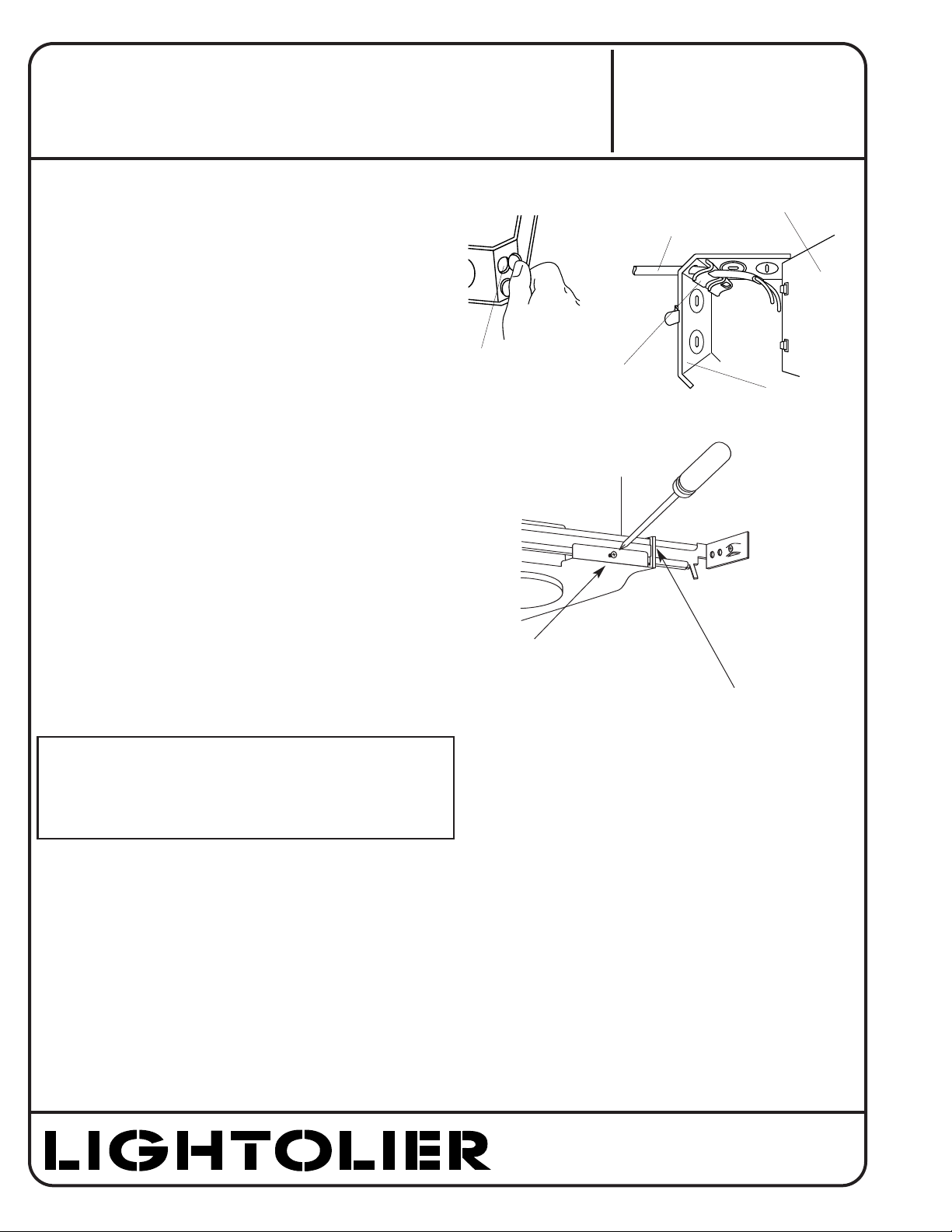
9. TRANSFORMER REPLACEMENT (Fig. K)
1. Make sure power is off.
2. Remove REFLECTOR TRIM from ceiling.
3. Remove SCREW and lift TRANSFORMER off bracket.
4. Remove J-BOX COVER by removing wing nut.
5. Unsplice primary leads in J-BOX.
6. Remove primary leads from J-BOX cover and clip attached to side
of housing.
7. Cut secondary (red) leads 6" to 8" from TRANSFORMER and discard faulty transformer.
8. Install new TRANSFORMER:
(WARNING: RISK OF FIRE. Transformer contains fixture thermal
protector. Replace as shown and described below. Use only
replacement transformer obtained from LIGHTOLIER.)
a. Splice secondary (red) leads to socket leads.
b. Attach TRANSFORMER to BRACKET with SCREW, making
sure that the side of transformer that has the wire leads is
facing the housing wall (Fig.L)
c. Put primary leads through clip and bushing in the J-BOX
COVER.
e. Wire primary leads to supply leads.
f. Replace J-BOX COVER.
g. Install REFLECTOR TRIM.
Fig. K
ROTO CLIPS
JUNCTION BOX
MAX. OF (6) #12 AWG BRANCH
CIRCUIT CONDUCTORS SUITABLE
FOR AT LEAST 90° C PERMITTED
IN JUNCTION BOX.
TRANSFORMER
PRIMARY: 120V, 60HZ
SECONDARY: 110V, 50W LOAD
SCREW
SECONDARY
(RED) LEADS
PRIMARY
LEADS
CLIP
INSTRUCTION SHEET NO.
IS:1004ICV
B1204 Page 4 of 4
READ AND UNDERSTAND THESE INSTRUCTIONS BEFORE INSTALLING FIXTURE
This fixture is intended for installation in accordance with the National Electrical Code and local regulations.
To assure full compliance with local codes and regulations, check with your local electrical inspector before
installation. To prevent electrical shock, turn off electricity at fuse box before proceeding.
Retain these instructions for maintenance reference.
®
LIGHTOLIER a GENLYTE company.
631 Airport Road, Fall River, MA 02720
APERTURE
HOLE
TRANSFORMER
WIRE LEADS
HOUSING
WALL
Fig. L
 Loading...