

LIGHTNING PROTECTION INTERNATIONAL PTY LTD Stormaster ESE, Stormaster 15, Stormaster 30, Stormaster 50, Stormaster 60 Installation Manual
HidgbVhiZg:H:
LIGHTNING PROTECTION INTERNATIONAL PTY LTD
ABN 11 099 190 897
www.lpi.com.au

Lightning Protection International Pty Ltd
ABN 11 099 190 897
PO Box 379 Kingston, Tasmania, Australia 7051
Phone: +61 3 62271955
Fax: +61 3 62291900
Email: info@lpi.com.au
Web: www.lpi.com.au
STORMASTER ESE INSTALLATION MANUAL
As a result of continuing research and product development in the area of lightning and
lightning protection, LPI reserves the right to alter any detail contained within at any
time without notice.
Prior to installation of the Stormaster ESE system, installers should check with LPI or an
authorised distributor to conrm they have the most recent version of the Stormaster
ESE Installation manual.
It should be noted that 100% (100 percent) protection level for direct lightning strikes
is not possible and cannot be provided due to the lightning discharge process being a
natural atmospheric event.
Stormaster ESE Lightning Protection System
System Owner:_____________________________________________________
Date Installed:_____________________________________________________
Installation Contractor:______________________________________________
Supplied by:_______________________________________________________
Location of Installation
:____________________________________________
Document 36 II Stormaster Version 1.02 © Copyright 2008 LPI 1
Lightning Protection International Pty Ltd

2 Document 36 II Stormaster Version 1.02 © Copyright 2008 LPI
Protection Performance 3
Warranty 4
Lightning Protection 4
General Safety Guidelines 5
Recommended Installation Method 5
Checking Lightning Protection
Components Supplied 13
LPI Stormaster ESE Installation 13
Installation of the Lightning Earth 14
Ground Resistance Lowering Compounds 16
Bonding the Lightning Earth 16
Labelling 16
Installation of the HVSC Downconductor 16
Hauling the HVSC Downconductor 17
HVSC Downconductor clearance holes 18
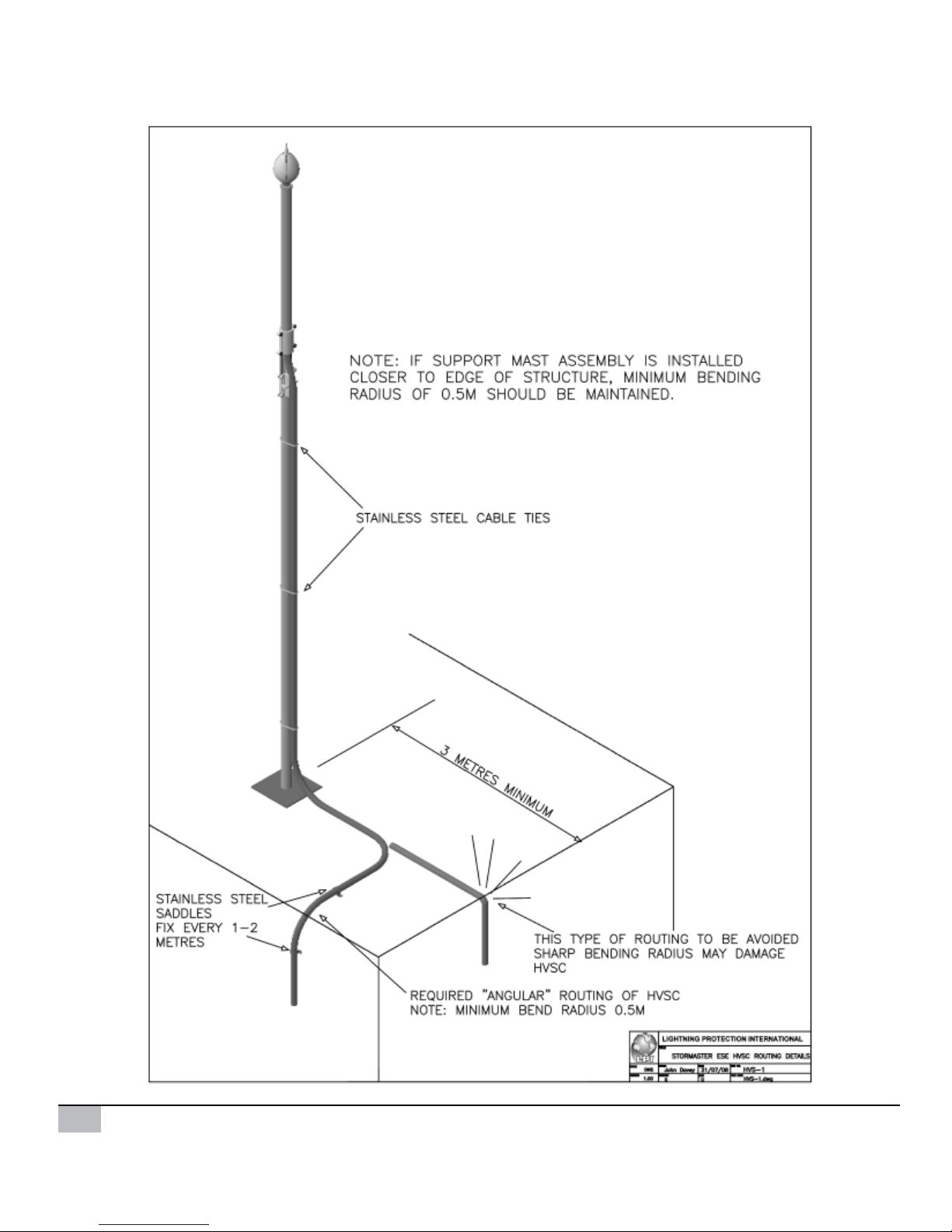
Routing 19
Fixing the HVSC Downconductor 21
Installation of Conventional
Downconductors 21
Installation of Stormaster GI Terminal
to threaded pipe 23
Termination of the HVSC Lower End 25
Lower Termination of Conventional
Downconductor to the Lightning Earth 28
Termination of the HVSC Upper End 29
Connection of Factory Pre-Terminated HVSC
(Upper End) to Stormaster Terminal 35
Labelling 35
Masts 36
Types of Mast Configurations 36
Mast Bases 37
Mast Couplings and Guying Points 38
Guying 39
Preparation for raising the Mast into
position 40
Raising of the Mast 40
Lightning Strike Recorder (LSR1) 42
Certification 44
Operation and Maintenance 44
Testing the Stormaster Terminal 45
Testing the Lightning Earth and the
HVSC Downconductor 45
Contents
Document 36 II Stormaster Version 1.02 © Copyright 2008 LPI 3
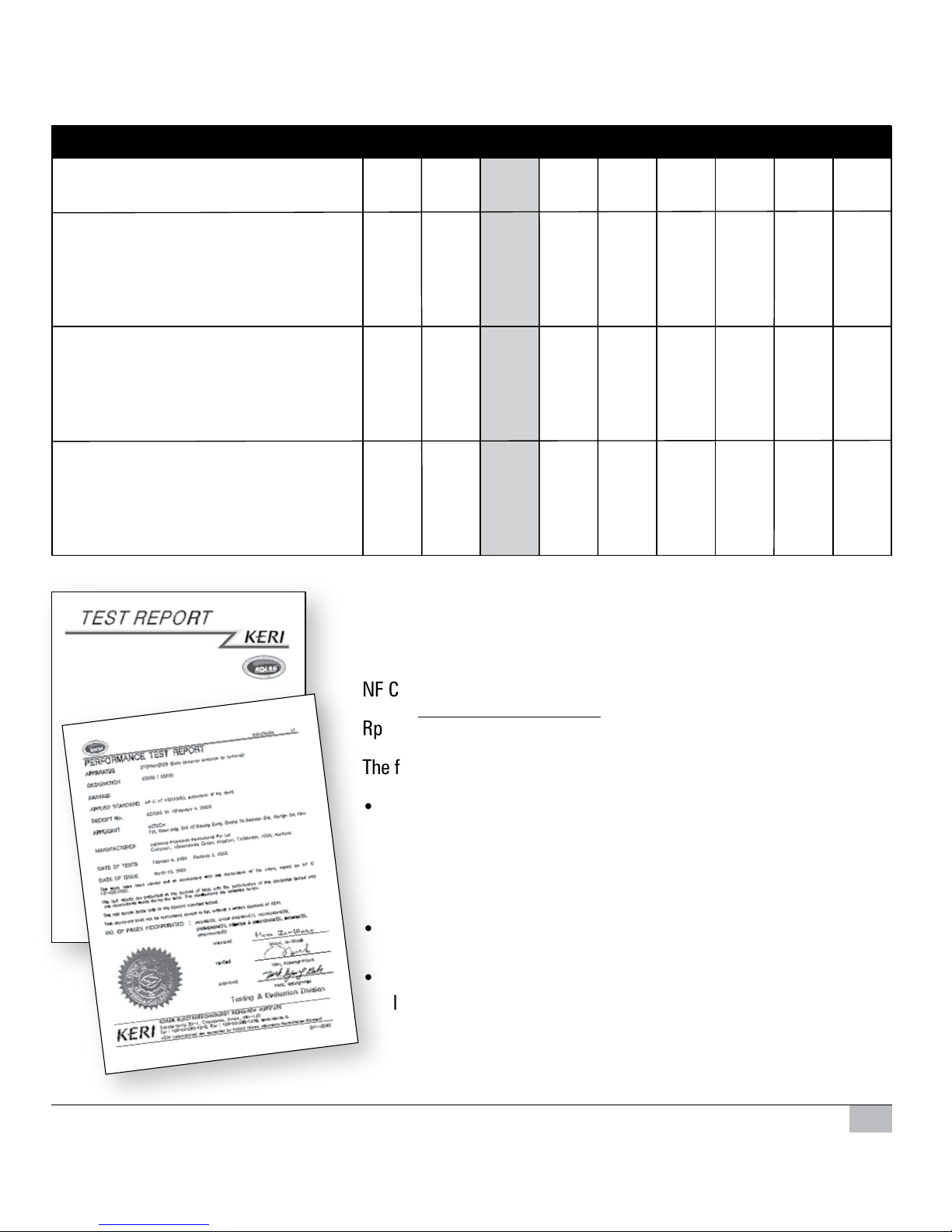
The protection radius (Rp) of a Stormaster ESE terminal is calculated
using the following formula as defined by the French National Standard
NF C 17-102 (July 1995).
Rp = √h(2D-h) + ∆T(2D + ∆T) for ≥5m where:
The following key parameters determine the calculation of RP.
• ∆T as established during the test.
Stormaster-ESE-15 = ∆T (µs) 15
Stormaster-ESE-30 = ∆T (µs) 30
Stormaster-ESE-50 = ∆T (µs) 50
Stormaster-ESE-60 = ∆T (µs) 60
• h=actualheightofStormasterterminalabovetheareatobe
protected (m).
• D(inm)dependsontheselectedlevelofprotection,protection
levels are specified in annex B of the standard NF C 17-102.
D = 20m for protection level 1 (High Protection)
D = 45m for protection level 2 (Medium protection)
D = 60m for protection level 3 (Standard protection)
Protection Performance
PROTECTION RADIUS (M) - (Rp)
h = height of Stormaster terminal 2 4 5 6 10 15 20 45 60
above area to be protected (m)
Protection Level 1
(High Protection)
Stormaster 15 13 25 32 32 33 34 35 35 35
Stormaster 30 19 28 48 48 49 50 50 50 50
Stormaster 50 28 55 68 69 69 70 70 70 70
Stormaster 60 32 64 79 79 79 80 80 80 80
Protection Level 2
(Medium Protection)
Stormaster 15 18 36 45 46 49 52 55 60 60
Stormaster 30 25 50 63 64 66 68 71 75 75
Stormaster 50 35 69 86 87 88 90 92 95 95
Stormaster 60 40 78 97 97 99 101 102 105 105
Protection Level 3
(Standard Protection)
Stormaster 15 20 41 51 52 56 60 63 73 75
Stormaster 30 28 57 71 72 75 77 81 89 90
Stormaster 50 38 76 95 96 98 100 102 110 110
Stormaster 60 44 87 107 107 109 111 113 120 120
4 Document 36 II Stormaster Version 1.02 © Copyright 2008 LPI
Warranty
LPI’s Stormaster ESE terminals are guaranteed against defects in materials and workmanship
for a period of 5 years from the original sales date when it was purchased from LPI or one of its
authorised distributors.
The warranty is limited to the ex factory cost of replacement of equipment providing it has been
installed and or certied by LPI or its distributor. All other costs such as freight, re-installation,
loss of prot, insurance premiums are not included.
Responsibility for other direct or indirect damages or death is also specically excluded from
the warranty.
The range of Stormaster ESE terminals (or to our knowledge any other lightning protection
system) cannot provide 100% protection and therefore it is not inferred.
As conrmation of the above paragraph we refer to French Standard NF C 17-102.
Lightning Protection
Comments on the French Standard NF C 17-102.
We refer to the section in the standard titled “foreward” where it states the following:
“As in the case with anything related to the natural elements, a lightning protection system
designed and installed in accordance with the standard, cannot guarantee absolute protection
to structures, persons or objects: however , applying this standard will signicantly reduce the
risk of protected structures being damaged by lightning.”
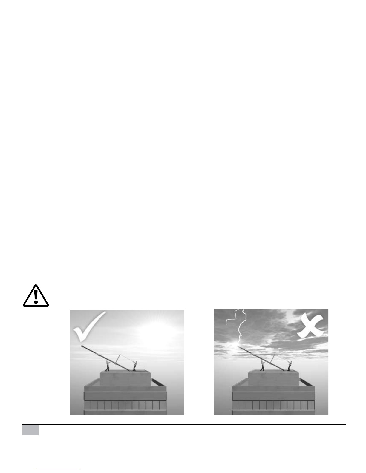
The LPI Stormaster ESE Terminal should only be installed during storm free periods.
Figure 1.

Document 36 II Stormaster Version 1.02 © Copyright 2008 LPI 5
• Ensure safe working environments and practices to local codes.
• Use of personal protective equipment during installation.
• Use mechanical methods of raising and installing masts over 6m.
• Cordon off area below installation point.
• Check for overhead powerlines or any other obstructions before lifting or raising.
• Ensure enough man power to safely conduct all aspects of installation.
• The installation must conform to all relevant local standards and regulations.
General Safety Guidelines
Recommended Installation Method
To assist in the installation of the Stormaster ESE terminal and accessories, refer to drawings
STA-01, STA-02, STA-03, STA-04, STA-05, STA-06 and HVS-1 as illustrated on pages 6 to 12.
1. Installation of the lightning earth.
2. Installation of the HVSC Downconductor.
3. Lower termination of the HVSC Downconductor and connection to the lightning earth.
4. Upper termination of the HVSC Downconductor and connection to the Stormaster ESE
terminal.
5. Preparation and raising of the mast into position.
6 Document 36 II Stormaster Version 1.02 © Copyright 2008 LPI
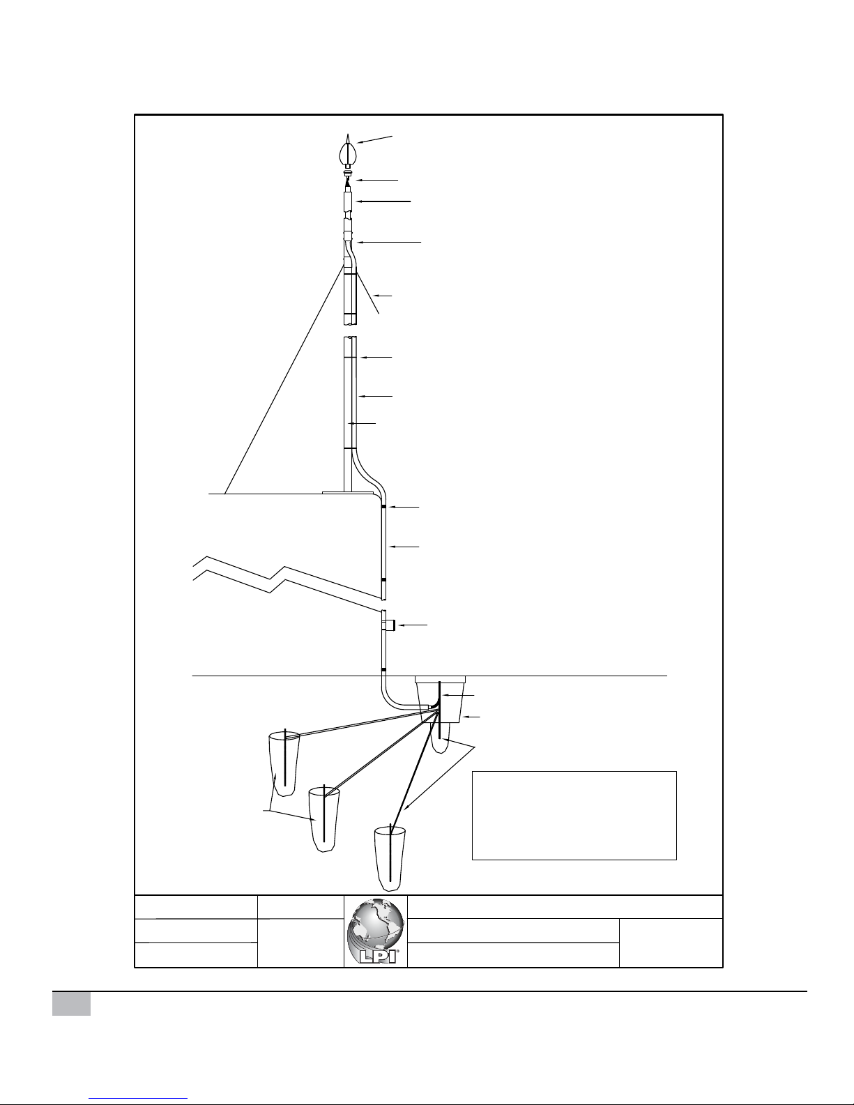
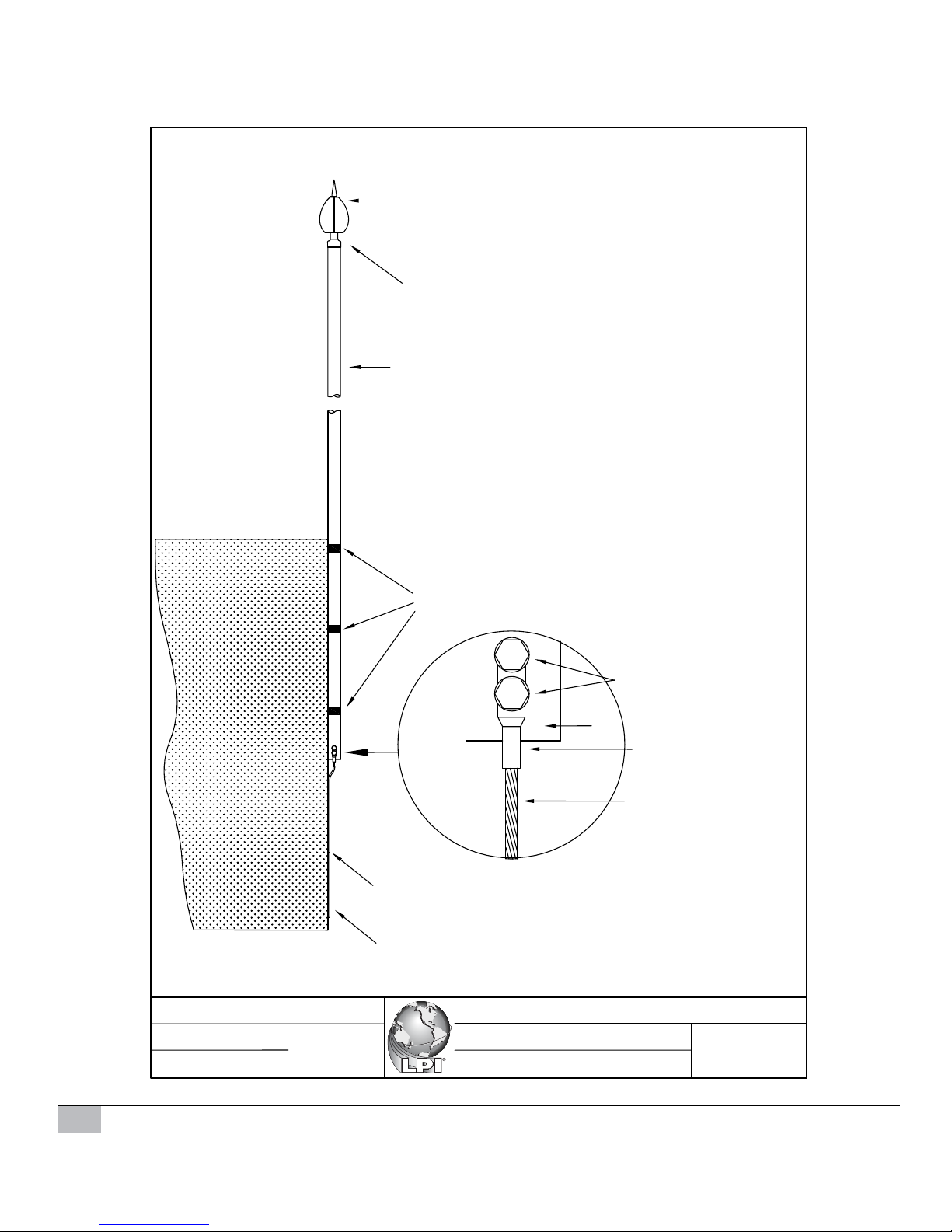
Figure 2.
LPI STORMASTER ESE TERMINAL
LPI UPPER TERMINATION KIT
LPI FRP SUPPORT MAST
LPI GUY KIT
LPI CABLE TIES
LPI HIGH VOLTAGE SHIELDED CABLE
LPI LOWER MAST ASSEMBLY WITH BASE
LPI SADDLES AND FIXINGS
LPI HIGH VOLTAGE SHIELDED CABLE
LPI LIGHTNING STRIKE RECORDER
LPI LOWER TERMINATION KIT
LPI INSPECTION PIT
LPI EARTHING SYSTEM
LPI GROUND RESISTANCE
IMPROVEMENT POWDER
BUILDING
IMPORTANT:
Stormaster ESE terminal to be
a minimum of 2 metres above
the highest point of the building.
Recommended clearance
height = 5 metres.
ORDERING CODE: STORMASTER-ESE-15
ORDERING CODE:
UTERMKIT-Mk2
ORDERING CODE:ILCOUPLING
ORDERING CODE:
FRP-2M
FRP-3M
FRP-4M
FRP-4.6M
ORDERING CODE: GUYKIT-4M
GUYKIT-4M-SS
GUYKIT-7M
GUYKIT-7M-SS
ORDERING CODE: S/S-CABTIES-STD
S/S-CABTIES-LONG
ORDERING CODE: HVSC-PM
ORDERING CODE: ALUMB-3M
ALUMB-4M
ALUMB-5M
ALUMB-6M
ORDERING CODE: SAD/FIX
ORDERING CODE: LSR1
ORDERING CODE:
LTERMKIT
ORDERING CODE:
EPIT-P
ORDERING CODE: GRIP-10
EPIT-C
TYPICAL PRODUCTS REQUIRED FOR RADIAL
LP EARTH
4 X CBER458
4 X RTC1625A
1 X EPIT-P
1 X GRIP-10
30 X CT253
STORMASTER-ESE-30
STORMASTER-ESE-50
STORMASTER-ESE-60
LPI INLINE COUPLING
Lightning Protection International Pty Ltd
Drawn
Date
Scale
Title
File
Version
STA-01
Stormaster ESE terminal assembly
component details
ESE Installation Type 1.dwg
NTS
9/4/2008
John Davey
V1.00
Document 36 II Stormaster Version 1.02 © Copyright 2008 LPI 7
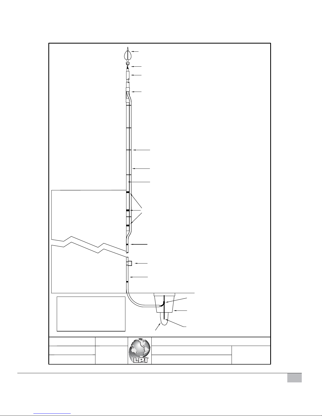
Figure 3.
LPI UPPER TERMINATION KIT
LPI FRP SUPPORT MAST
LPI CABLE TIES
LPI HIGH VOLTAGE SHIELDED CABLE
LPI LOWER MAST ASSEMBLY
LPI SADDLES FOR CANTILEVERING MAST
LPI HIGH VOLTAGE SHIELDED CABLE
LPI LIGHTNING STRIKE RECORDER
LPI LOWER
TERMINATION KIT
LPI INSPECTION PIT
LPI EARTHING SYSTEM
EXISTING STRUCTURE
IMPORTANT:
One third of the mast height
must be securely fixed to the
structure.
Stormaster ESE terminal to be
a minimum of 2 metres above
the highest point of the building.
Recommended clearance
height = 5 metres.
LPI SADDLES AND FIXINGS
LPI STORMASTER ESE TERMINAL ORDERING CODE: STORMASTER-ESE-15
ORDERING CODE: UTERMKIT-Mk2
ORDERING CODE: ILCOUPLING
ORDERING CODE: FRP-2M
FRP-3M
FRP-4M
FRP-4.6M
ORDERING CODE: S/S-CABTIES-STD
S/S-CABTIES-LONG
ORDERING CODE:
HVSC-PM
ORDERING CODE:
ALUM-3M
ALUM-4M
ALUM-5M
ALUM-6M
ORDERING CODE:
SAD/FIX
ORDERING CODE: LSR1
ORDERING CODE:
LTERMKIT
ORDERING CODE:
EPIT-P
ORDERING CODE: GRIP-10
EPIT-C
TYPICAL PRODUCTS REQUIRED FOR
RADIAL LP EARTH
4 X CBER458
4 X RTC1625A
1 X EPIT-P
1 X GRIP-10
30 X CT253
STORMASTER-ESE-30
STORMASTER-ESE-50
STORMASTER-ESE-60
ORDERING CODE:
CANTSAD
LPI INLINE COUPLING
LPI GROUND RESISTANCE IMPROVEMENT COMPOUND
(3 PER SET)
Lightning Protection International Pty Ltd
Drawn
Date
Scale
Title
File
Version
STA-02
Stormaster ESE terminal assembly
component details
ESE Installation Type 2.dwg
NTS
9/4/2008
John Davey
V1.00
8 Document 36 II Stormaster Version 1.02 © Copyright 2008 LPI
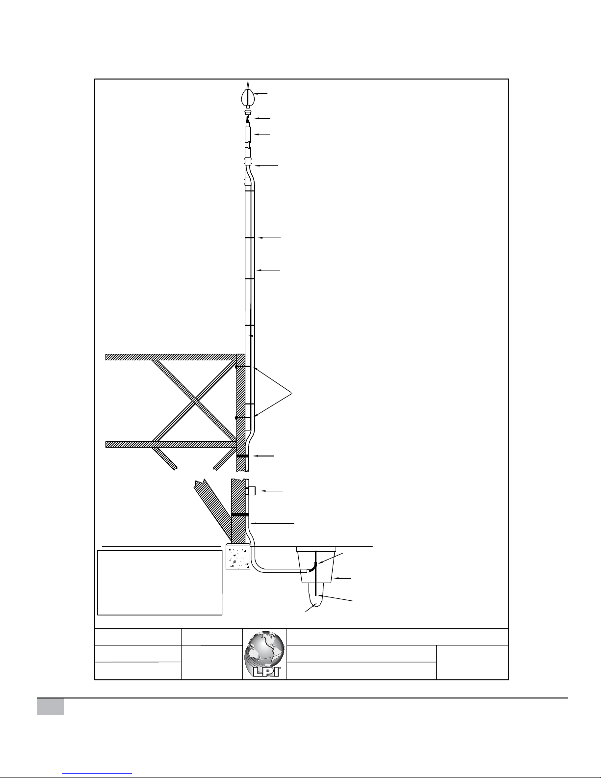
Figure 4.
LPI STORMASTER ESE TERMINAL
LPI UPPER TERMINATION KIT
LPI FRP SUPPORT MAST
LPI CABLE TIES
LPI HIGH VOLTAGE SHIELDED CABLE
LPI LOWER MAST ASSEMBLY
LPI U-BOLT
LPI HIGH VOLTAGE SHIELDED CABLE
LPI LIGHTNING STRIKE RECORDER
LPI LOWER
TERMINATION KIT
LPI INSPECTION PIT
LPI EARTHING SYSTEM
TYPICAL TOWER
IMPORTANT:
One third of the mast height
must be securely fixed to the
structure.
Stormaster ESE terminal to be
a minimum of 2 metres above
the highest point of the building.
Recommended clearance
height = 5 metres.
LPI BEAM AND CLAMP SUPPORT
ORDERING CODE:STORMASTER-ESE-15
ORDERING CODE:
ORDERING CODE: ILCOUPLING
ORDERING CODE:
FRP-2M
FRP-3M
FRP-4M
FRP-4.6M
ORDERING CODE: S/S-CABTIES-STD
S/S-CABTIES-LONG
ORDERING CODE:
HVSC-PM
ORDERING CODE:
ALUM-3M
ALUM-4M
ALUM-5M
ALUM-6M
ORDERING CODE:
BEAM CLAMP/CABLE
SUPPORT-HVSC
ORDERING CODE: LSR1
ORDERING CODE:
LTERMKIT
ORDERING CODE:
EPIT-P
ORDERING CODE: GRIP-10
EPIT-C
TYPICAL PRODUCTS REQUIRED FOR
RADIAL LP EARTH
4 X CBER458
4 X RTC1625A
1 X EPIT-P
1 X GRIP-10
30 X CT253
STORMASTER-ESE-30
STORMASTER-ESE-50
STORMASTER-ESE-60
U-BOLT
UTERMKIT-Mk2
LPI INLINE COUPLING
ORDERING CODE:
(2 PER SET)
LPI GROUND RESISTANCE IMPROVEMENT POWDER
Lightning Protection International Pty Ltd
Drawn
Date
Scale
Title
File
Version
STA-03
Stormaster ESE terminal assembly
component details
ESE Installation Type 3.dwg
NTS
9/4/2008
John Davey
V1.00
Document 36 II Stormaster Version 1.02 © Copyright 2008 LPI 9
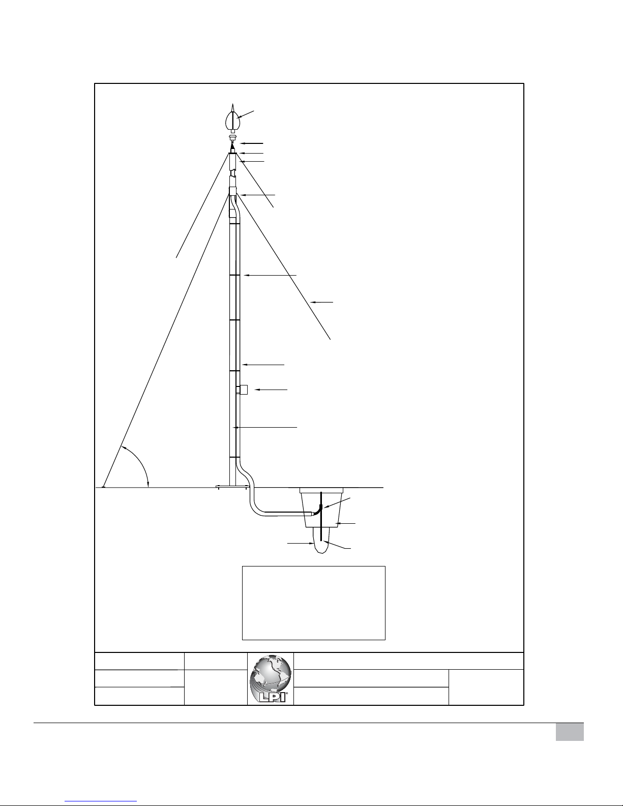
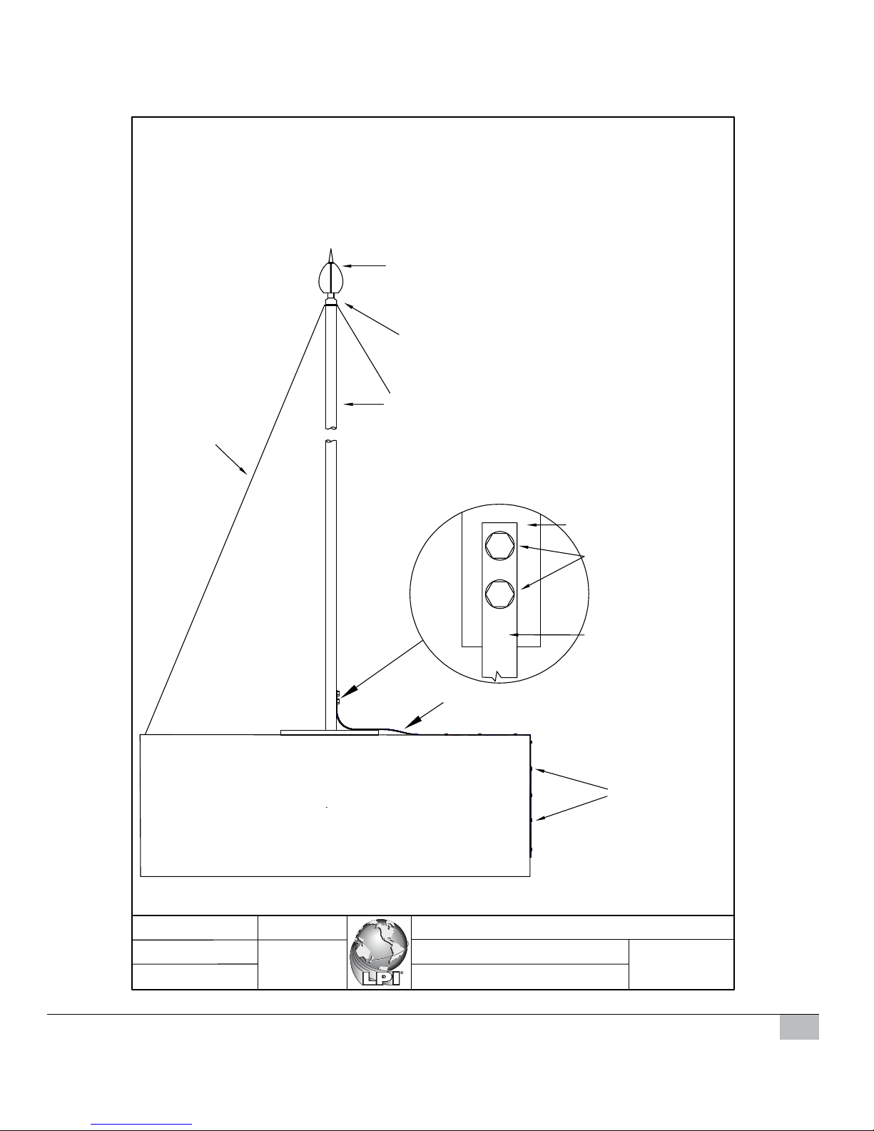
Figure 5.
LPI STORMASTER ESE TERMINAL
LPI UPPER TERMINATION KIT
LPI FRP SUPPORT MAST
LPI CABLE TIES
LPI HIGH VOLTAGE SHIELDED CABLE
LPI LOWER MAST ASSEMBLY
LPI LIGHTNING STRIKE RECORDER
LPI LOWER
TERMINATION KIT
LPI INSPECTION PIT
LPI EARTHING SYSTEM
LPI GROUND RESISTANCE
IMPROVEMENT POWDER
IMPORTANT:
Stormaster ESE terminal to be a minimum of 2
metres above the highest point of the building.
Recommended clearance height = 5 metres.
LPI GUY RING
LPI GUY KIT
DO NOT OVER TENSION GUY WIRES
(SLIGHTLY SAGGING)
GUY WHERE
NECESSARY
PREFERRED ANGLE
60-45 DEGREES
6
0
4
5
ORDERING CODE:STORMASTER-ESE-15
ORDERING CODE:
ORDERING CODE:ILCOUPLING
ORDERING CODE:FRP-2M
FRP-3M
FRP-4M
FRP-4.6M
ORDERING CODE: S/S-CABTIES-STD
S/S-CABTIES-LONG
ORDERING CODE:
HVSC-PM
ORDERING CODE:
ALUMB-3M
ALUMB-4M
ALUMB-5M
ALUMB-6M
ORDERING CODE:LSR1
ORDERING CODE:
LTERMKIT
ORDERING CODE:
EPIT-P
ORDERING CODE:GRIP-10
EPIT-C
TYPICAL PRODUCTS REQUIRED FOR
RADIAL LP EARTH
4 X CBER458
4 X RTC1625A
1 X EPIT-P
1 X GRIP-10
30 X CT253
STORMASTER-ESE-30
STORMASTER-ESE-50
STORMASTER-ESE-60
ORDERING CODE:
GUYKIT-4M
ORDERING CODE:
GUY RING
UTERMKIT-Mk2
GUYKIT-4M-SS
GUYKIT-7M
GUYKIT-7M-SS
WITH BASE
LPI INLINE COUPLING
Lightning Protection International Pty Ltd
Drawn
Date
Scale
Title
File
Version
STA-04
Stormaster ESE terminal assembly
component details
ESE Installation Type 4.dwg
NTS
9/4/2008
John Davey
V1.00
10 Document 36 II Stormaster Version 1.02 © Copyright 2008 LPI
Figure 6.
LPI STORMASTER ESE TERMINAL
THREADED GI ADAPTOR
(FEMALE THREAD 2 INCH BSP)
LPI SADDLES FOR
CANTILEVERING MAST
MAST ASSEMBLY WITH GI
ADAPTOR
SUITABLE MOUNTING SADDLES
IMPORTANT:
One third of the mast height must be securely fixed
to the structure.
Stormaster ESE terminal to be a minimum of 2
metres above the highest point of the building.
Recommended clearance height = 5 metres.
BASE OF MAST PIPE
EXISTING
STRUCTURE
MOUNTING BOLTS &
STAINLESS STEEL WASHERS
COMPRESSION LUG
COPPER CABLE
ORDERING CODE: STORMASTER-ESE-15-GI
ORDERING CODE: CATGI-ADPT
ORDERING CODE: ALUM3M-MGI
ALUM4M-MGI
STORMASTER-ESE-30-GI
STORMASTER-ESE-50-GI
STORMASTER-ESE-60-GI
ORDERING CODE:
CANTSAD (3 PER SET)
ALUM5M-MGI
ALUM6M-MGI
COPPER CABLE (OR COPPER TAPE)
Lightning Protection International Pty Ltd
Drawn
Date
Scale
Title
File
Version
STA-05
Stormaster ESE terminal assembly
component details
ESE Installation Type 5.dwg
NTS
28/7/2008
John Davey
V1.01
Document 36 II Stormaster Version 1.02 © Copyright 2008 LPI 11
Figure 7.
LPI STORMASTER ESE TERMINAL
THREADED GI ADAPTOR
(FEMALE THREAD 2 INCH BSP)
MAST ASSEMBLY AND BASE
WITH GI ADAPTOR
LPI GUY KIT ORDERING CODE:
GUYKIT-4M
GUYKIT-4M-SS
GUYKIT-7M
GUYKIT-7M-SS
IMPORTANT:
Stormaster ESE terminal to be a minimum of 2 metres above the highest
point of the building.
Recommended clearance height = 5 metres.
BASE OF MAST PIPE
EXISTING
STRUCTURE
MOUNTING BOLTS &
STAINLESS STEEL
WASHERS
COPPER TAPE
ORDERING CODE: STORMASTER-ESE-15-GI
ORDERING CODE:CATGI-ADPT
ORDERING CODE:
ALUMB3M-MGI
ALUMB4M-MGI
STORMASTER-ESE-30-GI
STORMASTER-ESE-50-GI
STORMASTER-ESE-60-GI
ALUMB5M-MGI
ALUMB6M-MGI
COPPER TAPE (OR COPPER CABLE)
DC TAPE CLIPS
Lightning Protection International Pty Ltd
Drawn
Date
Scale
Title
File
Version
STA-06
Stormaster ESE terminal assembly
component details
ESE Installation Type 6.dwg
NTS
28/7/2008
John Davey
V1.01
12 Document 36 II Stormaster Version 1.02 © Copyright 2008 LPI
Figure 8.

Document 36 II Stormaster Version 1.02 © Copyright 2008 LPI 13
Checking Lightning Protection Components
Supplied
The LPI Stormaster ESE components received should be checked against the “Bill of materials”
for loss during shipping and for damage.
Check the following:
Terminal(s)
•
Terminals have not been dented or damaged in any way during transit.
• Instructions, warning labels, warranty, test certicate and relevant mast base components
are supplied
Downconductor(s)
• The HVSC cable drum (if supplied) is not damaged.
• The correct HVSC length(s) have been supplied.
• No obvious damage to the HVSC cable.
• If a factory completed upper termination is supplied, check to see that the termination is
not damaged and conrm inside or outside termination(s).
• Order of lengths and quantities of HVSC (if multiple lengths on one drum), will be shown
on the side of the Cable Drum(s).
LPI Stormaster ESE Installation
All site and safety requirements must be followed during the installation of the LPI Stormaster
ESE.
The correct order of installation is as follows:
1. Installation of the lightning earth.
2. Installation of the HVSC downconductor.
3. Lower termination of the HVSC downconductor and connection to the lightning earth.

14 Document 36 II Stormaster Version 1.02 © Copyright 2008 LPI
4. Upper termination the HVSC downconductor and connection to the Stormaster ESE
terminal.
5. Preparation and raising of the mast into position.
LPI Stormaster ESE should only be installed during storm-free periods.
If the Stormaster ESE terminal needs to be raised prior to connection to the lightning earth
or immediate connection is not possible then connect the lower end of the downconductor to
structural steel reinforcing or other suitable earth point.
Installation of the Lightning Earth
Before installation of the lightning protection earth, consult site drawings of underground
services so that these are not damaged during installation of the earthing system.
Figure 9.
 Loading...