

Lightning Protection International Lightning Warning System MKIII Installation And Operating Manual
Page 1

LIGHTNING PROTECTION INTERNATIONAL PTY LTD
ABN 11 099 190 897
www.lpi.com.au
Installation and
Operating Manual
Lightning Warning System MKIII
Page 2

Page 3

Document 36 II LWS-MKIII, pub V5 © Copyright 2011 LPI Page 1
Lightning Warning System
LWS-MKIII
Installation and Operating
Manual
Page 4

Document:
LWS-MKIII Installation
and Operating Manual
Lightning Protection
International Pty Ltd
© Copyright 2012 LPI
Contents
Contents
...................................................................................................2-3
System Overview
................................................................................4
What is it?
..........................................................................................................4
What does it do?
.............................................................................................4
Console ...............................................................................................................5
LWS Sensor Assembly .................................................................................. 5
Event Indication Levels ................................................................................5
Warning Indication ..................................................................................6
Alarm Indication ....................................................................................... 7
All Clear Indication .................................................................................. 8
Optional Range Extenders .......................................................................... 8
Installation
.................................................................................................9
Console Installation ......................................................................................9
Sensor Installation .........................................................................................9
Installation of Console / Console Antenna ........................................18
Approved Sensor Locations .................................................................... 20
Range Extender Installation .....................................................................21
Operation
.................................................................................................. 22
Accessing the Interface homepage ...................................................... 22
Event Log ........................................................................................................ 23
Saving in Internet Explorer ...................................................................... 24
Saving in Firefox ........................................................................................... 25
Saving in Google Chrome ......................................................................... 26
Changing the Settings
................................................................. 27
IP Address ....................................................................................................... 28
Update Status ............................................................................................... 29
System Time .................................................................................................. 30
System Status ................................................................................................31
Alarm Reassert ............................................................................................. 32
All Clear Time Out ........................................................................................ 32
Indication Duration ..................................................................................... 33
Alarm Enable Times .................................................................................... 34
All Clear Mode ............................................................................................... 35
User Name and Password ........................................................................ 36
Restoring Console Factory Default Values.........................................37
Page 2 Document 36 II LWS-MKIII, pub V5 © Copyright 2012 LPI
Page 5

Contents
Establishing a LAN Connection to the LWS
.......... 38
Introduction ................................................................................................... 38
Setting up a Direct Connection Network for the LWS using
Windows 7 ...................................................................................................... 38
How to put LWS onto a Network
.................................... 45
Initially ............................................................................................................. 45
If using DHCP follow these steps .......................................................... 45
If using a Static IP follow these steps ................................................. 47
General Browser Settings ........................................................................ 47
Relay / Alarm Output and Power Connectors
..... 49
Maintenance Check Recommendations
................... 49
Sensors and Range Extenders ............................................................... 49
Console ............................................................................................................ 49
Supporting Documents
............................................................... 50
Optional Extras
................................................................................... 50
Troubleshooting
..................................................................................51
Checking Power .............................................................................................51
Checking Network ........................................................................................51
Checking Communications to Sensor ..................................................51
Checking Siren Functionality .................................................................. 52
Error Messages............................................................................................. 52
Specifications
.......................................................Inside Back Cover
Document 36 II LWS-MKIII, pub V5 © Copyright 2012 LPI Page 3
Page 6
Page 4 Document 36 II LWS-MKIII, pub V5 © Copyright 2012 LPI
System Overview
What is it?
The LPI Lightning Warning System is a non-directional lightning detection instrument, designed to
provide indication of nearby lightning strikes and significant changes in the local electrostatic field.
The LPI Lightning Warning System MKIII provides the user with the ability to manage the lightning
risk and to fulfil a duty of care to employees, customers and all related personnel. As occupational
health and safety laws strengthen globally, senior management across a wide variety of industries and
recreational pursuits are now faced with a realisation that they have a duty to warn individuals of the
pending risks associated from lightning. Recent court cases have shown a dramatic change from the
once acceptable “Act of God” defence, to a realisation that management now has a duty to warn.
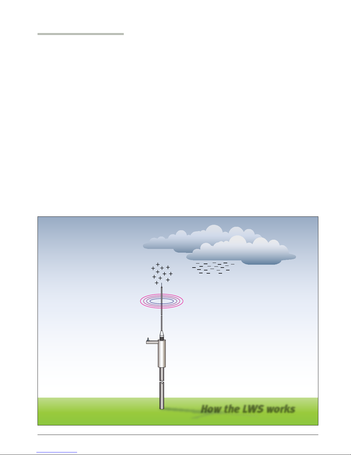
What does it do?
On detection of a nearby lightning event or significant increase in the electrostatic field, the system
will provide a Warning or Alarm to personnel that an event has occurred or is likely to occur. Detection
and Alarm Indication (via a siren) is performed by the sensor unit, with results being sent wirelessly to
the console for more detailed event Indication and logging.
Whip antenna detects
electric discharges due
to lightning activi
Storm Cell
Corona point
detects increase
in electric field
strength as a
result of:
• approaching storm
• storm cell overhead
LPI
Sensor
Assembly
How the LWS works
Page 7

Document 36 II LWS-MKIII, pub V5 © Copyright 2012 LPI Page 5
Console
The LWS MkIII Console provides the user interface to the LWS via its Webserver. It communicates with
the sensor providing the user access to current lightning information.
This information includes details such as the current Lightning Warning Level, and recent lightning
related activity such as Lightning Strikes and Electric Field Levels.
The Console is typically sited in a secure location where it can either be connected directly to a
computer by cross-over Ethernet cable, or by straight-through Ethernet cable to a local network,
allowing the user to access the relevant data and system settings. The Console has relay outputs for
Alarm, Warning and All Clear indications suitable for switching contacts (Note: Only a small amount
of current can be supplied by the Console alarm relay outputs, and therefore a siren or other indicator
cannot be driven directly from the outputs).
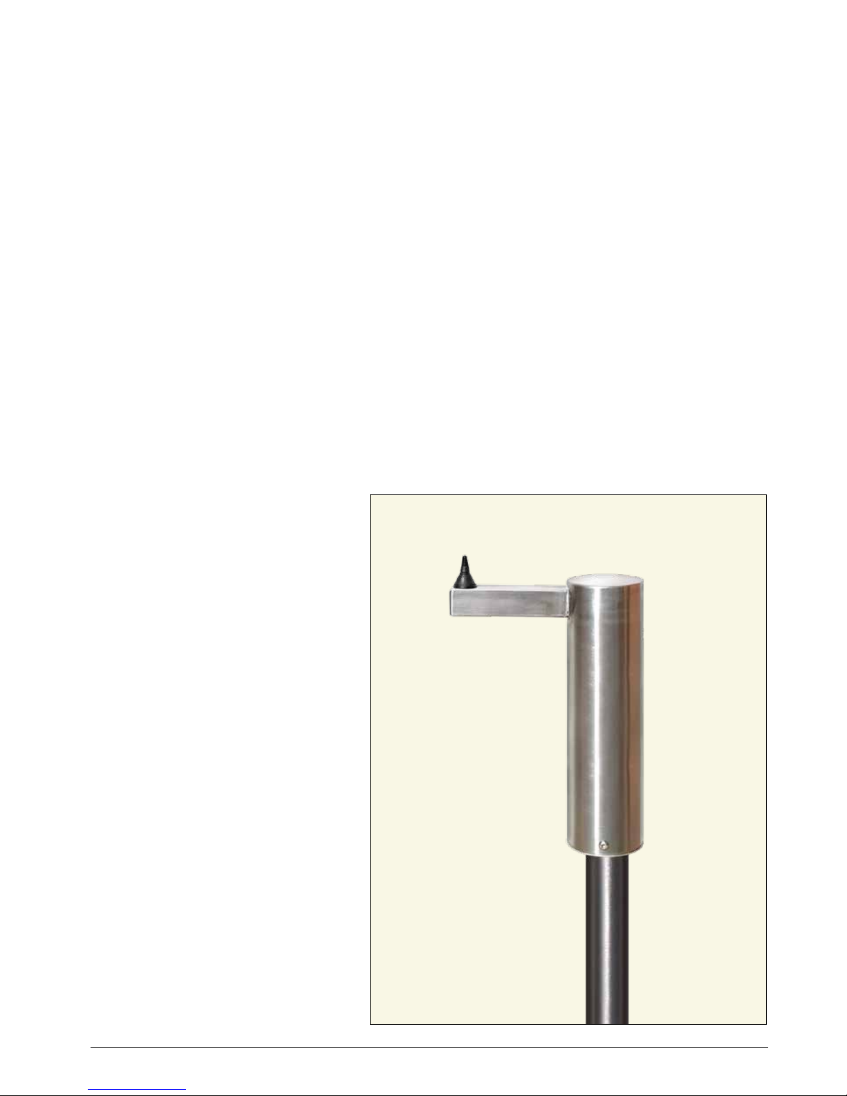
LWS Sensor Assembly
The LWS Sensor Assembly (Microprocessor, Sensing Antenna, Alarm/Warning/All Clear Indicator and
Earth Rod) is the integral component of the LWS system, it provides all decision making in regards to
recorded lightning events and subsequent alerts.
The LWS Sensor Assembly is typically mounted at a suitable location at site and the monitoring of all
lightning activity is controlled by an on board microprocessor. This works in conjunction with the sensing
antenna to detect changes in the electric field and approaching lightning discharges. Depending on
the intensity of the electric field or proximity of the lightning, the sensor provides an event indication
via wireless communication to a receiving antenna and console unit which is positioned within 1 km
line of sight of the sensor.
Each sensor also contains an Alarm/Warning/All Clear Indication device. Depending on customer
preference this is provided by a siren, which allows the user to communicate situation events
to all personnel in accordance with site safety policies and procedures. In the event of temporary
communication loss between the Console and Sensor, indication of event detection still occurs at the
sensor despite the communications loss.
Depending on the layout of the site and the area to be monitored, LPI can customize a solution.
LPI can also provide a suitable Mounting Pole (OD 70mm, ID 61.5mm) to mount the LWS Sensor
Assembly to. If the Mounting Pole option is included, suitable locking bolts are also provided to keep
the LWS Sensor Assembly secure.
Event Indication Levels
As the LWS MkIII sensor detects lightning activity or increases in the electric field, event indications
are made at the Sensor and are communicated to the Console for processing. If the event falls within
a predetermined level, the following indications are provided to the user.
Page 8

Page 6 Document 36 II LWS-MKIII, pub V5 © Copyright 2012 LPI
LPI
Sensor
Assembly
Established
storm front
• LWS activates warning when
lightning is within 10 -25 km
• Typically 20-30 minutes warning
• External siren can be sounded
if required
10 - 25 km
Warning Status
Warning Indication
A Warning Indication occurs when either a far lightning strike or a low electric field is detected. Far
lightning strikes are defined as lightning events that occur within a radius of approximately 10 to 25km
of the sensor. Low electric-field events are defined as being when the local electric field rises above a
level of 3kV/m. A Warning status provides the user with an indication that a storm is within a relatively
close range and may move towards the area where the sensors are stationed. When a storm is within
25km it may arrive in the area in approximately 20-40 minutes.
Page 9
Document 36 II LWS-MKIII, pub V5 © Copyright 2012 LPI Page 7
LPI
Sensor
Assembly
• LWS activates alarm when
lightning is within 8 -10 km
• Storm 10 -15 minutes away
• External alarm (siren) sounds
warning of impending danger
8 -10 km
Alarm Status
Established
storm front
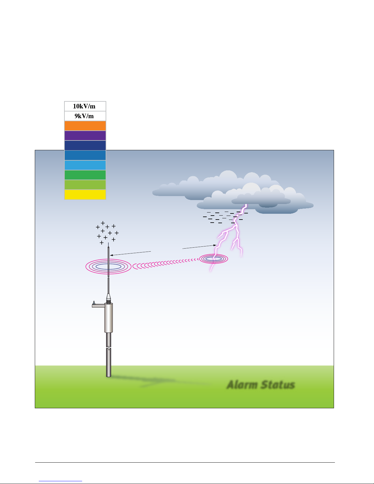
Alarm Indication
An Alarm Indication occurs when a near lightning strike or high electric field is detected. Near lightning
strikes are defined as those being within a radius of approximately 8 to 10km of the sensor and could
be close enough to pose a significant risk within approximately 10-15 minutes. High electric field events
are defined as being when the local electric field rises above 7kV/m. An Alarm status provides to the
user an indication that current activities at site should be suspended and shelter taken in accordance
with established safety procedures.
Page 10
Page 8 Document 36 II LWS-MKIII, pub V5 © Copyright 2012 LPI
All Clear Indication
An All Clear Indication is given when no activity (far strikes, near strikes, low electric field or
high electric field) has occurred within 10-30 minutes (programmable). After this period of no activity
it is deemed safe to resume all activities.
*There is also a Quick All Clear version of the LWS, which will behave slightly differently, this will give
an all clear indication after 10-30 minutes with no Near Strikes or High E fields.
Optional Range Extenders
In a standard LWS MkIII system, the Sensor must be within 1km and have direct line of sight to the
Console Communication Antenna. If this is not possible, then important information about settings
and recorded lightning events will not be transmitted.
However it is possible to use one or more Range Extenders to increase the distance between the
Sensor location and the Console, allowing settings and lightning event information to be passed
between the Sensor and Console.
Range Extenders work by being placed in positions that give <1km line of sight to both the Console
Communication Antenna and the Sensor (or to another interim Range Extender).
Range Extenders can also be
configured to act as alarm repeaters,
turning on alarms at the same time
as the Main Sensor and Console.
This allows a greater area to receive
warnings about lightning events.
Range Extenders have no individual
capability for detecting lightning
events.
Up to 10 Range Extenders can be
included as part of a system. These
can be arranged in a mesh or line
configuration. It is possible to have
more than 1 Range Extender within
<1km line of sight of another Range
Extender, Sensor or Console without
interference.
Range Extenders are available in
either Package A (power supply)
or Package B (solar panel)
configuration.
Page 11
Document 36 II LWS-MKIII, pub V5 © Copyright 2012 LPI Page 9
Installation
Console Installation
The console should be situated in a secure location close to either the primary computer used to
access the user interface, or to a router/network switch to allow for easy connection. This location
should allow for a co-axial antenna cable to be connected to an “out-door” wireless antenna. The
length of co-axial cable supplied is 2.5m long. The out-door antenna must also have line of sight to a
sensor within a range of 1km. For multiple sensor systems the console antenna only requires line of
sight to the nearest sensor less than 1km away.
A recent web browser, such as Firefox, Chrome or Internet Explorer, must be installed on a
connected computer to view the web based user interface. Elements of the user interface may not
work correctly using an old browser.
The console requires a 6Vdc power supply, the power supply is included and comes with an
Australian 3pin to IEC C7. mains lead.
If required the customer is to supply
an IEC C7 mains lead to suit their local
mains power socket outlet type.
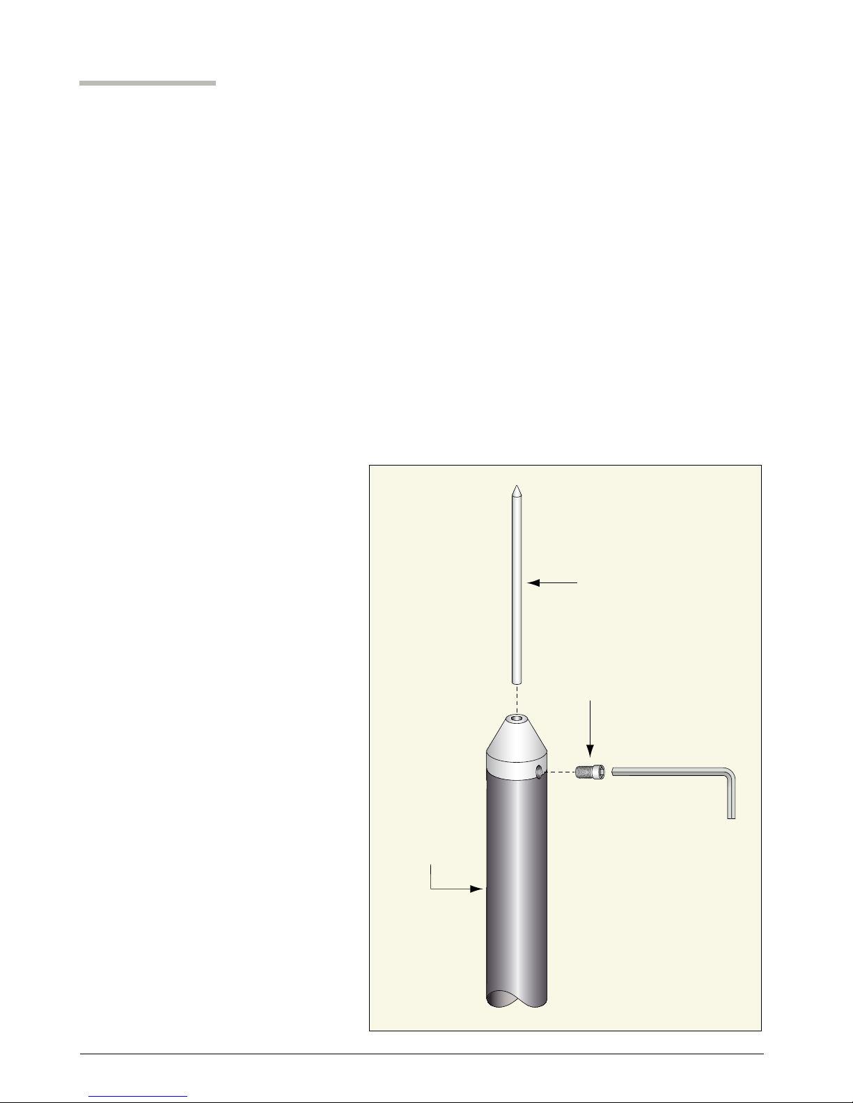
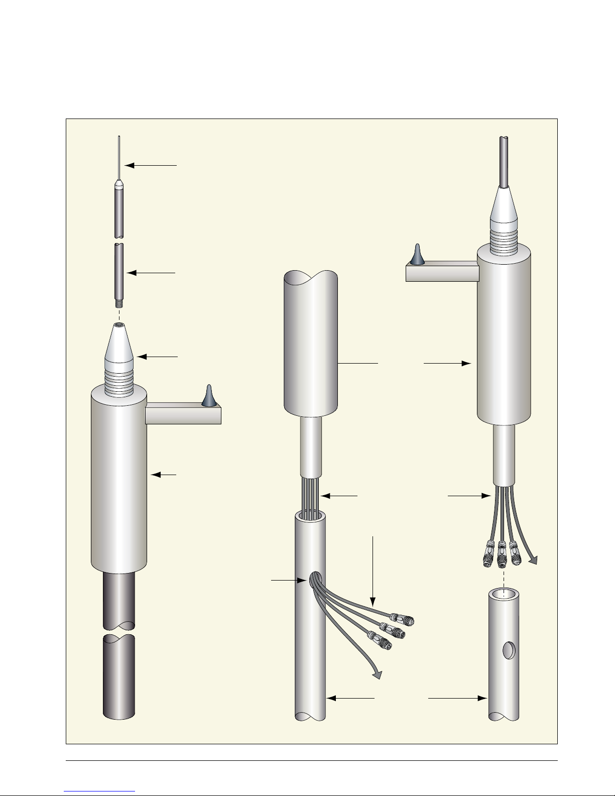
Corona Point Needle
Grub Screw
Upper
Sensor
Antenna
Sensor Installation
The Sensor Assembly will be provided
in three separate parts; the upper
sensor antenna, the sensor housing
and copper earth rod. In an approved
location (see section on Approved
Sensor Locations), the procedure for
Assembly of the Sensor Assembly is
as follows:
i) Insert the Corona Point Needle
into the top of the upper sensor
antenna and secure in place with
the provided grub screw and hex
key.
Page 12
Page 10 Document 36 II LWS-MKIII, pub V5 © Copyright 2012 LPI
ii) Screw the upper sensor antenna into the antenna base on the top of the sensor housing.
iii) Ensure cabling for Alarm relay outputs (siren/ LED display), power input (12Vdc plug pack
Solar Panel and Battery) and earth cable have been installed correctly, either up the centre of
the mounting pole or through a hole in the side of the mounting pole.
Cabling for Alarm
Relay Outputs
(Siren/LED Display),
Power Input
(12Vdc plug pack/
Solar Panel,
Battery) and
Earth Rod
Sensor
Housing
To Earth Rod
40 mm ø
minimum
Corona
Point
Needle
Upper
Sensor
Antenna
Antenna
Base
Sensor
Housing
Mounting
Pole
Page 13
Document 36 II LWS-MKIII, pub V5 © Copyright 2012 LPI Page 11
iv) Connect Alarm relay plug and socket and power input plug and socket.
Note: Ensure the supplied dust cap remains fitted to the remaining 7 pin plug (if not being used).
7 Pin Socket (Female)
To Alarm
4 Pin Plug (Male)
From Sensor
4 Pin Socket (Female)
From Power Supply
7 Pin Socket (Female)
Warning output from Sensor
(supplied with fitted dust cap)
7 Pin Plug (Male)
Alarm output from Sensor
Page 14
Page 12 Document 36 II LWS-MKIII, pub V5 © Copyright 2012 LPI
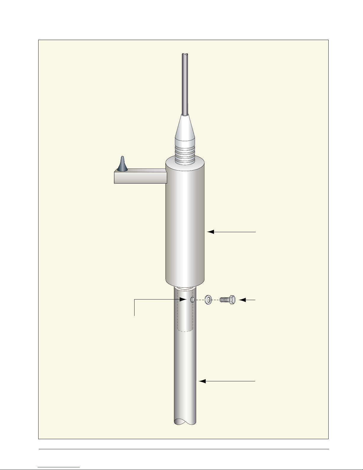
v) Attach sensor housing to the mounting pole.
LPI Mounting Pole
Securing Bolt
Sensor Housing
Holes are provided in the LPI supplied
Mounting Mast. Fit two securing bolts
to lock the Sensor to the mast.
Page 15
Document 36 II LWS-MKIII, pub V5 © Copyright 2012 LPI Page 13
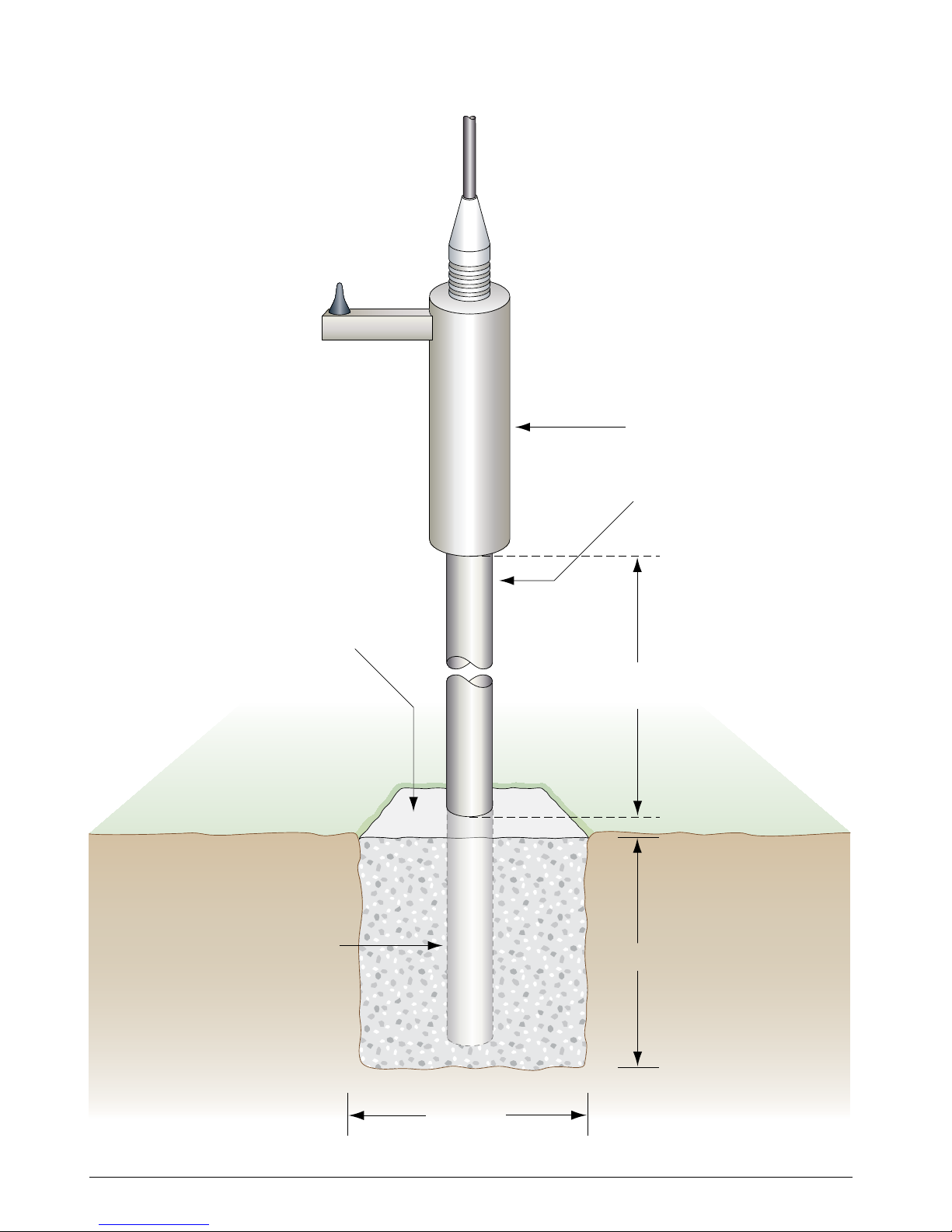
LPI Mounting Pole
Concrete
and gravel fill
Sensor Housing
600 mm
LPI Mounting Mast
600 mm
Minimum Height
2 m
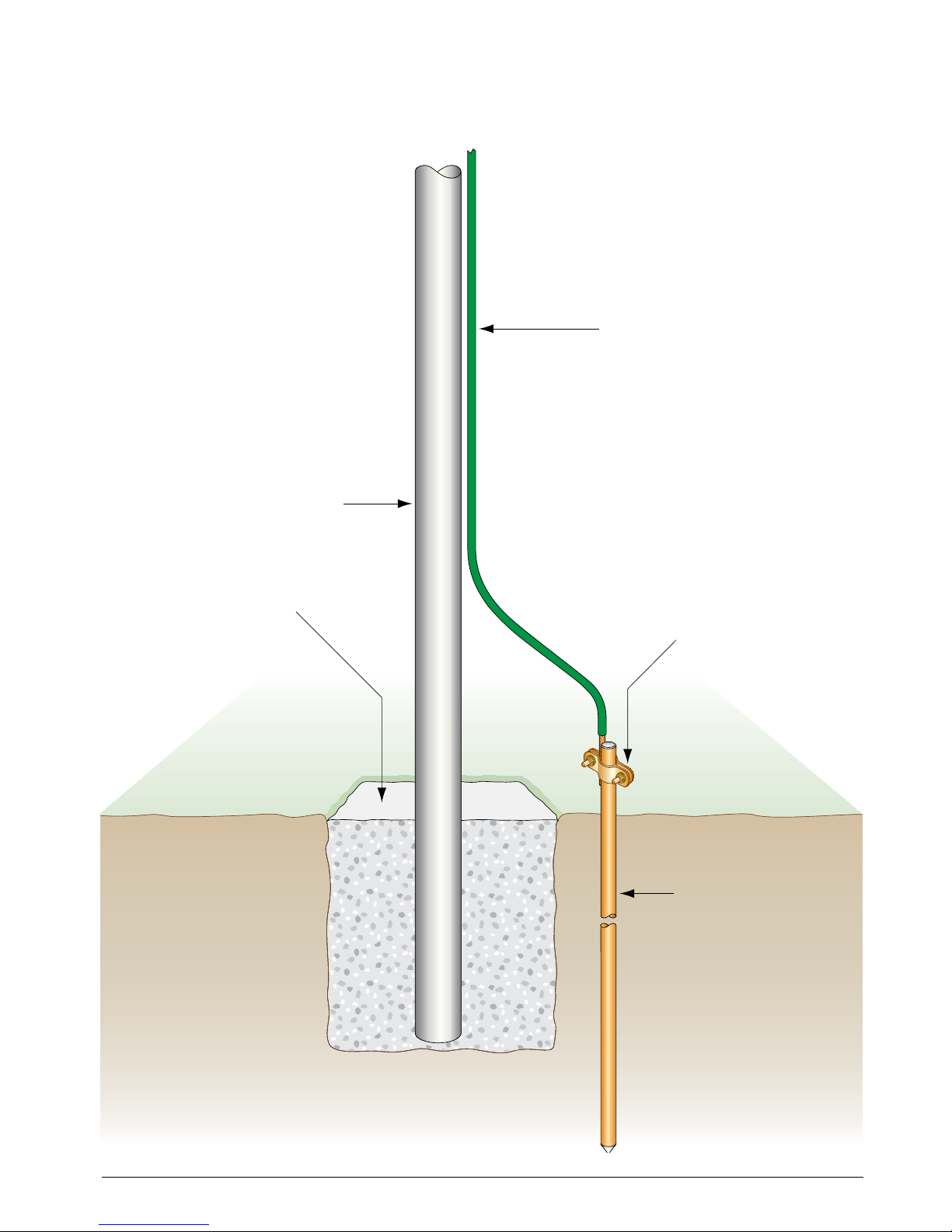
vi) Securely place a mounting pole in the ground (recommended depth of at least 600mm with
concrete and gravel fill).
Page 16
Page 14 Document 36 II LWS-MKIII, pub V5 © Copyright 2012 LPI
Earth Wire from
Sensor Assembly
Rod Clamp
LPI Mounting Pole
Earth Rod
Concrete
and gravel fill
vii) Drive the earth rod into the ground beside the Sensor Assembly and clamp the grounding cable
(from the Sensor Assembly or from the 4 pin connector, see “Relay/Alarm Output and Power
Connectors” section for details, page 44) to the rod using the rod clamp provided.
Page 17
Document 36 II LWS-MKIII, pub V5 © Copyright 2012 LPI Page 15
LWS Sensor
Mounting Pole
4 Pin Female Plug
from Power Supply
4 Pin Male Plug
from Sensor
110 - 240V AC Mains
Power
Power Supply
Customer
supplied and fitted Mains cable
Weatherproof
Enclosure
viii) Ensure that the selected power supply and Alarm Indication device is connected correctly.
ix) If supplied, mount the solar panel assembly (with battery) on the mounting pole. To achieve
maximum battery charging, the solar panel should be aligned so that it faces towards the sun.
For locations in the Southern hemisphere the panel should face North, in the Northern
hemisphere the panel should face South. Ensure that the solar panel is not in the shadow of
the mast at any time during the day.
Page 18

Page 16 Document 36 II LWS-MKIII, pub V5 © Copyright 2012 LPI
7 Pin Male Plug
7 Pin Female Plug
Alarm Siren
Mounting Pole
40 mm ø minimum
Mount Siren to
Mounting Pole
Page 19

Document 36 II LWS-MKIII, pub V5 © Copyright 2012 LPI Page 17
Mounting Pole
To Earth
7 Pin Socket
7 Pin Socket with
End Cap
7 Pin Plug
4 Pin Socket4 Pin Plug
Battery Box
mounted to
Mounting Pole
LWS Sensor
LWS Antenna
Solar
Panel
Adjustable bracket
to allow Solar Panel
to face the sun
(seasonal)
Mount Solar Panel
to LWS Mounting Pole
Optional Battery Box Sun
Shade. Not supplied with
LWS. If required, can be
manufactured by customer.
Siren
Page 20

Page 18 Document 36 II LWS-MKIII, pub V5 © Copyright 2012 LPI
Coaxial Cable
(Max. length 2.5m)
Console
Network
Switch
Ethernet
Cable
PC
Monitor
Antenna
10 mm ø
Hole for
Cable
x) The battery and circuitry in the power supply / battery box should be kept below 43 degrees
Celsius at all times. Direct sun on a hot day will take the power supply box over this level. So If
there is any possibility of this temperature being reached then shade must be provided for the
power supply box. The shade must not restrict airflow around the box. See previous diagram.
For further advice on deployment in difficult conditions please contact LPI.
Once the Sensor Assembly has been configured and both the Alarm Indication device and
power supply are connected, the sensor will run through a “Power-On-Self-Test”. This tests
that the relay outputs are functioning correctly (an Alarm, Warning and All Clear Indication
should be seen/heard briefly when alarm output is enabled). After approximately 30 seconds of
operation without another “Power-On-Self-Test” the sensor is functioning correctly and ready for
operation.
A mounting pole can be supplied by LPI as an optional extra if required. Any mounting pole supplied
by the client must be 2-3m long to provide correct calibration height, and have a minimum internal
diameter of 61.5mm.
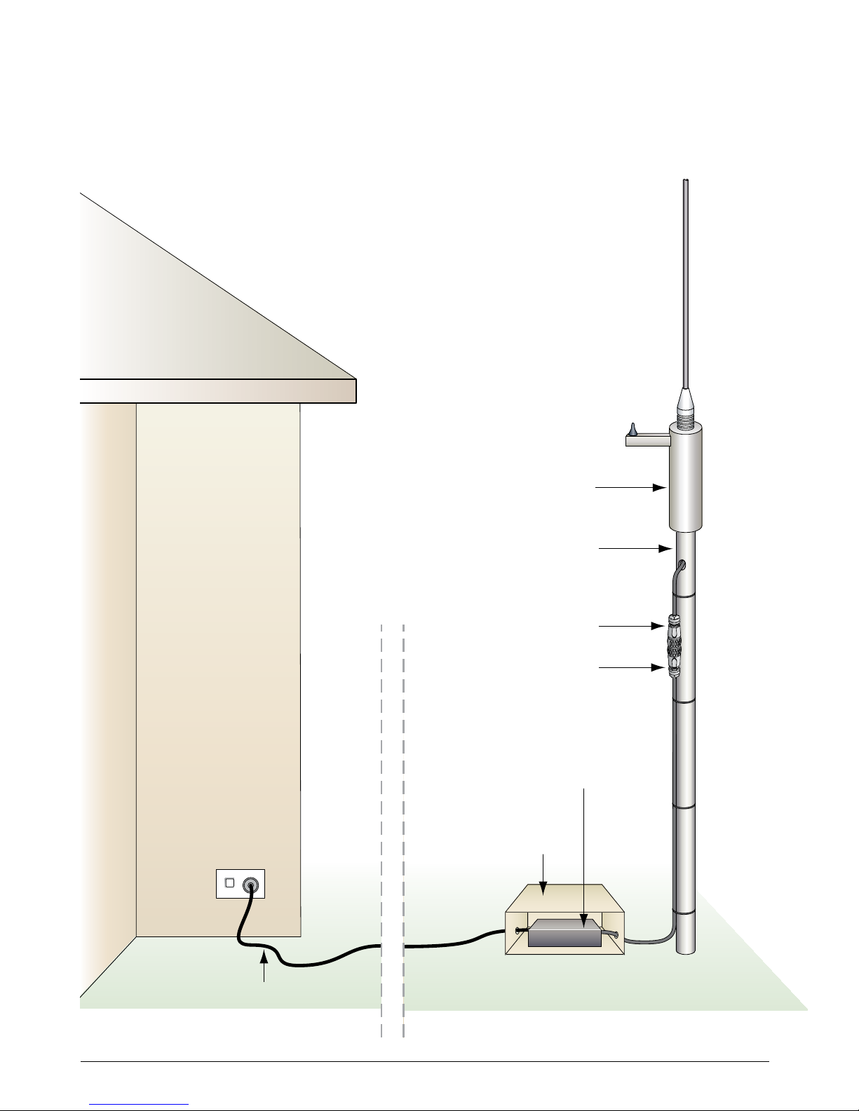
Installation of Console / Console Antenna
The Console should be placed within approximately 2m of where the Console Antenna is to be mounted.
The supplied cable length is 2.5m between the Console and the Console Antenna. The console should
also be positioned within a suitable distance to a power point. An Ethernet Cable with a length of up to
50m can be used to connect the Console to a Network Switch or dedicated computer.
Once Console and Antenna have been installed in a suitable location, connect the Coaxial Antenna
Cable to the Coaxial Flying Lead on the Console. The Console Antenna may be mounted inside building
if close to a window and retains line of sight to nearest sensor or Range Extender.
Page 21

Document 36 II LWS-MKIII, pub V5 © Copyright 2012 LPI Page 19
Antenna
8 mm ø Bolt Holes
Cable Gland
Coaxial Cable
LWS Console
Ethernet
Port
Relay
Contacts
(optional)
Restore
Defaults
Power
LED
Coaxial
Antenna Cable
110-240V Mains Power
6V DC Power Supply
Figure 8 IEC
Input (110-240V AC)
Customer supplied
IEC C7 Mains lead
Page 22
Page 20 Document 36 II LWS-MKIII, pub V5 © Copyright 2012 LPI
7m
7m
7m
10m
20m
7mExclusionZone
~27m
7m
~4m
1.5m
40m
30m
15m
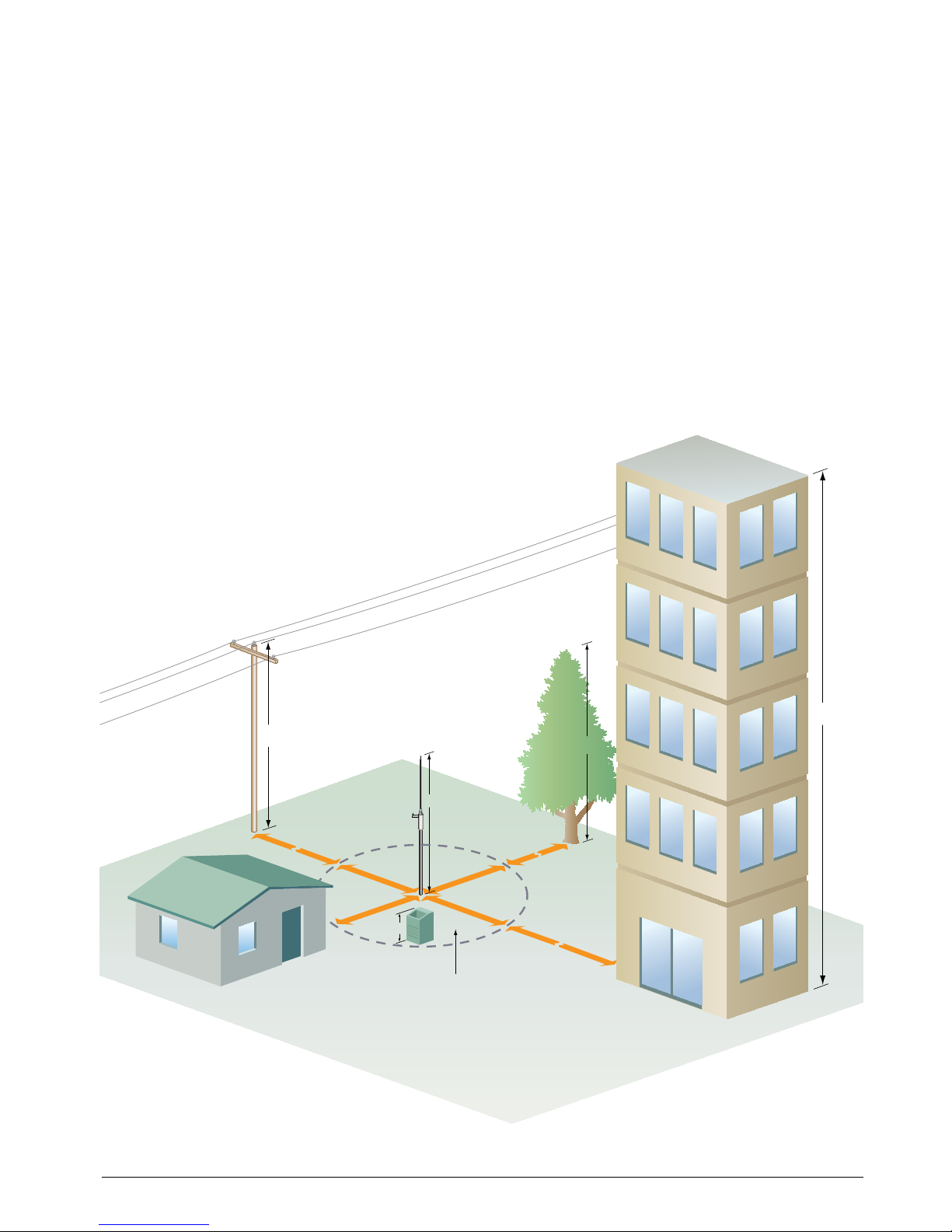
Approved Sensor Locations
To ensure correct operation of the LPI LWS MkIII, the following requirements for possible Sensor
locations must be adhered to:
i) For single Sensor systems the Sensor Assembly location must be within 1km of the Console
antenna with direct line of sight between the two wireless antennas.
ii) Sensor Assemblies must be located on “flat” (some elevation is acceptable) ground. Installing
the Sensor on raised ground or on any structure or building will increase the electrostatic
intensification at the tip of the Sensor antenna, therefore giving false e-field readings and alarms.
iii) A minimum distance of 7m between the Sensor Assembly and any nearby structure or trees. Tall
objects close to the Sensor will have a shielding effect on the measured e-field at the tip of the
Sensor antenna, therefore giving false e-field readings.
Page 23

Document 36 II LWS-MKIII, pub V5 © Copyright 2012 LPI Page 21
iv) The Sensor Assembly should not be placed under or within 7m of power or telephone wires.
v) Height of objects within 7m of the sensor should be at most 1.5m tall.
vi) Minimum 7m distance applies to objects with a height comparable to the sensor, taller objects
will need to be further away to prevent shielding of the sensor. Recommended distance is 2/3
the height of the object in addition to the 7m separation.
The Sensor should only be installed in locations conforming to the “Approved Sensor Locations”
requirements.
Range Extender Installation
As Range Extenders do not have any lightning event
detection capability they are not subject to the same
location restrictions as Sensors. Range Extenders will need
to be placed in positions that allow <1km line of sight to the
Console, Sensor or another Range Extender.
Cabling installation, Alarm relay plug and socket, mounting,
power supply, siren and solar panel installation instructions
are as shown in Sensor Installation points iii (without sensing
antenna or earthing cable), iv, v, viii and ix respectively.
Page 24

Page 22 Document 36 II LWS-MKIII, pub V5 © Copyright 2012 LPI
Operation
Accessing the Interface homepage
To start using the LWS Connect the console to power. Connect the out-door wireless antenna, to the
console by screwing the antenna cable in. Connect the provided cross-over Ethernet cable to the LWS
and to your computer.
Ensure that your computer has an IP Address of 192.168.1.1 (or similar) and a subnet mask of
255.255.255.0. If you need further information please refer to section “Establishing a LAN Connection
to the LWS Console”
Open an approved web browser (Microsoft Internet Explorer, Mozilla Firefox or Google Chrome)
and type Into the address box, the address 192.168.1.90. Once the Home page is accessed the IP
of the console can be changed in the “IP address” button, this can be found by clicking on the
“Settings” link.
To reset the Console default IP Address settings, see the section entitled “Restoring Console
Factory Default Values”.
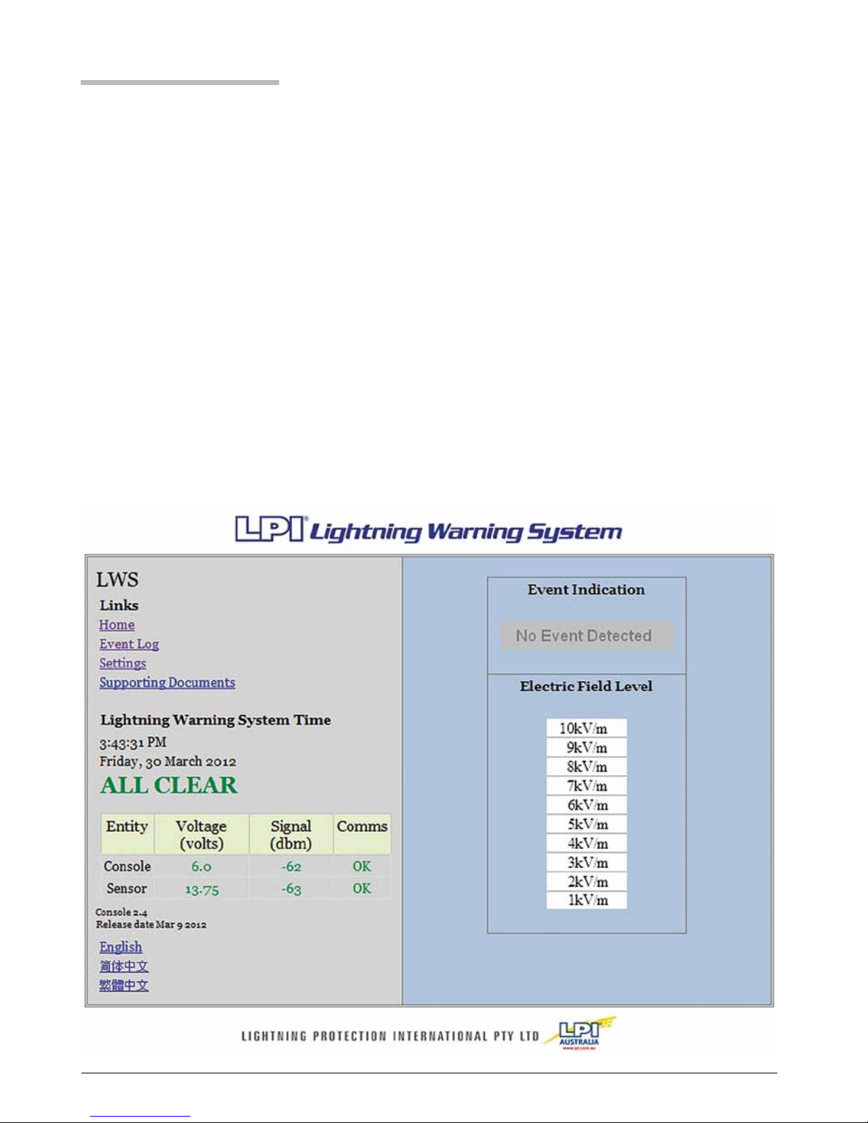
The Home page provides the basic system information to the user. It shows:
• The current Electric-Field being measured in the form of Graphs (0-10kV/m).
• The current Lightning Warning System Time and Date (see “Changing the Settings: Time and
Date” for more information). If the colour of the time is red then your PC time is different to your
LWS time. If the times are different they should be changed to the correct local time.
• The status of the Sensor and Range Extender batteries (if connected and only if it is flat).
• If a Lightning event has been detected.
• A series of links to other sections of the web user interface.
• Current Alarm State (All Clear, Warning or Alarm)
Page 25

Document 36 II LWS-MKIII, pub V5 © Copyright 2012 LPI Page 23
Event Log
By clicking on the “Event Log” the user will be directed to a page displaying the log of previous events.
A maximum of 150 different events will be stored in the Log (above this number new events will
overwrite old events).
Log entries are broken into three parts:
• the type of event,
• the unit which recorded the event, this is MA for Master and RE for a range extender,
• the time and date at which the event was recorded.
There are several different event types which may be seen in the Log window. Types include:
• Far Strike, the sensor recorded a far strike.
• Near Strike, the sensor recorded a near strike.
• E Field High, the sensor recorded a high electric field.
• E Field Low, the sensor recorded a low electric field.
Page 26

Page 24 Document 36 II LWS-MKIII, pub V5 © Copyright 2012 LPI
• All Clear, the event timer on the sensor timed-out and there is now no lightning activity within
the detection range.
• Found MA, the sensor regained communications with the console after a communication time-out.
• Lost MA, the console has lost communications with the Master Sensor.
• Reset MA, the sensor experienced a power or timer reset.
• Low Batt *, the corresponding sensor or Range Extender has a low battery.
• Low RSSI *, the corresponding sensor or Range Extender has a low wireless signal strength.
The Log page also has option buttons Erase the event log (this should only be done if the current event
log is no longer required, data cannot be reinstated) and to save the currently displayed event log as
a text file.
Saving the current displayed event log as a text file works differently in both Internet Explorer and
Firefox.
Saving in Internet Explorer:
By pressing the “Save Event Log” button in IE, the user will be directed to a page displaying the text
file. To save the file go to the “page” menu, then click “save as” and save as a text file in the desired
location on the connected computer.
Note: earlier versions will be similar to Firefox method on the following page.
Page 27

Document 36 II LWS-MKIII, pub V5 © Copyright 2012 LPI Page 25
Saving in Firefox:
By pressing the “Save Event Log” button in Firefox, the user will be taken to a page displaying the file.
To save the file click on the “file” menu and then click “save page as”. The log text file can then be
saved in the desired location on the connected computer.
Page 28

Page 26 Document 36 II LWS-MKIII, pub V5 © Copyright 2012 LPI
Saving in Google Chrome
By pressing the “Save Event Log” button in Google Chrome. The user will be directed to a page
displaying the file. To save the file click on the “page” icon in the top right corner of the Google Chrome
browser and then click on “save page as”. The log text file can then be saved in the desired location
on the connected computer.
Page 29

Document 36 II LWS-MKIII, pub V5 © Copyright 2012 LPI Page 27
To access most of the setting pages a username and password is required each time a new browser
session is started (browser closed then opened again). The default username and password is
“admin” and “admin” respectively. The username and password can be changed in the Username/
Password page.
Changing the Settings
Page 30

Page 28 Document 36 II LWS-MKIII, pub V5 © Copyright 2012 LPI
Settings: IP Address
This page allows the user to change the IP Address, IP Mask, Gateway Address and DNS Address of
the console. The Address settings of the console can either be set by manually choosing preferred
values or by setting the console to automatically download Addresses from a local connected DHCP
server. When manually setting the Address if the IP Mask, Gateway Address and DNS Address remain
unchanged from a previous setup, then these fields may be left blank.
Note: Addresses assigned automatically by a DHCP server may change without warning if the console
or network router is restarted.
Refer to sections “Establishing a LAN Connection to the LWS Console” and “How to put LWS onto a
Network” for step-by-step guide on how to set-up the LWS Console so it can be accessed on your
Local Area Network.
Page 31

Document 36 II LWS-MKIII, pub V5 © Copyright 2012 LPI Page 29
Settings: Update Status
This page allows the user to check on the status and voltage of connected batteries. If Range Extenders
have been included in the system, a “battery flat” warning is displayed on this page when the Range
Extender battery is flat. This page is a display page only, no settings can be changed on this page.
Page 32

Page 30 Document 36 II LWS-MKIII, pub V5 © Copyright 2012 LPI
Settings: System Time
It is very important that the LWS time is set accurately to the local time.
This page allows the user to update the System Time of the LWS. Having a correct system time is
important for correlating observed lightning events with those recorded in the event log, and that the
alarms are enabled at the correct times.
There are two time and dates displayed on this page, one is from the computer connected to the
console (which is assumed to have the correct time) and the second is the current LWS time and date.
If these two time and dates are found to be different, then the system time can be set to the correct
time. A time difference of up to a minute is not a problem.
The “Refresh” button will preload the input boxes with the PC’s current local time. Pressing the “Set”
button will set the LWS time to the time loaded in the text boxes. This time will be sent to all elements
of the system.
Page 33

Document 36 II LWS-MKIII, pub V5 © Copyright 2012 LPI Page 31
Settings: System Status
This page is similar to the main page but has the addition of a Status Table.
The Status Table lists all the LWS Entities that are currently connected or have been connected to
the radio network. An entity can be either the Console or the Sensor or one of the range extenders (if
used). Each entity gives its Name , Voltage, Signal Strength and it’s communications status.
Sometimes some of the readings will be Red or Orange in colour, if these colours persist it indicates a
possible problem. If a voltage or signal strength reading goes red occasionally but comes back green
it is not a problem, just a missed packet. At startup the readings will all be Red for the first couple of
minutes. Don’t worry about this.
Generally the voltage should be above 11.3 volts, except for the console, which should be 6 volts.
Generally the signal strengths should be between -35db and - 85db. The closer the signal strength is
to zero the stronger it is.
Page 34

Page 32 Document 36 II LWS-MKIII, pub V5 © Copyright 2012 LPI
Settings: All Clear Time-out
This page allows the user to change the length of time between the last recorded lightning event
(Near/Far Strike, High/Low E-Field) and the All Clear Indication. The user has the option of choosing a
time between 10 minutes and 30 minutes before the All Clear Indication is enabled. After the settings
have been updated if the Current All Clear Time-out Period does not show the time which had just been
set, refresh the webpage. If the Time-out Period is still incorrect select the required time from the drop
down list again and allow system to update the settings.
The default All Clear Time-out is 15minutes.
Settings: Alarm Reassert
This page allows the user to reassert current alarm conditions by manually sounding the siren. It can
also be used to test the sirens.
If the LWS is in Warning or Alarm condition, then the user cannot assert an All Clear or a lower level
condition. If this is the case the button will not be visible to do this. The reason for this is for safety.
To test the Siren outputs the User will have to wait for the All Clear condition first.
Page 35

Document 36 II LWS-MKIII, pub V5 © Copyright 2012 LPI Page 33
Settings: Indication Duration
This page allows the user to change the length of time for Alarm, Warning and All Clear Indications
to occur for. The user has the option of choosing a time (between 5 seconds and 60 seconds) to have
indications enabled for. After the settings have been updated, the Current Indication Duration should
show the time which had just been set, if not then refresh the webpage. If the Duration is still incorrect
select the required time from the drop down list again and allow system to update the settings.
The default Indication Duration is 10 Seconds.
Page 36

Page 34 Document 36 II LWS-MKIII, pub V5 © Copyright 2012 LPI
Settings: Alarm Enable Times
This page allows the user to change the time at which Alarm (Warning and All Clear) Indications are
enabled and disabled, so that if lightning events occur during a time when the area is not in use there
will be no unnecessary alarms. Both on and off times are set by simply inputting the required times
and pressing the set button.
Note: All times should be entered in 24 hour format to ensure correct operation. The system will not
process an AM or PM time correctly. The on time must be before the off time.
Please note that it is very important to set the Alarm Enable Times correctly.
Page 37

Document 36 II LWS-MKIII, pub V5 © Copyright 2012 LPI Page 35
Changing the Settings: All Clear Mode
Sometimes an LWS is in Alarm condition at the time the alarms are disabled. ( By the Alarm Enable
Times). This means that an Alarm has sounded but no corresponding All Clear has been given.
When this is the case there are three options here to do with how to sound the All Clear.
You must choose one option.
• All Clear Force: sound the All Clear at the time the Alarms are disabled, this will mean an All Clear
is given even though the LWS is not in all clear.
• All Clear Allow: sound the All Clear at the Normal time even though this will be when the Alarms
are disabled.
• All Clear Normal: don’t sound the All Clear for this alarm, because it would be outside the Alarm
Enable times.
Page 38

Page 36 Document 36 II LWS-MKIII, pub V5 © Copyright 2012 LPI
Changing the Settings: Username and Password
This page allows the user to set the username and password for accessing the individual settings
pages. The username and password can be set to any string of characters, 10 characters or less. Both
the username and password are case sensitive. Once a new username and password has been entered
the user will be required to enter these before being able to access any settings pages.
If the Console is restored to factory defaults or no specific username and password have yet been set,
the username and password will be “admin” and “admin” respectively.
Page 39

Document 36 II LWS-MKIII, pub V5 © Copyright 2012 LPI Page 37
After automatically restarting, the Console will have regained the following default values:
• Alarm Duration: 10secs.
• All Clear Timeout Period: 15mins
• All Clear Mode: Normal
• Console IP Address: 192.168.1.90
• Console IP Mask: 255.255.255.0
• Gateway Address: 0.0.0.0
• DNS Address: 0.0.0.0
• Alarm Enable On Time : 07:30:00
• Alarm Enable Off Time : 18:30:00
• Username : admin
• Password : admin
Power
Cord
Relay Contacts
(optional)
Power On LED
Ethernet Cable
LWS Console
Ethernet Port
Restore Defaults
Coaxial
Antenna Cable
Restoring Console Factory Default Values
Before restoring the LWS to factory default settings you should try to ensure that the LWS console, the
Sensor and all the range extenders are communicating.
To restore the LWS to factory default values, use a paper clip or similar object to press the factory
default reset button.
When the button is pressed the red “Power On” led will initially turn off. Keep the button pressed until
the led starts flashing, this will take 3 seconds. The LWS will now reboot with the default settings.
If the button is released before the Power On LED starts flashing the LWS will do nothing.
Note: After restoring the factory defaults, the
Console IP Address settings will need to be
changed to allow connectivity to a connected
computer, or via a local network. Also please
set all values manually to your required
settings.
Page 40

Page 38 Document 36 II LWS-MKIII, pub V5 © Copyright 2012 LPI
Introduction
To communicate with the LWS you also need a personal computer, tablet or smartphone.
Communication needs to be established between your device and the LWS, at least partially through
a wired LAN (local area network).
It is also possible to establish communication through a hybrid wired/wireless LAN too.
There are three basic ways to set up the networking between the LWS console and a host computer.
1. A peer to peer network with Static IP addresses. Use crossover Ethernet Cable( Normally red or
black).
2. With the LWS as a static IP Address on a larger existing LAN. Use Straight Through Ethernet
Cable (normally blue).
3. With the LWS as a dynamic IP Address on a larger existing LAN. Use Straight Through Ethernet
Cable( Normally blue).
If you have an existing wired LAN and you wish to add the LWS to it you will have to work in cooperation with your network administrator.
You can contact LPI and they can email you a windows program to make it easy to set up the LWS on
your network.
Alternatively you can initially set up the communications as a peer to peer network, and then change
the configuration once communication is established.
Setting up a direct connection network for the LWS using Windows 7
All networked computers have what is known as an IP Address.
The LWS console has as a default address out of the factory, which is 192.168.1.90
The LWS console has as a default address mask out of the factory, which is 255.255.255.0
To set up a direct connection network you need to set up your PC to have a static IP Address of
192.168.1.1 and an Address Mask 255.255.255.0.
These settings will enable communication.
Establishing a LAN Connection to the LWS Console
Page 41

Document 36 II LWS-MKIII, pub V5 © Copyright 2012 LPI Page 39
Step 1.
Start Windows Explorer (not Internet Explorer)
This can be done in many ways, here is one:
• Click on the Start button at the bottom left of the screen.
• Directly above the start button is a text box, type in the word “explore”
• At the top should be a link to “Windows Explorer”, click on it.
Page 42

Page 40 Document 36 II LWS-MKIII, pub V5 © Copyright 2012 LPI
Step 2.
Open the Networking And Sharing Center
This can be done in many ways, here is one:
• Type in the path in the diagram.
• Press the “Enter” key.
Step 3.
Click on the link marked “Local Area Connection”
Page 43

Document 36 II LWS-MKIII, pub V5 © Copyright 2012 LPI Page 41
Step 4.
In the page name Local Area Connection Status, Click on the button marked “Properties”
Page 44

Page 42 Document 36 II LWS-MKIII, pub V5 © Copyright 2012 LPI
Step 5.
In the page name Local Area Connection Properties,
Select the line marked “Internet Protocol Version 4(TCP/IPv4)”
Then click on the button marked “Properties”
Page 45

Document 36 II LWS-MKIII, pub V5 © Copyright 2012 LPI Page 43
Step 6.
In the page Internet Protocol Version 4(TCP/IPv4) properties”,
Select the radio button marked “Use the following IP address”
Type in the address 192.168.1.1
Type in the subnet mask 255.255.255.0
Click Ok.
Page 46

Page 44 Document 36 II LWS-MKIII, pub V5 © Copyright 2012 LPI
Step 7:
Disconnect your computer from the network and connect to the Console using the black cross-over
Ethernet cable supplied with the LWS MkIII Console.
Step 8:
Your computer has now been assigned the IP Address of 192.168.1.1 and can now access the LWS
console in a Firefox or Internet Explorer web-browser by entering the address 192.168.1.90 into the
address bar. You will now be able to access the Settings Page of the Console.
The page should render like the diagram.
At this point you should have established communication with the LWS via a direct connection.
Page 47

Document 36 II LWS-MKIII, pub V5 © Copyright 2012 LPI Page 45
To put the LWS on a Local Area Network (LAN) you will need some help from the Network
Administrator.
You will need to know whether the Administrator wants you to use a fixed IP address or use DHCP to
assign your network settings.
The easiest way to do this is use an IP setup tool that can be provided by LPI. Ask us and we can
email it to you. Otherwise follow the steps below.
Initially
Establish communications with the LWS, by following directions in the section named “Establishing a
LAN Connection to the LWS Console”.
If using DHCP follow these steps
Step 1
Browse the Settings Page
Step 2
Click button marked Enter Manual IP Address (Even for DHCP)
Step 3
Click button marked Automatic
Step 4
Connect LWS and your PC to the network using the Blue (straight through) network cables.
Step 5
Turn off LWS and wait a few seconds and then turn it back on.
Step 6
Get the network administrator to put your PC back on to the network.
Step 7
Ask your network administrator what address the LWS has been assigned and then browse to it.
Add this page to your favourites or bookmarks, so that other users can find it easily.
How to put LWS onto a Network
Page 48

Page 46 Document 36 II LWS-MKIII, pub V5 © Copyright 2012 LPI
Page 49

Document 36 II LWS-MKIII, pub V5 © Copyright 2012 LPI Page 47
General Browser Settings
Whether you are using Internet Explorer, Firefox, Safari or Chrome as your browser there are a couple
of settings that your browser needs to communicate successfully with the LWS. Javascript must be
turned on for this website. The character encoding should be UTF-8 or Auto-Detect.
These settings are generally turned on anyway so generally you don’t have to change anything here.
If using a Static IP follow these steps
Step 1
Browse the Settings Page
Step 2
Click button marked Enter Manual IP Address (Even for DHCP)
Step 3
Ask your network administrator what IP address to use and what IP mask to use.
Step 4
Insert the values given by the network administrator into the text boxes on the page.
You don’t need to worry about the Gateway and the DNS address, just leave them blank.
Step 5
Make sure the format has the full stops and double check they are correct.
Write down this address.
Step 6
Press the button marked Set.
Step 7
Connect LWS and your PC to the network using the Blue (straight through) network cables.
Step 8
Turn off LWS and wait a few seconds and then turn it back on.
Step 9
Get the network administrator to put your PC back on to the network.
Step 10
Browse to the address that you assigned to the LWS.
Add this page to your favourites or bookmarks, so that other users can find it easily.
Page 50

Page 48 Document 36 II LWS-MKIII, pub V5 © Copyright 2012 LPI
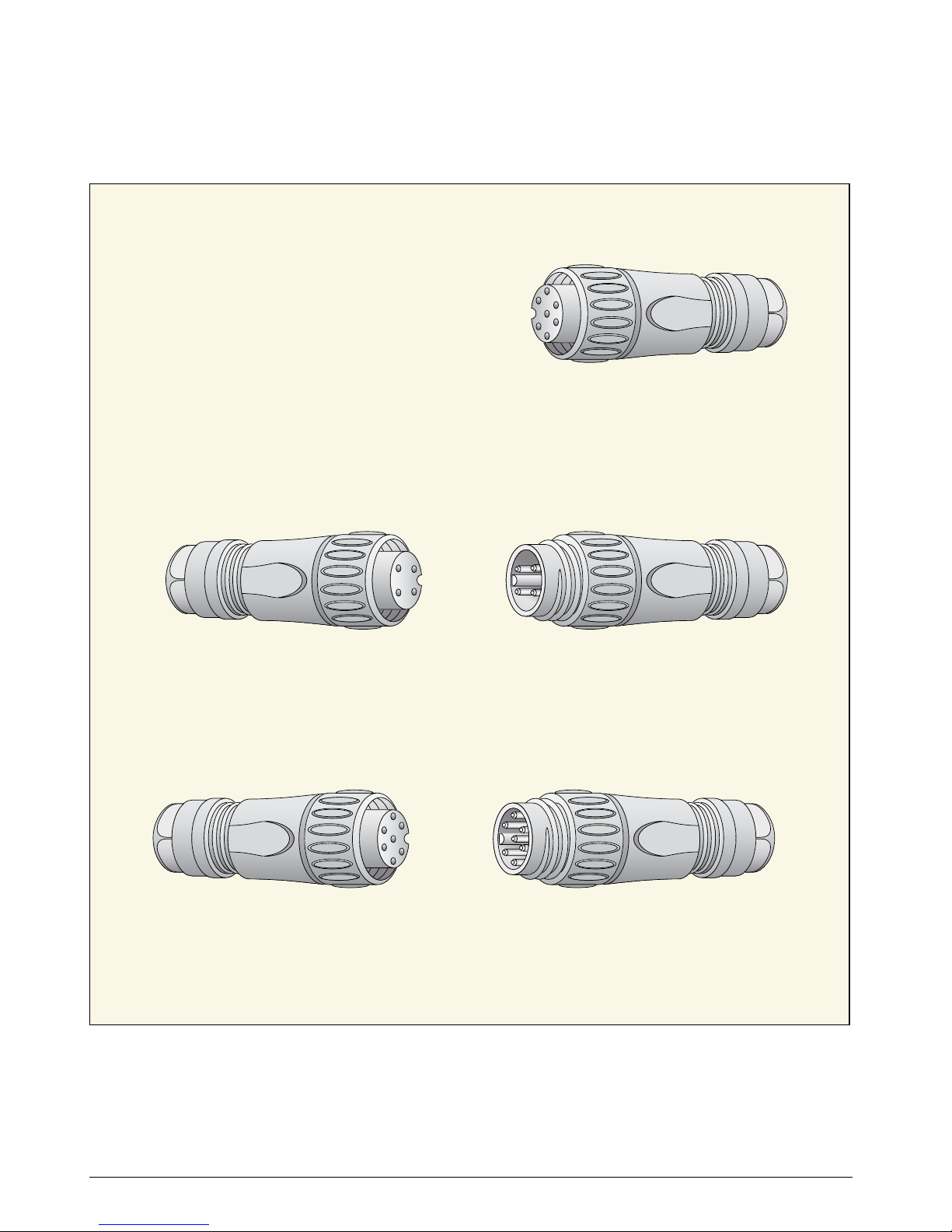
1=DC(-)
2=DC(+)
3=SOLAR(+)
4=DC(-)
1=DC(-)
2=DC(+)
3=WARNINGNO
4=WARNINGCOMMON
5=WARNINGNC
6=NotConnected
1=DC(-)
2=DC(+)
3=ALLCLEARNO
4=ALLCLEARCOMMON
5=ALARMNO
6=ALARMCOMMON
4 PIN MALE
7 PIN FEMALE (Covered)
Diagramsshowpin
connectionslooking
towardsfrontofplugs
Alarm Relay and Power Connectors (Sensor and Range Extennders)
Linked
2
1
3
4
NotConnected
4
5
6
3
2
1
NotConnected
3
2
1
4
5
6
7 PIN MALE (Siren Connector)
Note: All Sensor and Range Extender DC Outputs are 12V with maximum current of 250mA. Relays are capable of
switching 120Vac at up to 1A. Console Relays are capable of switching 120Vac at up to 1A.
Relay / Alarm Output and Power Connectors
The Pin Connections for Sensor Assembly
Plugs are as shown in the following diagram.
Page 51

Document 36 II LWS-MKIII, pub V5 © Copyright 2012 LPI Page 49
A maintenance check should be conducted every 3 months, if a communications error is displayed or
if the system is suspected of not recording obvious lightning events.
Sensors and Range Extenders
• Check for physical damage to exterior of Assembly.
• Check for physical damage to Cables (Power and Siren cables).
• For Sensors check for damage to electric field sensing needle at top of sensing antenna.
If damaged (bent) or missing please contact local LPI distributor for an approved replacement.
• For Sensors check that earth rod is still installed correctly and earth cable from Sensor is still
connected.
• Check condition of Fuse (Package A: inside power supply enclosure, Package B: inside battery
box).
• Disconnect and reconnect power to the Sensor/Range Extender.
Console
• Check Red power LED is on.
• Check that Communications Antenna has line of sight to the nearest Sensor or Range Extender.
• Check that the Ethernet Cable is correctly inserted in the Console Ethernet socket, and that the
Ethernet cable is still connected to a computer or network switch at the other end.
• Check that the green network lights are on, they indicate that the network cable is actually
connected to a network.
• In settings page re-confirm settings (e.g. System Time, Indication Duration, All Clear Time-out
Period and Alarm Enable Times).
• Test Alarm Sounding Operation (in Alarm Override page). Ensure that all personnel are aware of
imminent test before hand, to avoid unnecessary confusion.
Maintenance Check Recommendations
Page 52

Page 50 Document 36 II LWS-MKIII, pub V5 © Copyright 2012 LPI
Supporting Documents
Optional Extras
Links to a software copy of the Installation and Operating Manual, Technical Data Sheet and to the
Brochures (English and Chinese) can be accessed by browsing to “Supporting Documents” from the
Links list.
The documents have short names, here is an explanation of them.
LOG.TXT: Your log file.
INST&OP.PDF: The electronic version of the Installation and Operation Manual.
TDS.PDF: The Technical Data sheet for the LWS
BROCHCH.PDF: The Brochure for the LWS (chinese)
BROCHE.PDF The Brochure for the LWS (english)
• Wireless Range Extenders (with Alarm Relay Outputs), available in solar panel or power supply
configuration. (Maximum 10)
• Sirens for Range Extenders
• High powered/Industrial Siren
• Wired version of LWS. Communications between the Console and the Sensor are wired through a
coaxial cable instead of wirelessly. The upper range limit of this cable is about 50m. The wired
version does not allow for range extenders to be used with the system.
Page 53
Document 36 II LWS-MKIII, pub V5 © Copyright 2012 LPI Page 51
Troubleshooting
Checking Power
When power is initially connected to the Sensor or Range Extenders a “Power On Self Test” is
performed. Successful power on and start up is indicated by switching the Alarm Output Relays on in
sequence (Warning, Alarm, All Clear). If the Alarm Output Relays are not enabled this indicates a fault
has occurred with the Power Supply or with the Sensor or Range Extender itself. If this occurs check
that power is being supplied to the Sensor or Range Extender, if power is being supplied as expected
please contact your LPI distributor.
Checking Network
You should be able to browse to the console by going to a favourite or bookmark. That should have be
set up in “Establishing Connectivity to the LWS”.
If you can browse to this page then commincations between your PC and the LWS console are ok.
Checking Communications to Sensor
Browse to settings and then click the button marked System Status.
Check to see that all your LWS entities are listed, ie. Sensor, Console and each range extender.
Page 54

Page 52 Document 36 II LWS-MKIII, pub V5 © Copyright 2012 LPI
Check that communications to all units are listed as OK.
Check that all voltages except console are above 11.3 volts and are green. If this is not the case you
have to investigate why, possibly the solar panel is not charging. LPI can help you with this, please
contact us.
Check that all signal strengths are closer to zero than -85db.
If this is not the case you have to investigate why, it might be that something is blocking the radio
communications, the units may have to be repositioned. If the signal strength is between -85 and -105
db then communication may be intermittent.
If the voltages or the signal strengths occasionally go red but come back green or orange in a minute
or two, this is nothing to worry about, This happens occasionally it is just a packet dropout.
Checking Siren Functionality
In the situation of lightning events being detected, displayed and logged, but no Alarm or All Clear
sirens being sounded and no Alarms activated when using Alarm Reassert buttons, please check that
the System Time and Alarm Enable/Disable Times (see “Changing the Settings: System Time” and
“Changing the Settings: Alarm Enable Times”) are set correctly. If the Current system time is outside
the Alarm Enable Times then the Alarm Relay Outputs will not be activated (and therefore no Siren
Sounded). If problems still occur please contact your LPI Distributor.
Error Messages
If something does go wrong with the LWS and the console can’t communicate with the Sensor, then an
appropriate message is displayed, in RED, on the Home Page.
Please don’t ignore this but try to find the cause of the problem.
Possible causes of this type of problem is:
• a loss of power on the Sensor,
• a bad radio path to Sensor
• a loss of a critical range extender
• a broken or damaged antenna cable near the console.
If you can’t resolve the problem yourself contact you LPI distributor for assistance.
Page 55

Enclosure: Die-cast, 170mm (L) x 120mm (W) x 50mm (H)
Control: Micro Processor
Interface: Webpage (default address 192.168.1.90)
Operation: Console receives Electrostatic Field measurements and event
noticationfromsensorsintheeldanddisplaysreceived
informationonaneasytoreadwebpage.Allowsusersto
downloadandsavealogofeventsthathaveoccurred.Allows
userstochangearangeofsettings.
RelayOutput:3Outputs(AllClear,WarningandAlarm.1amp,24Vdcor120Vac)
Weight: 840g
Colour: Grey
PowerSupply: 6Vplugpack(110V-240V)
WirelessFrequency: 2.4GHz
Construction: StainlessSteel
LightningDischarge FarStrikes,Approx10-25km
DetectionRange: NearStrikes,<Approx10km
ElectricField Negligible,Approx±0-3kV/m
Measurement: LowE-Field,Approx±3-7kV/m
HighE-Field,Approx±7-10kV/m
RelayOutput: 3Outputs(AllClear,WarningandAlarm.1amp,24Vdcor120Vac)
WirelessFrequency: 2.4GHz
Colour: StainlessSteel
Weight: 8kg
PowerSupply: PackageA110V-240V,UPS3hoursuptime.
PackageB12VdcSolarPanelandstoragebattery
Siren: 10W,8ohmapproximately117dbm.
Voltage: 12V
Power: 20W
Size: 639x294x23mm
Weight: 2.4kg
Type: Monocrystalline
Control Console
Sensor Assembly
Solar Panel
Specifications
Page 56

Lightning Protection International Pty Ltd
ABN 11 099 190 897
PO Box 379 Kingston, Tasmania, Australia, 7051
Phone: +61 3 62271955 Email: info@lpi.com.au
Fax: +61 3 62291900 Web: www.lpi.com.au
LWS-MKIII Install Man V5
 Loading...