

Lightning Protection International GUARDIAN PLUS Installation Manual
GUARDIAN PLUS Installation Manual
LIGHTNING PROTECTION INTERNATIONAL PTY LTD
Comprehensive Lightning, Surge Protection & Earthing Solutions www.lpi.com.au
Placement
method in
compliance with
IEEE STD. 998
(Substations)
Lightning Protection International Pty Ltd
ABN 11 099 190 897
PO Box 379 Kingston, Tasmania, Australia 7051
Phone: +61 3 62271955
Fax: +61 3 62291900
Email: info@lpi.com.au
Web: www.lpi.com.au
GUARDIAN PLUS
System Owner:
Date Installed:
Installation Contractor:
Supplied by:
Location of Installation
:
www.lpi.com.au
LIGHTNING PROTECTION INTERNATIONAL PTY LTD
1
Guardian Plus Installation Manual
Lightning Protection International Pty Ltd
LIGHTNING PROTECTION INTERNATIONAL PTY LTD
www.lpi.com.au
2
Contents
Placement Methodology (Software) 3
Substation Placement Methodology 4
Air Terminal (Hardware) 5
Warranty and Disclaimer 6
Safety Guidelines for Installatiion 7
Checking Lightning Protection
Components Supplied 8
LPI Guardian Plus Installation 8
Recommended Installation Method 9
Installation of the Lightning Earth 13
Earth Enhancing Compounds 14
Bonding the Lightning Earth 15
Labelling 15
Installation of the HVSC Plus
Downconductor 15
Hauling the HVSC Plus
Downconductor 15
HVSC Plus Downconductor
Clearance Holes 16
Routing 17
Fixing the HVSC Plus Downconductor 19
Installation of Conventional
Downconductor 19
Equipotential Bonding 21
Installation of Guardian Plus GI
Terminal to Threaded Pipe 21
Termination of the HVSC Plus Lower End
23
Lower Termination of Conventional
Downconductor to the Lightning Earth 26
Upper Termination Instructions
UTERMKIT-MK3 (Heatshrink) for HVSC Plus
27
Termination of the HVSC Plus Upper End
27
Upper Termination Instructions for
UTERMKIT-MK3 (Heatshrink) 28
Termination of the HVSC Plus Lower End 32
Connection of Factory Pre-Terminated
HVSC Plus (Upper End) to Guardian Plus
32
Labelling 33
Masts 33
Guying 35
Preparation for Raising the Mast
into Position 36
Raising of the Mast 37
Lightning Strike Recorder (LSR1) 39
Certification 41
Operation and Maintenance 41
Testing the Guardian Plus Terminal 42
Testing the HVSC Plus Downconductor 42
Testing the Lightning Earth 43
Installation Notes 45

www.lpi.com.au
LIGHTNING PROTECTION INTERNATIONAL PTY LTD
3
Placement Methodology (Software)
The placement of the G+ air terminal range on structures and within facilities is achieved
via the Standards-compliant “leader inception theory” published in IEEE Std. 998 and other
international codes. In brief, the steps required to obtain capture areas and volumes according
to this method involve the computation of:
(a) Geometric factor R (induced voltage component due to the physical geometry of the
problem being solved);
(b) Leader inception proximity factor (which quantifies the “suppressing influence” of the
structure on which a protective air termination is installed);
(c) Space potential proximity factor (ratio of space potential at the air terminal tip position to
that which would have existed in the absence of the structure); and
(d) Critical ambient electric field required to initiate and sustain the continuous upward leader.
LPI’s in-house software (LITCALC) has been developed using a world-first three-stage approach
to identifying areas around the structure or facility where the strike probability exceeds a
minimum level and treating those areas appropriately. The computational stages implemented
are:
(a) Identification of likely strike points on a structure using the rolling sphere method per IEC
62305-3 for a range of stroke currents per lightning statistics as published in IEC 62305-1;
(b) Computation of the capture areas and volumes of those likely strike points on a structure
in accordance with the leader inception theory published in IEEE Std. 998; and
(c) Placement of air terminals on the structure at those locations and computations of the
capture areas and volumes of the air terminals in accordance with the leader inception
theory published in IEEE Std. 998.
(Refer to diagrams on Page 4.)
LIGHTNING PROTECTION INTERNATIONAL PTY LTD
www.lpi.com.au
4
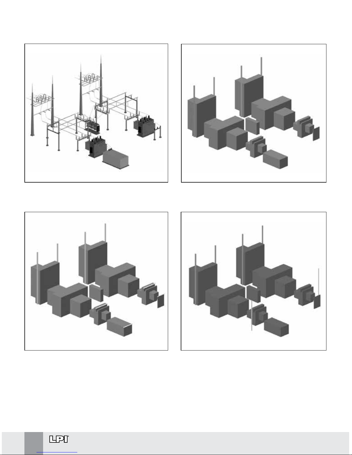
Substation Placement Methodology
Case Study: 69 kV substation in IEEE Std. 998.
Step 1: Simplify the equipment and buses.
Step 2: Perform strike probability analysis
(SPA) utilising a dynamic EGM and published
lightning stroke statistics.
Step 3: Position air terminals in optimum
locations based on the SPA and attractive
radius calculations in accordance with LIT.
www.lpi.com.au
LIGHTNING PROTECTION INTERNATIONAL PTY LTD
5
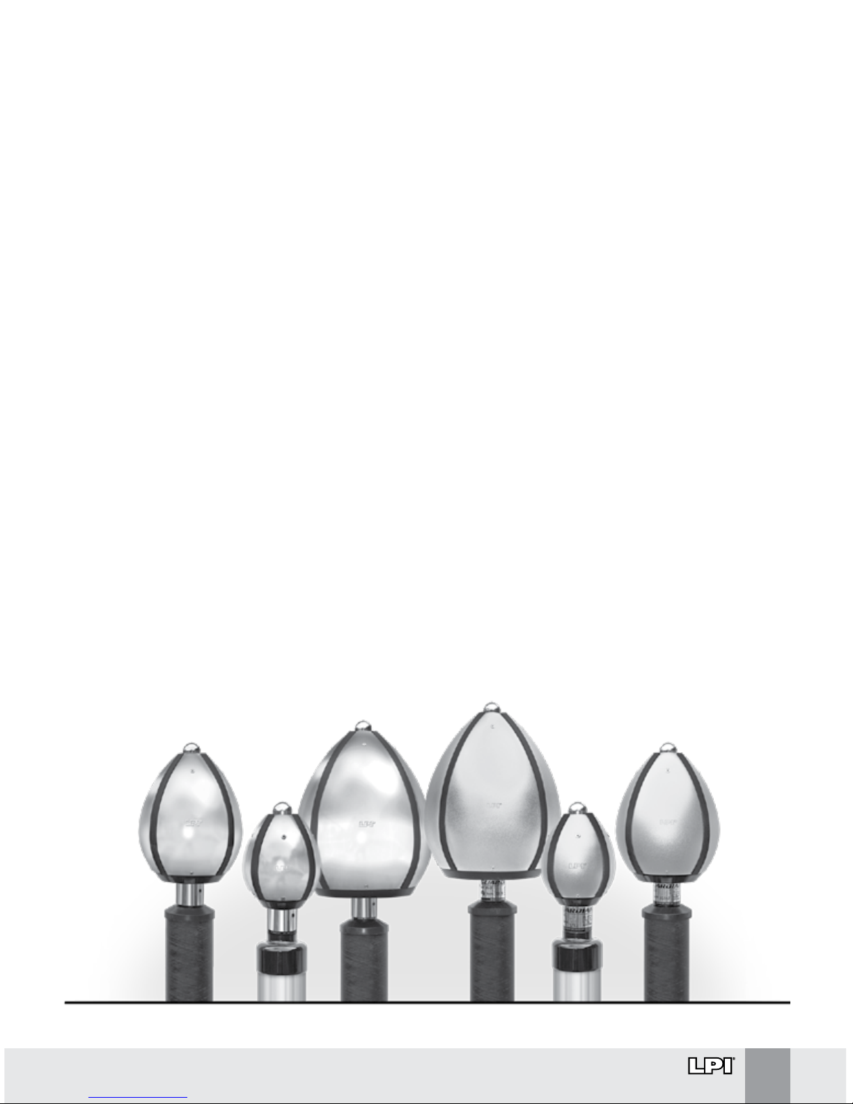
Air Terminal (Hardware)
The new Guardian Plus™ (G+) air terminal range has been developed after taking into account
the latest international research into the effect of space charge and air terminal geometry,
characteristics of long sparks, lightning characteristics and statistics, and the lightning
attachment process itself.
The design of the G+ air terminals was based on detailed modelling and calculations geared
towards achieving optimum corona performance in the quasi-static phase of a thunderstorm.
Some of the key technical factors considered in the optimised design included the:
∆ Dome size (there are three sizes to cater for all practical installation scenarios);
∆ Tip radius of curvature and tip protrusion (optimised to minimise corona discharge);
∆ Materials (robust, long-lasting yet cost-effective options).
Furthermore, under the dynamic phase of lightning, i.e., during the descent of the downward
leader, the response of the air terminal to the rapidly-escalating electric field is achieved via
capacitive coupling to four independent panels on the air terminal, leading to a triggering spark
that changes the spatial electric field as part of the leader initiation process.
Final optimisation of the G+ corona performance and upward leader initiation under dynamic
electric fields was achieved via extensive testing at a state-of-the-art high-voltage test
laboratory, namely the National Engineering Laboratory for Ultra High Voltage Technology
(NELUHVT) located near Kunming in China. The NELUHVT is an outdoor facility and hence the
air terminals were not only tested under different electrical conditions but also a range of
environmental effects.
LIGHTNING PROTECTION INTERNATIONAL PTY LTD
www.lpi.com.au
6
WARRANTY
LPI’s Guardian Plus terminals (including all accessories) are guaranteed against
defects in materials or workmanship for a period of 5 years from the original sales
date when it was purchased from LPI or one of its authorised distributors.
The warranty is limited to the ex-factory cost of replacement of equipment providing
it has been installed and/or certified by LPI or its distributor. All other costs such as
freight, re-installation, loss of profit, or insurance premiums are not included.
Responsibility for other direct or indirect damages or death is also specifically
excluded from the warranty.
DISCLAIMER
The LPI Guardian Plus design software LITCalc provides the end-user with a
customised lightning protection design in compliance with the Leader Inception
Theory included in IEEE Std. 998 and other standards.
LPI has a policy of continuing research and product improvement and hence
retains the right without notice to alter future design methods or specifications
in accordance with revisions of applicable standards or other validated research
programs.
The range of Guardian Plus air terminals or, to our knowledge, any other lightning
protection system cannot provide 100% protection and it is not inferred.
www.lpi.com.au
LIGHTNING PROTECTION INTERNATIONAL PTY LTD
7
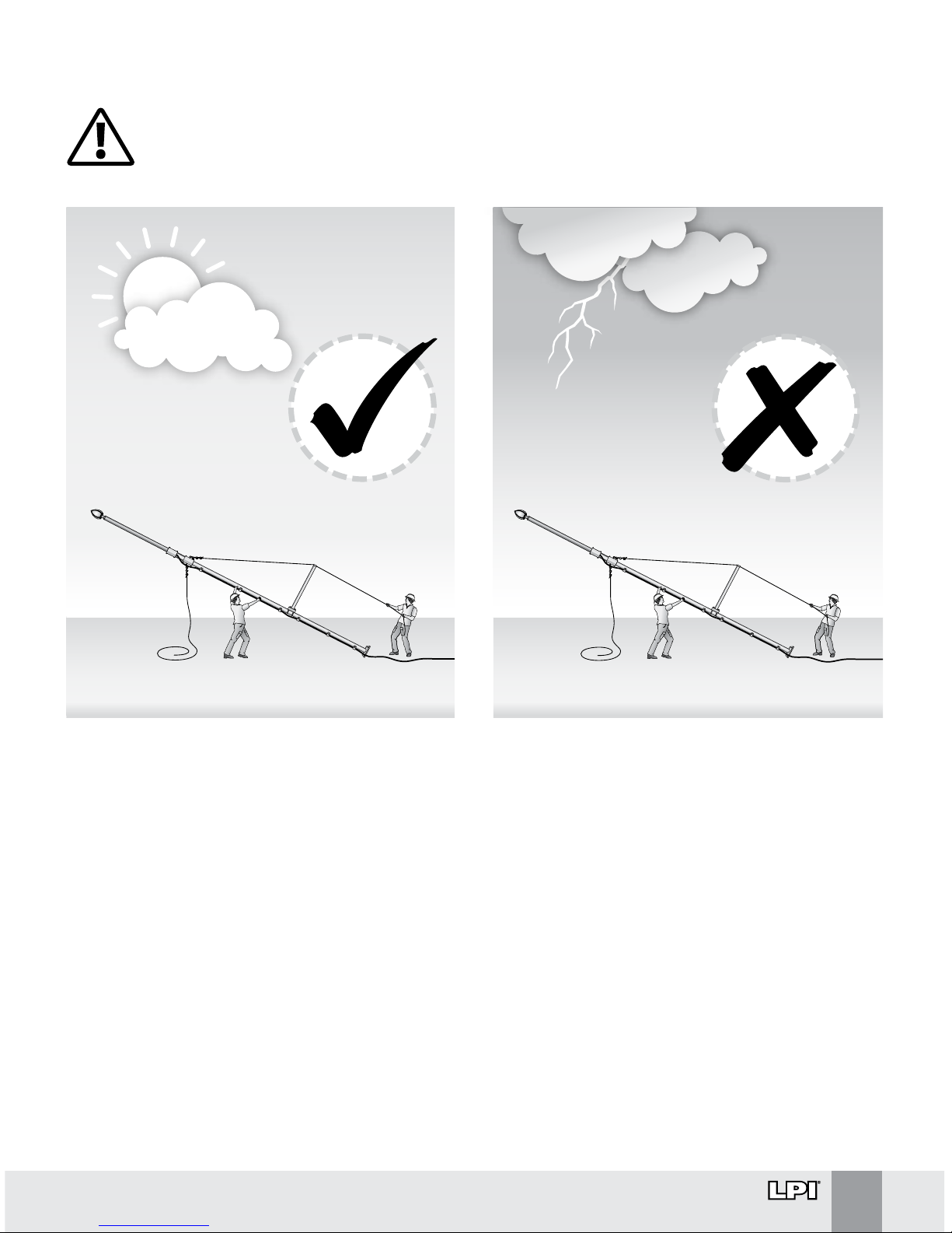
Figure 1.
Safety Guidelines for Installation
The LPI Guardian Plus terminals should only be installed when there is no threat of a
thunderstorm and lightning.
Other Recommendations:
∆ Ensure safe working environments and practices to local codes
∆ Use personal protective equipment during installation
∆ Use mechanical methods of raising and installing masts over 6 m
∆ Cordon off the area below the installation point
∆ Check for overhead powerlines, live conductors and any other obstructions before lifting or
raising
∆ Ensure enough personnel are used to safely conduct all aspects of the installation

LIGHTNING PROTECTION INTERNATIONAL PTY LTD
www.lpi.com.au
8
Checking Lightning Protection Components Supplied
The LPI Guardian Plus components received should be checked against the “bill of materials” for
loss during shipping and for damage.
Check the following:
∆ Air terminals have not been dented or damaged in any way during transit
∆ Instructions, warning labels, warranty, test certificate and relevant mast base
components are supplied
∆ HVSC Plus cable drum (if supplied) is not damaged
∆ Correct HVSC Plus length(s) have been supplied
∆ There is no obvious damage to the HVSC Plus cable
∆ If a factory completed upper termination is supplied, check to see that it is not damaged
and confirm inside or outside termination(s)
∆ Order of lengths and quantities of HVSC Plus (if multiple lengths on one drum), will be
shown on the side of the cable drum(s)
LPI Guardian Plus Installation
All site and safety requirements must be followed during the installation of the LPI Guardian
Plus System. The correct order of installation is as follows:
1. Installation of the lightning earth.
2. Installation of the HVSC Plus downconductor.
3. Preparation of the lower termination of the HVSC Plus downconductor and connection
to the lightning earth.
4. Preparation of the upper termination of the HVSC Plus downconductor and connection
to the Guardian Plus terminal.
5. Preparation and raising of the mast into position.
Notes:
∆ The installation must comply with all of the relevant local standards and regulations
∆ If the Guardian Plus terminal needs to be raised prior to connection to the lightning
earth or immediate connection is not possible, then connect the lower end of the
downconductor to structural steel reinforcing or another suitable earth point
www.lpi.com.au
LIGHTNING PROTECTION INTERNATIONAL PTY LTD
9
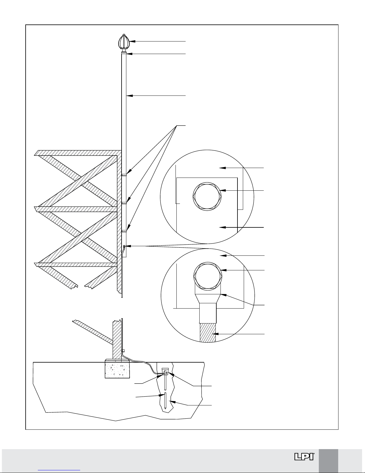
BASE OF MAST
PIPE
MOUNTING BOLT &
STAINLESS STEEL
WASHER
COPPER TAPE
BASE OF MAST PIPE
MOUNTING BOLT &
STAINLESS STEEL
WASHER
COMPRESSION
LUG
COPPER CABLE
LPI SADDLES FOR CANTILEVER MAST
LPI GUARDIAN PLUS GI TERMINAL
THREADED GI ADAPTOR (FEMALE THREAD
2 INCH BSP)
MAST ASSEMBLY WITH GI ADAPTOR
LPI LOWER TERMINATION KIT
LPI EARTHING SYSTEM
LPI EARTH ENHANCING MATERIAL
LPI INSPECTION PIT
®
®
®
®
®
®
IMPORTANT:
One Third of the mast
height must be securely
fixed to the structure.
Guardian Plus Terminal
to be a minimum of 2
metres above the
highest point of the
building or rooftop
objects.
Recommended
clearance height = 5
metres.
Figure 2.
LIGHTNING PROTECTION INTERNATIONAL PTY LTD
www.lpi.com.au
10
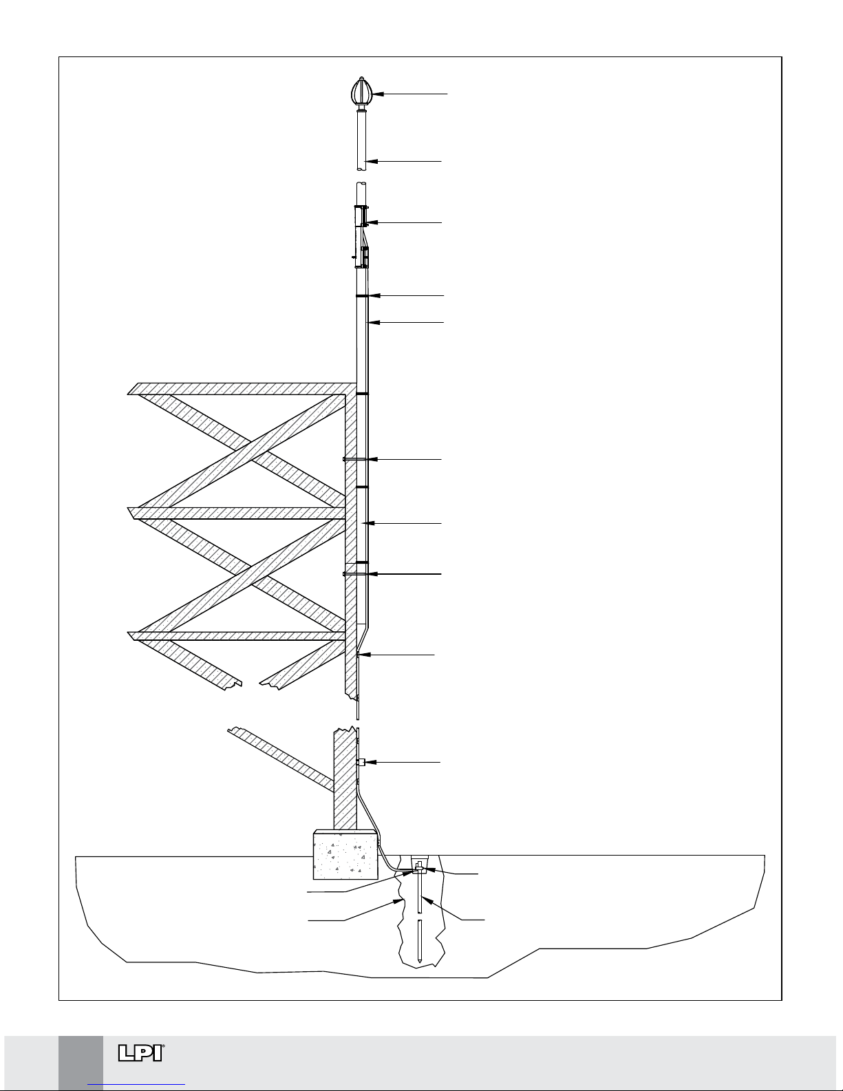
Figure 3.
LPI GUARDIAN PLUS TERMINAL
LPI FRP SUPPORT MAST
LPI INLINE COUPLING
LPI CABLE TIES
LPI HVSC PLUS DOWNCONDUCTOR
LPI U-BOLT
LPI BEAM CLAMP AND CABLE
SUPPORT
LPI LIGHTNING STRIKE RECORDER
LPI LOWER TERMINATION KIT
LPI EARTHING SYSTEM
LPI EARTH ENHANCING
MATERIAL
LPI INSPECTION PIT
LPI LOWER MAST ASSEMBLY
LPI U-BOLT
IMPORTANT:
One Third of the mast
height must be securely
fixed to the structure.
Guardian Plus Terminal
to be a minimum of 2
metres above the
highest point of the
building or attached
objects.
Recommended
clearance height = 5
metres.
®
®
®
®
®
®
®
®
®
®
®
®
®
®
www.lpi.com.au
LIGHTNING PROTECTION INTERNATIONAL PTY LTD
11
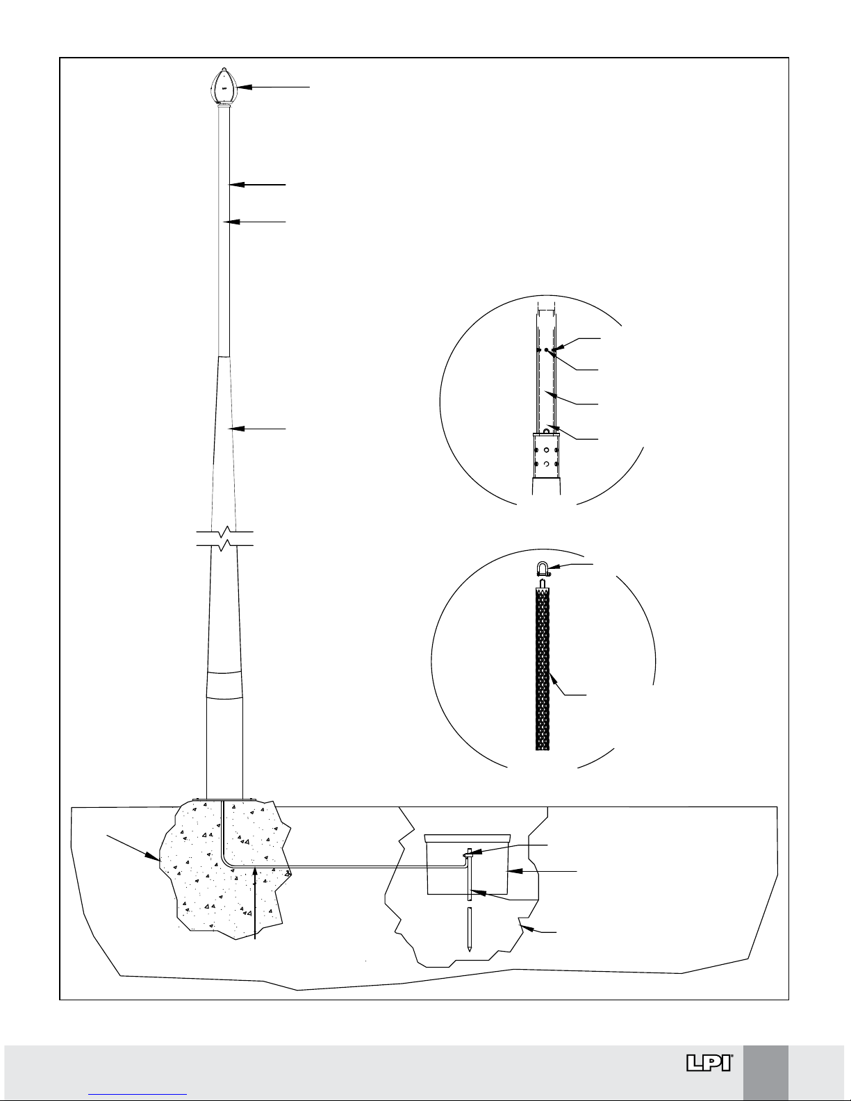
FOOTING
LPI LOWER TERMINATION KIT
LPI EARTHING SYSTEM
®
®
LPI EARTH ENHANCING
MATERIAL
®
LPI INSPECTION PIT
®
TERMINATION OF DOWNCONDUCTOR
TO EARTH
LPI GUARDIAN PLUS TERMINAL
LPI FRP SUPPORT MAST
LPI HVSC PLUS DOWNCONDUCTOR
OR LPI COPPER TAPE
(DOWNCONDUCTOR TO BE
RUN INTERNALLY)
®
®
®
®
FREESTANDING
MAST
CABLE SOCK LOCATED INSIDE
FREESTANDING MAST,
ATTACHED TO WELDED
LUG AT TOP VIA SHACKLE
SHACKLE
INTERNAL SPIGOT 59mm
OD FOR SLIDING FIT
M6 x 10 PAN HEAD SCREWS
3 PLACES AT 120°
CABLE SOCK
DETAIL
SPIGOT
DETAIL
3 HOLES DRILLED ON SITE,
Ø 6.5 SPACED AT 120°
WELDED LUG
Figure 4.
LIGHTNING PROTECTION INTERNATIONAL PTY LTD
www.lpi.com.au
12
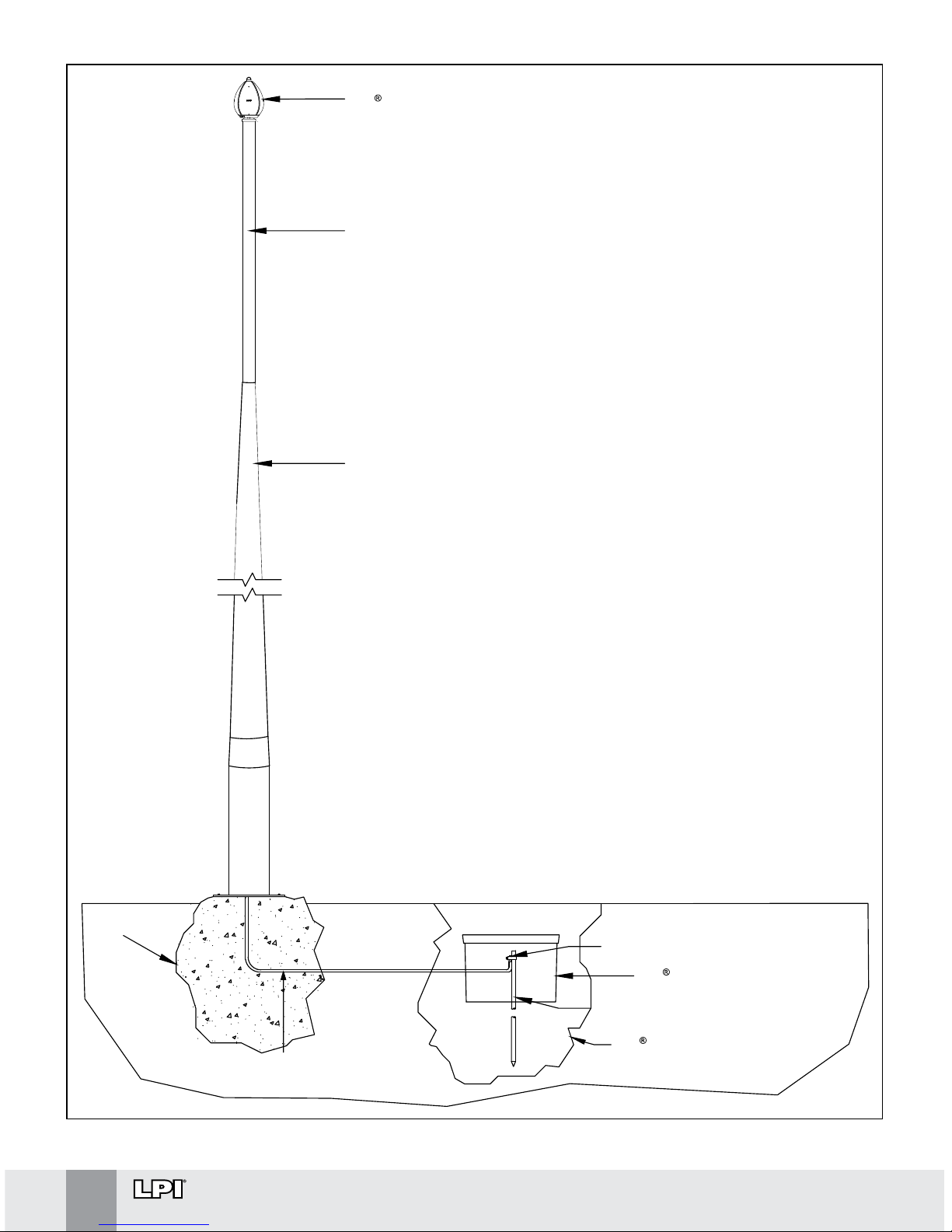
Figure 5.
LPI INSPECTION KIT
LPI GUARDIAN PLUS GI TERMINAL
FOOTING
LPI LOWER TERMINATION KIT
LPI EARTHING SYSTEM
®
®
LPI EARTH ENHANCING
MATERIAL
BONDING OF METALLIC
MAST TO EARTH
MAST CONVEYS LIGHTNING
ENERGY TO EARTH
FREESTANDING
MAST

www.lpi.com.au
LIGHTNING PROTECTION INTERNATIONAL PTY LTD
13
Installation of the Lightning Earth
Before installation of the lightning protection earth, consult site drawings of underground
services so that these are not damaged during installation of the earthing system.
An earth of ≤ 10 W is generally required for the successful operation of LPI Guardian Plus terminal.
For standalone Guardian Plus installations, LPI recommends the installation of a radial lightning
earth, as shown in Figure 6.
∆ The minimum earthing system comprises 3 x 10 metre radials, typically utilising 25 x 3 mm
copper tape
∆ Each radial must be installed in a trench with approximate dimensions 500 mm (depth) x
200 mm (width)
∆ An earth rod should be driven at the end of each radial. The depth of the earth rod length
should be tailored to the soil resistivity profile of the installation location
∆ The earth rod material should also be matched with the local conditions, i.e., typically
copper-bonded steel, but stainless steel may be required in more aggressive soils
∆ The use of earth rod clamps to fix the tape to rods is recommended
Note: If space constraints do not permit the installation of a radial earth system per above,
consult with LPI or an authorised distributor for further advice.
If the Guardian Plus is installed within an earth grid, e.g., in a substation, then the earth grid can
substitute the radials. However, an earth rod of suitable depth must be installed at the base of
the mast supporting the Guardian Plus air terminal.
Some of the practical aspects of the lightning earth installation are as follows:
∆ Waterproofing mastic tape should be used on all mechanical connections
∆ The use of earth enhancing compounds is recommended around all earth electrodes
installed, e.g., LPI RESLO, LPI SRIM or LPI GRIP, especially in areas where soil resistivity is
moderate to high
∆ An earth pit should be installed where the end of the downconductor terminates to the
lightning earth (see Figure 6). The earth pit provides an access point for disconnection and
future testing of the earthing system
∆ When installing the earth rods, use driving heads to prevent mushrooming of the top of the
rod and when using coupled rods. Use a post or picket driver
Note: do not connect the lower termination of the downconductor to the earthing system at
this point in time.
 Loading...