

Page 1

S2.200
S2.250
S2.300
S2.500
Page 2

Introduction
InnoVAte or DisintegrAte!
Thank you for purchasing the Lighting Audio Strike Amplifier.
Our customers have come to expect that Lightning Audio pushes the edge in audio. Now we will push the edge in the
amplifier and woofer business with high value and high performance models.
For the first time, amplifiers can be personalized by the customer with accessories like the POWERCell and FANModule.
These accessory components are designed with performance and customization in mind.
If, after reading your manual, you still have questions regarding this product, we recommend that you see your Lightning
Audio dealer. If you need further assistance, you can call us direct at 1-800-669-9899. Be sure to have your serial num-
ber, model number and date of purchase available when you call.
The serial number can be found on the outside of the box. Please record it in the space provided below as your perma-
nent record. This will serve as verification of your factory warranty and may become useful in recovering your amplifier if
it is ever stolen.
Serial Number: ______________________________________
Model Number: ______________________________________
Improper wiring connections can seriously damage
the Amplifier and your vehicle. Be sure to carefully
follow the connection instructions in this manual.
Note: If you are unsure of the connections, contact
your dealer.
Page 3

- 1 -
Strike S2.300
Strike S2.500
• Power RAting: 90w x 2 @ 4 ohms
170w x 2 @ 2ohms (less than 1% THD)
340w x 1 @ 4ohms
• Input SensitiVity: 150mV minimum
• High LeVel Input: 1V - 8V
• SignAl to Noise rAtio: Greater than 90dB
• ChAnnel SepArAtion: Greater than 55dB
• CrossoVer: 60-400Hz Variable, High/Low/ All Pass switch
• CrossoVer Slope: 12 dB/Octave
• EquAlizAtion: Remote Juice Boost,
Variable +12dB @ 50Hz (Remote included)
• amplifier Fuse VAlue: (2) 20A
• chAssis size: 10.25”W x 2.25”H x 10.0”L*
• Power RAting: 150w x 2 @ 4ohms
250w x 2 @ 2ohms (less than 1% THD)
500w x 1 @ 4ohms
• Input SensitiVity: 150mV minimum
• High LeVel Input: 1V - 8V
• SignAl to Noise rAtio: Greater than 90dB
• ChAnnel SepArAtion: Greater than 55dB
• CrossoVer: 60-400Hz Variable, High/Low/All Pass switch
• CrossoVer Slope: 12 dB/Octave
• EquAlizAtion: Remote Juice Boost
Variable +12dB @ 50Hz (Remote included)
• amplifier Fuse VAlue: (3) 20A
• chAssis size: 10.25”W x 2.25”H x 17.0”L*
SpecificAtions
• Power RAting:60w x 2 @ 4ohms
100w x 2 @ 2ohms (less than 1% THD)
200w x 1 @ 4ohms
• Input SensitiVity:150mV minimum
• High LeVel Input: 1V - 8V
• SignAl to Noise rAtio: Greater than 90dB
• ChAnnel SepArAtion: Greater than 55dB
• CrossoVer: 80Hz High/Low/All Pass switch
• CrossoVer Slope: 12dB/Octave
• EquAlizAtion: –
• amplifier Fuse VAlue: (1) 25A
• chAssis size: 10.25”W x 2.25”H x 8.5”L*
Specifications subject to change without notice
StriKe S2.200
Strike S2.250
• Power RAting: 75w x 2 @ 4ohms
115w x 2 @ 2ohms (less than 1% THD)
230w x 1 @ 4ohms
• Input SensitiVity: 150mV minimum
• High LeVel Input: 1V - 8V
• SignAl to Noise rAtio: Greater than 90dB
• ChAnnel SepArAtion: Greater than 55dB
• CrossoVer: 60-400Hz Variable, High/Low/All Pass switch
• CrossoVer Slope: 12dB/Octave
• EquAlizAtion: Juice Boost +6dB @ 50Hz (on/off switch)
• amplifier Fuse VAlue: (1) 30A
• chAssis size: 10.25”W x 2.25”H x 8.5”L*
2-ChAnnel Amplifiers
*End Cap adds 2.4” to Chassis length
Page 4
- 2 -
Specifications subject to change without notice
Accessories
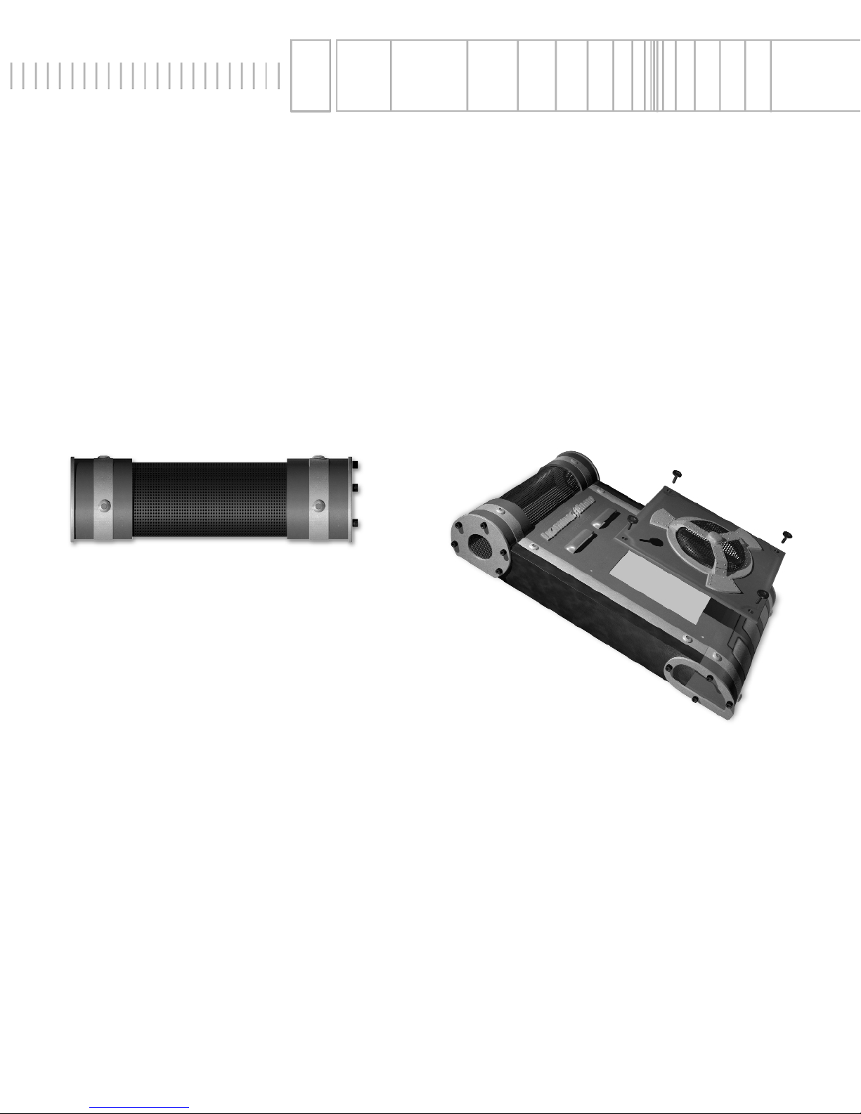
POWERCell: All 6 amplifiers can benefit from the
addition of the POWERCell, an electrolytic capacitor
module that integrates directly to the amplifier through a
docking station. The POWERCell delivers big power for
transients faster than the vehicle’s electrical system. The
POWERCell enables the Lightning Audio amplifiers to
withstand the rigors of driving 2 ohm loads.
FANModule: Keeping powerful amplifiers cool,
especially into lower impedance, is the key function of the
FANModule. Easily integrated into the top of the amplifier,
the FANModule provides constant cooling over the entire
PC board and output devices improving sound quality by
reducing distortions caused by thermal gradients.
Page 5
- 3 -
Strike S2.250
Design FeAtures
Strike S2.200
A
A
B
C
F
G
B
C
D
H
I
J
D
E
E
F
G
H
Page 6
- 4 -
Design FeAtures
Strike S2.300
Strike S2.500
L
L
B
A
C
F
G
B
A
C
I
M
K
D
H
I
M
K
D
E
E
F
G
H
Page 7

- 5 -
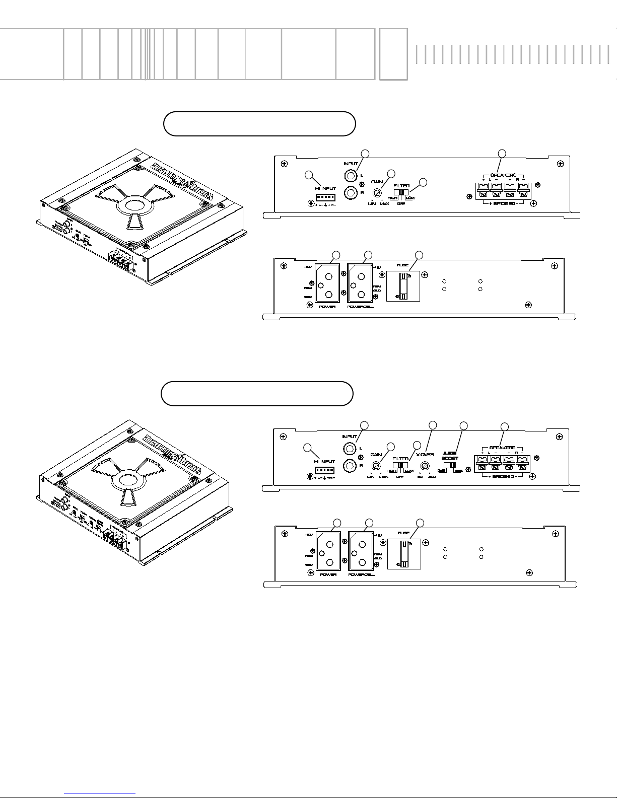
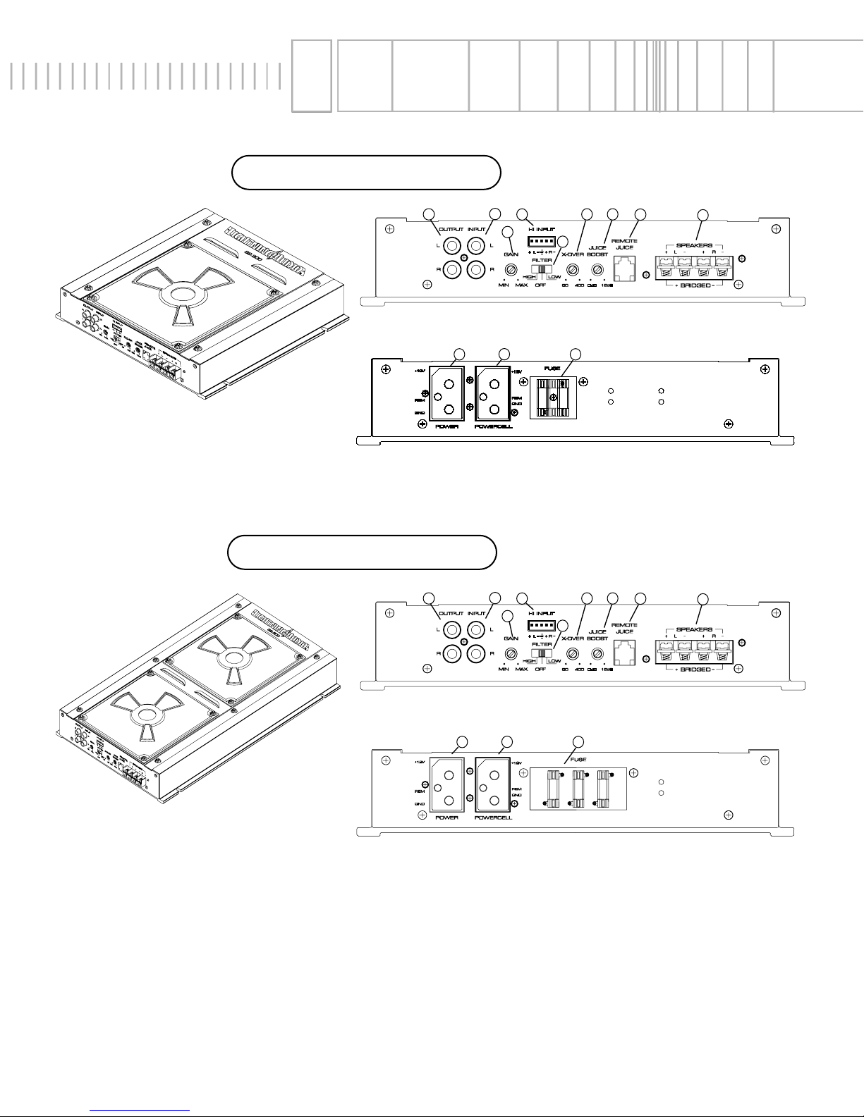
A. High Level (Speaker) Inputs : The high level inputs use a detachable connector terminated with 20 AWG leads.
These inputs should be used if the source unit has only speaker line (high level) outputs and not RCA outputs.
B. RCA Input Jacks – Line Level from Radio Pre-outs: The industry standard RCA jack provides an easy connection
for signal level input. They are gold-plated to resist the signal degradation caused by corrosion.
C. Gain Control: The input gain control is preset to match the output of most source units. They can be adjusted to
match output levels from a variety of source units.
D. Crossover Filter Switch: High for High Pass - Mid-Tweeter.
Off for All Pass - Full Range.
Low for Low Pass - Subs.
E. Speaker Connections: Follow correct polarity, and do not Ground any speaker wires. Do not connect any speaker
wires together.
F. Power Connector Plug: Connects Power, Ground, and Remote
G. Power Cell (Capacitor) Plug: Power Cell has 2 active leads for B+ and Ground
H. Power Fuse: If this Fuse should blow, determine the cause or see your authorized dealer. Never replace the fuse
with one of greater value than the original
I. Adjustable Crossover Frequency Control: 60-400Hz.
J. Juice Boost Switch: Applies 6dB of 50Hz Bass Boost.
K Juice Boost Remote Module: The Juice Boost remote module has a Green “Operation” indicator and Red
“Protection” indicator. The Remote Juice Boost Module allows adjustment of the overall gain or volume of the
amplifier. It operates only when the crossover switch is in Low Pass position. It does not alter the frequency
response, but instead allows control of the overall gain of the amplifier driving your woofers. Most experienced
users adjust the Juice Boost knob on the amp for the maximum desired amount of bass boost, and then plug
in the module to control how much of that boost they want to unleash to their subwoofers.
L. Pass Thru Outputs: The Pass-Thru provides a convenient source for daisy-chaining an additional amplifier without
running and extra set of RCA cables from the front of the vehicle to the rear amplifier location.
M. Juice Boost: Applies 0-12dB of 50Hz Bass Boost.
Design FeAtures
ChecK our website www.LightningAudio.com
for updAtes on your products.
Page 8

- 6 -
InstAllAtion ConsiderAtions
The following is a list of tools you will need for installing the Lightning Audio
Adequate Length Voltmeter
Wire strippers Battery post wrench
Electric hand drill w/assorted bits Wire cutters
Adequate Length—Red Power Wire Assorted connectors
Adequate Length—Remote Turn-on Wire Wire crimpers
Adequate Length—Black Grounding Wire
This section focuses on some of the vehicle considerations for installing your new Lightning Audio amplifier. Checking
your battery and present sound system, as well as pre-planning your system layout and best wiring routes will save
installation time. When deciding how to lay out your new system, be sure that each component will be easily accessible
for making adjustments.
Before beginning any installation, be sure to follow these simple rules:
1. Be sure to carefully read and understand the instructions before attempting to install the amplifier.
2.
For safety, disconnect the negative lead from the battery prior to beginning the installation.
3. For easier assembly, we suggest you run all wires prior to mounting your amplifier in place.
4. Route all of the RCA cables close together and away from any high current wires.
5. Use high quality connectors for a reliable installation and to minimize signal or power loss.
6.
Think before you drill! Be careful not to cut or drill into gas tanks, fuel lines, brake or hydraulic lines, vacuum lines
or electrical wiring when working on any vehicle.
7. Never run wires underneath the vehicle. Running the wires inside the vehicle provides the best protection.
8. Avoid running wires over or through sharp edges. Use rubber or plastic grommets to protect any wires routed
through metal, especially the firewall.
9.
ALWAYS protect the battery and electrical system from damage with proper fusing. Install a fuseholder and appropriate fuse on the +12V power wire within 18” (45.7 cm) of the battery terminal.
10. When grounding to the chassis of the vehicle, scrape all paint from the metal to ensure a good, clean ground connection. Grounding connections should be as short as possible and always be connected to metal that is welded to
the main body, or chassis, of the vehicle.
Page 9

- 7 -
Mounting LocAtion
The mounting location and position of your amplifier will have a great effect on its ability to dissipate the heat generated
during normal operation To maximize the performance of your amplifier, care should be taken to ensure adequate ventilation.
Trunk Mounting
Mount the amplifier vertically this will provide the best cooling of the amplifier.
Mounting the amplifier on the floor of the trunk will work but provides less cooling capability than vertical mounting.
Mounting the amplifier upside down to the rear deck of the trunk will not provide proper cooling and will severely affect
the performance of the amplifier and is strongly not recommended.
Passenger Compartment Mounting
Mounting the amplifier in the passenger compartment will work as long as you provide a sufficient amount of air for the
amplifier to cool itself. If you are going to mount the amplifier under the seat of the vehicle, you must have at least 1"
(2.54cm) of air gap around the amplifier's heatsink.
Mounting the amplifier with less than 1" (2.54cm) of air gap around the amplifier's heatsink in the passenger compartment will not provide proper cooling and will severely affect the performance of the amplifier and is strongly not recom-
mended.
Engine Compartment Mounting
Lightning Audio amplifiers should never be mounted in the engine compartment. Not only will this void your warranty but
could create an embarrassing situation caused by the ridicule from your friends.
Page 10

- 8 -
BAttery And ChArging
Amplifiers will put an increased load on the vehicle's battery and charging system. We recommend checking your
alternator and battery condition to ensure that the electrical system has enough capacity to handle the increased load of
your stereo system. Stock electrical systems which are in good condition should be able to handle the extra load of any
Lightning Audio amplifier without problems, although battery and alternator life can be reduced slightly. To maximize the
performance of your Lightning Audio amplifier, we suggest the use of a heavy duty battery and an energy storage
capacitor.
CAUTION: Avoid running power wires near the low level input cables, antenna, power leads, sensitive equipment or harnesses. The power wires carry substantial current and could induce noise into the audio system.
• For safety, disconnect the negative lead from the battery prior to beginning the installation.
1. Plan the wire routing. Take care when running signal level RCA cables to keep them close together but isolated from
the amplifier's power cables and any high power auto accessories, especially electric motors. This is done to prevent
coupling the noise from radiated electrical fields into the audio signal. When feeding the wires through the firewall or
any metal barrier, protect them with plastic or rubber grommets to prevent short circuits. Leave the wires long at this
point to adjust for a precise fit at a later time.
2. Prepare the
Power cable for attachment to the amplifier by stripping 1/2" of insulation from the end of the wire. Insert
the bared wire into the B+ terminal and tighten the set screw to secure the cable in place.
NOTE: The B+ cable MUST be fused 18" or less from the vehicle's battery. Install the fuseholder under the
hood and prepare the cable ends as stated above. Connections should be water tight.
Trim the power cable within 18" of the battery and strip 1/2" of insulation from the end of the wire. Cut the wire loop
that is attached to the fuseholder in half and splice the fuse into the power line using appropriate inline connectors. Use the section of cable that was trimmed earlier and connect it to the other end of the fuseholder.
3. Strip 1/2" from the battery end of the power cable and crimp a large ring terminal to the cable. Use the ring terminal
to connect to the battery positive terminal. Do not install the fuse at this time.
4. Prepare the Ground cable for attachment to the amplifier by stripping 1/2" of insulation from the end of the wire.
Insert the bared wire into the GND terminal and tighten the set screw to secure the cable in place. Prepare the chassis ground by scraping any paint from the metal surface and thoroughly clean the area of all dirt and grease. Strip the
other end of the wire and attach a ring connector. Fasten the cable to the chassis using a non-anodized screw and a
star washer.
5. Prepare the REM turn-on wire for connection to the amplifier by stripping 1/2" of insulation from the wire end. Insert
the bared wire into the REM terminal and tighten the set screw to secure the cable into place. Connect the other end
of the REM wire to a switched 12 volt positive source. The switched voltage is usually taken from the source unit's
auto antenna or the accessory lead. If the source unit does not have these outputs available, the recommended
solution is to wire a mechanical switch in line with a 12 volt source to activate the amplifier.
6. Securely mount the amplifier to the vehicle or amp rack. Be careful not to mount the amplifier on cardboard or plastic panels. Doing so may enable the screws to pull out from the panel due to road vibration or sudden vehicle stops.
7. Connect the source signal to the amplifier by plugging the RCA cables/high level inputs into the input jacks at the
amplifier.
8. Connect the speakers. Strip the speaker wires 1/2" and insert into the speaker terminal and tighten the set screw to
secure into place. Be sure to maintain proper speaker polarity. DO NOT chassis ground any of the speaker
leads as unstable operation may result.
9. Perform a final check of the completed system wiring to ensure that all connections are accurate. Check all power
and ground connections for frayed wires and loose connections which could cause problems.
Wiring the System
Page 11
- 9 -
Using PAssiVe CrossoVers
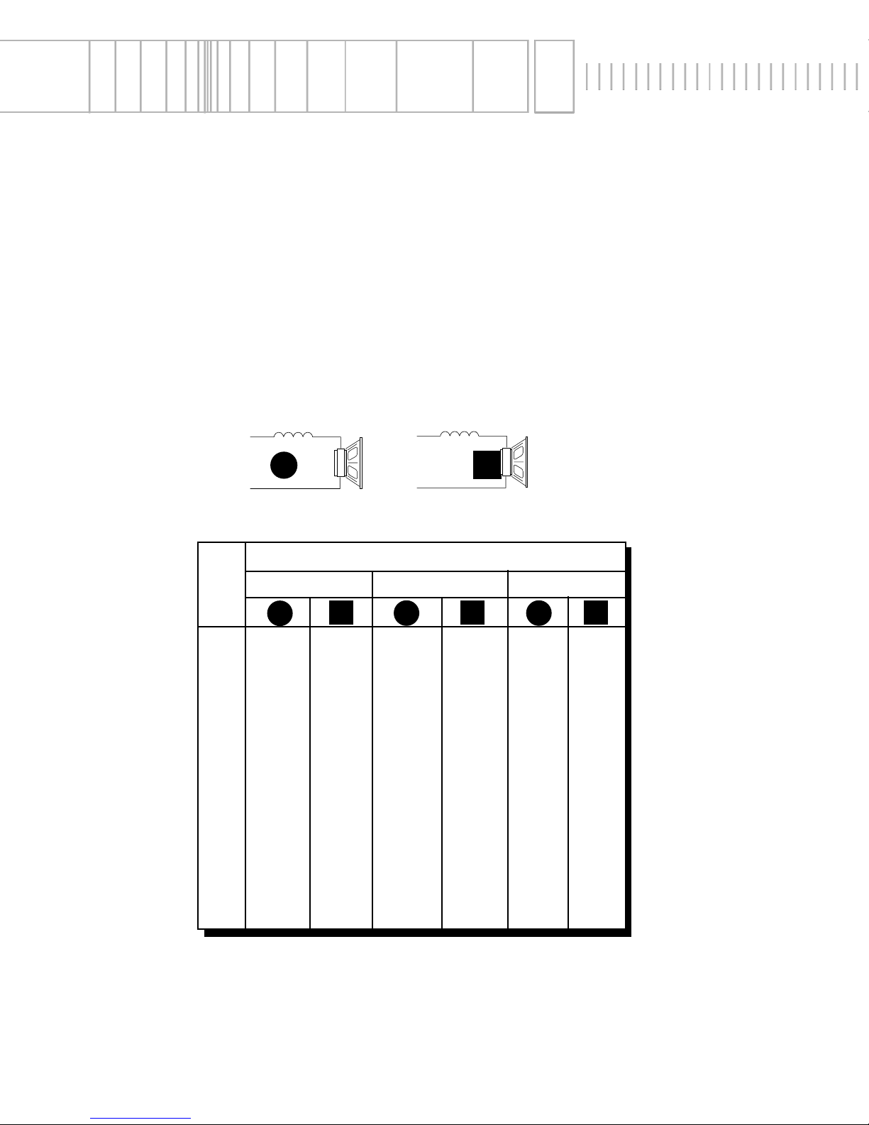
A passive crossover is a circuit that uses capacitors and/or coils and is placed on speaker leads between the amplifier
and speaker. The crossover delegates a specific range of frequencies to the speaker for optimum driver performance. A
crossover network can perform one of three functions: High-Pass (capacitors), Low-Pass (inductors or coils) and
Bandpass (combination of capacitor and coil).
The most commonly used passive crossover networks are 6dB/octave systems. These are easy to construct and require
one component per filter. Placing this filter in series with the circuit will reduce power to the speaker by 6dB/octave
above or below the crossover point depending on whether it is a high-pass or low-pass filter. More complex systems
such as 12dB/octave or 18dB/octave can cause impedance problems if not professionally designed.
Passive crossovers are directly dependent upon the speaker's impedance and component value for accuracy. When
passive crossover components are used in multiple speaker systems, the crossover's effect on the overall impedance
should be taken into consideration along with the speaker's impedance when determining amplifier loads. CAUTION:
The Lightning Audio amplifiers are not recommended for impedance loads below 2Ω stereo and 4Ω bridged
(mono) loads.
6dB/Octave Low-Pass
6dB/Octave High-Pass
Freq.
Hertz
Speaker Impedance
80 4.1mH 1000µF 8.2mH 500µF 16mH 250µF
100 3.1mH 800
µF 6.2mH 400µF 12mH 200µF
130 2.4mH 600
µF 4.7mH 300µF 10mH 150µF
200 1.6mH 400
µF 3.3mH 200µF 6.8mH 100µF
260 1.2mH 300
µF 2.4mH 150µF 4.7mH 75µF
400 .8mH 200
µF 1.6mH 100µF 3.3mH 50µF
600 .5mH 136
µF 1.0mH 68µF 2.0mH 33µF
800 .41mH 100
µF .82mH 50µF 1.6mH 26µF
1000 .31mH 78
µF .62mH 39µF 1.2mH 20µF
1200 .25mH 66µF .51mH 33µF 1.0mH 16µF
1800 .16mH 44
µF .33mH 22µF .68mH 10µF
4000 .08mH 20
µF .16mH 10µF .33mH 5µF
6000 51
µH14µF .10mH 6.8µF .20mH 3.3µF
9000 34µH 9.5µF68µH 4.7µF .15mH 2.2µF
12000 25
µH 6.6µF51µH 3.3µF 100µH 1.6µF
2 OHMS
8 OHMS
4 OHMS
L
C L
C
L C
L
C
L = Low-Pass (Inductor)
C = High-Pass (Capacitor)
For more information, see your Authorized Lightning Audio Dealer.
Page 12

- 10 -
InstAllation
• For safety, disconnect the negative lead from the car battery prior to beginning the installation
Trunk Mounting
Mounting the amplifier vertically on a surface will provide the best cooling for the amplifier.
Passenger Compartment Mounting
Mounting the amplifier in the passenger compartment will work as long as you provide a sufficient amount of air for the
amplifier to cool itself. If you are going to mount the amplifier under the seat of the vehicle, you must have at least 1”
(2.54cm) of air gap around the amplifier’s heatsink.
B+ Terminal
The B+ cable MUST be fused 18” (45cm) or less from the vehicle’s battery. Prepare the cable ends and install the fuse-
holder under the hood. Connections should be water tight.
GND Terminal
Prepare a length of cable to be used for the ground connection. Prepare the chassis ground by scraping any paint from
the metal surface and thoroughly clean the area of all dirt and grease. Fasten the cable to the chassis using a screw.
REM Terminal
Connect the REM wire to a switched 12 volt positive source. The switched signal is usually taken from the source unit’s
auto antenna or the accessory lead. If the source unit does not have these outputs available, the recommended solution
is to wire a mechanical switch in-line with a 12 volt source to activate the amplifier.
Input Connectors
Follow the diagram and connect the appropriate signal cables to the input terminals of the amplifier. Be sure that the
signal cables are routed close together and away from any high current wires.
Speaker Output Terminals
Connect the speaker system to the amplifier by inserting the wires into the corresponding output terminals and tighten
the set screws. Follow the diagram for proper signal polarity. DO NOT chassis ground any of the speaker
wires as unstable amplifier operation may result. CAUTION: This amplifier is not recommended
for impedance loads below 2W stereo and/or 4W bridged (mono).
Gain Control(s)
The amplifier is factory set for optimum dynamic range. The system levels may be adjusted by ear when using a source
unit with higher or lower output levels by using the following procedure.
1. Turn the gain control to minimum (counterclockwise)
2. Play a music track with high dynamic content and turn up the source unit to at least 3/4 volume
3. Slowly increase the gain and set it just below audible distortion or until reaching a comfortable hearing threshold
(whichever occurs first)
Symptom Diagnosis Remedy
Troubleshooting
Amplifier does not turn
on.
B+ or REM not between 10.5 and 15.5
volts or no voltage present
Amplifier is not properly grounded.
Voltage spike from source unit is entering amplifier’s input
Noise is radiating into signal cables
Check the alternator, battery, fuse, and
wiring and repair as necessary
Check wiring and repair as necessary
Connect turn-on module to REM terminal
if pops are eliminated with no input signal to amplifier
Re-route signal cables away from sources of high current
Amplifier Noise
(Turn-On Pop)
Engine Noise
Page 13
- 11 -
+–
4Ω min.
–
+
–
+
2Ω min. 2Ω min.
InstAllAtion
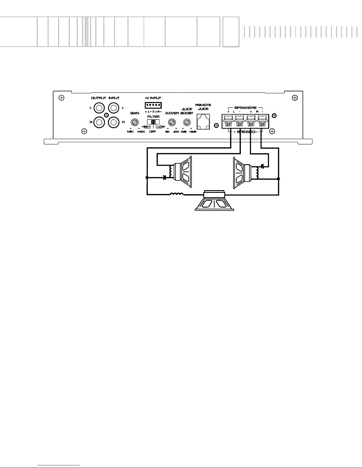
Stereo/Mono OperAtion
• RCA inputs are connected to both left and right channels.
• Gain for left and right channels are set equally to balance the subwoofer.
• Impedance for each channel should be 2Ω minimum.
• Impedance for mono channel should be 4Ω minimum.
• Crossover
is set for Full Range.
• Passive Crossovers are needed for proper stereo/mono operation.
.
Page 14
- 12 -
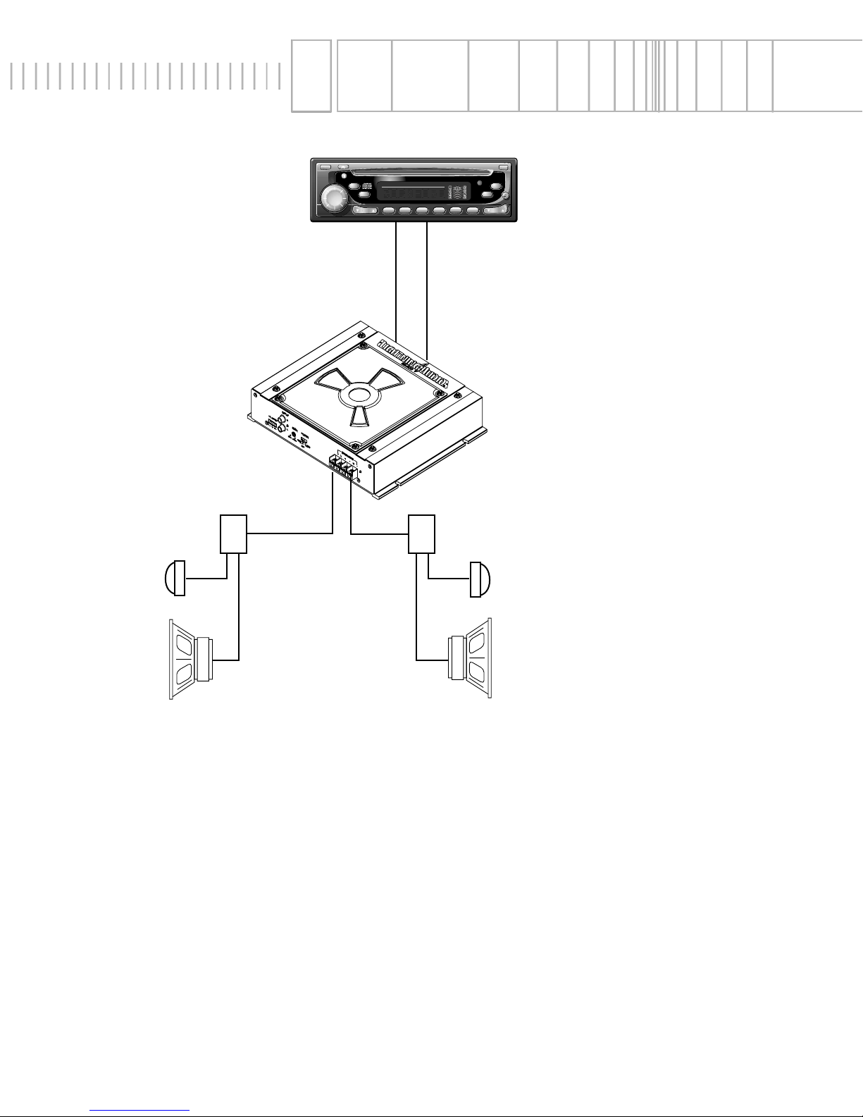
System DiAgrAms
Crossover
Tweeter
Midrange
Crossover
Tweeter
Midrange
BAND
DISP AS/PS
LOUDMODE
MUTE
TUNE
123456
SEL
VOL
COMPACT DISC PLAYER WITH DIGITAL TUNER
RPT
TRACK
SCAN
RDM DISC
PUSH
SEEK
MENU
ST RPT RDMLOUDLOCAL
CD CHANGER CONTROL
2 - WAy System
Page 15
- 13 -
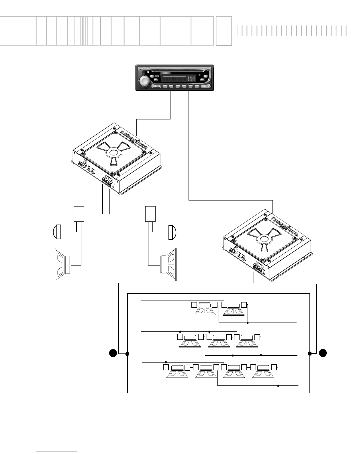
System DiAgrAms
3 - WAy System
Using Single Voice
Coil Woofers
Crossover
Tweeter
Midrange
Crossover
Tweeter
Midrange
+
–
+
+
+
–
–
–
+
+
–
+ +
+
–
+
–
+
–
–
+
– –
+
–
–
8Ω 8Ω
8Ω 8Ω8Ω
4Ω 4Ω 4Ω4Ω
BAND
DISP AS/PS
LOUDMODE
MUTE
TUNE
123456
SEL
VOL
COMPACT DISC PLAYER WITH DIGITAL TUNER
RPT
TRACK
SCAN
RDM DISC
PUSH
SEEK
MENU
ST RPT RDMLOUDLOCAL
CD CHANGER CONTROL
Page 16
- 14 -
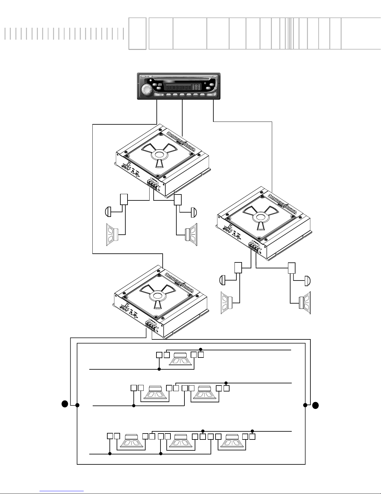
System DiAgrAms
3 - Way System
Using duAl Voice
Coil Woofers
Front
Rear
Crossover
Tweeter
Midrange
Crossover
Tweeter
Midrange
+
+
+
–
–
–
+
–
–
+
–
+
–
+
+
– + –
–
–
+
–
+
+
– + –
–
+
–
+
+
4Ω x 2
4Ω x 2 4Ω x 2
4Ω x 2 4Ω x 2
4Ω x 2
Sub
Crossover
Tweeter
Midrange
Crossover
Tweeter
Midrange
BAND
DISP AS/PS
LOUDMODE
MUTE
TUNE
123456
SEL
VOL
COMPACT DISC PLAYER WITH DIGITAL TUNER
RPT
TRACK
SCAN
RDM DISC
PUSH
SEEK
MENU
ST RPT RDMLOUDLOCAL
CD CHANGER CONTROL
Page 17

- 15 -
InternAtional
InformAtion
Page 18
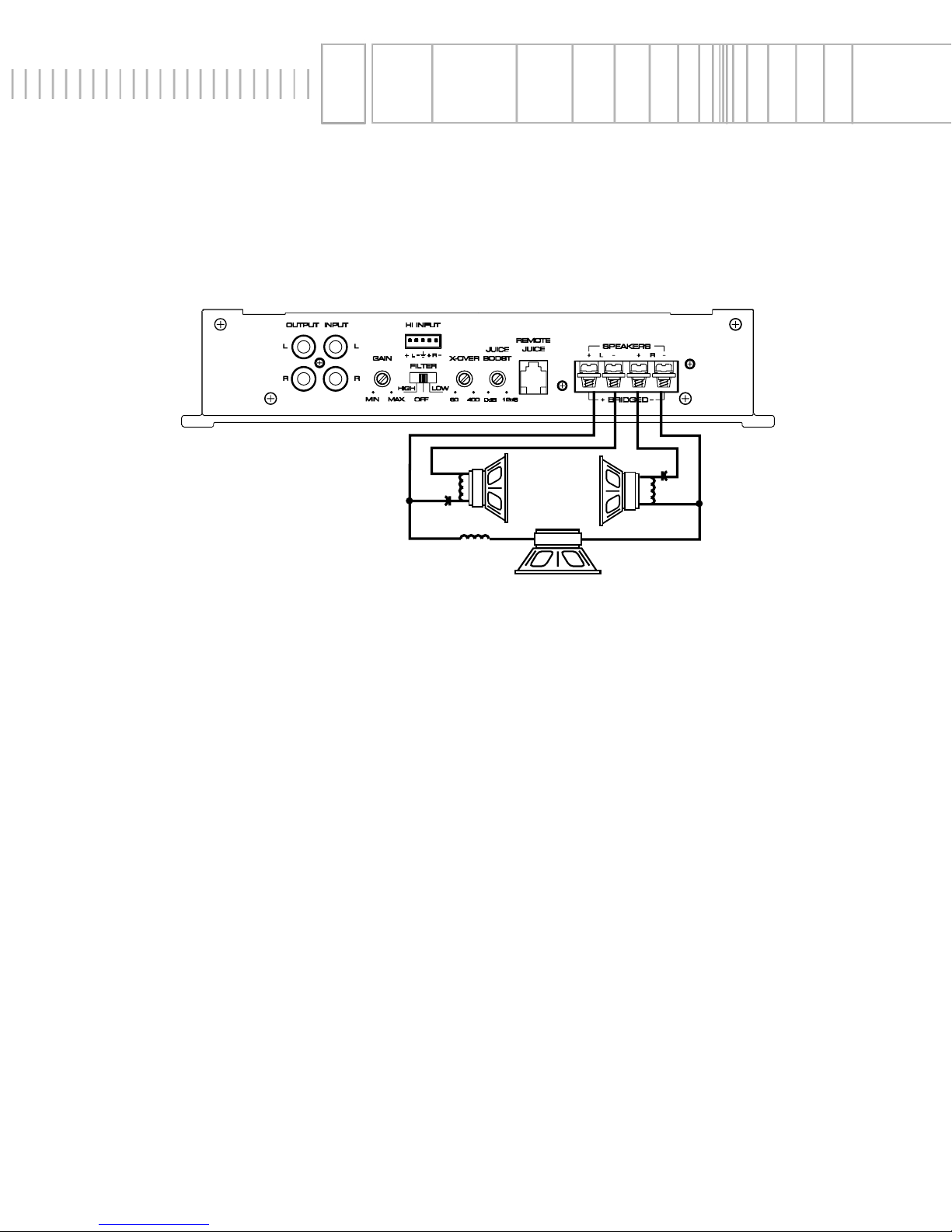
- 16 -
Páginas de Referencia para la Instalación
Amplificadore de Lightning Audio a 2 canale –
Español
InstAllAtion
• Las entradas RCA se conectan a ambos canales izquierdo y derecho
• Las ganancias izquierda y derecha han de ajustarse igual para ambos canales
• La impedancia minima para cada canal debe ser 2Ω.
• La impedancia minima mono debe ser 4Ω.
• Crossover en Full Range
• Crossovers pasivos se requieren para operar el amplificador en estereo/mono
FuncionAmiento
Estereo/Mono
–
2Ω min. 2Ω min.
+
+ –
4Ω min.
+
–
Page 19

- 17 -
INSTALACÍON
• Por seguridad, desconecte el terminal negativo de la bateria antes de comenzar la instalacíon.
Montaje en el Malatero del vehícule
Monte el amplificador verticalmente con las orientadas de arriba hacia abajo. De esta manera conseguirá la mejor
ventilación.
Montaje en el Compartimento de Pasajeros
El montaje en el compartimento de pasajeros sera eficiente en funcion de la ventilación que tenga el amplificador. Si va
a instalar el amplificador bajo un asiento deberá dejar al menos 2.5cm libres sobre la carcasa del amplificador.
Terminal B+
El cable B+ debe ir provisto de un fusible a una distancia no mayor de 45cm de la batería. Prepare el cable e instale el
portafusibles en el compartimento del motor. Las conexiones han de ser impermeables.
Terminal GND
Prepare un trozo de cable para usarlo como toma de masa. Prepare un punto de masa en el chasis rascando y eliminando la pintura de la superfcicie de metal y límpielo de toda suciedad asegure el cable al chasis con un tornillo.
Terminal REM (Encendido remoto)
Conecte el cable REM a un punto de +12V conmutable. La señal se suele coger de la salida auto antena del radio
cassette si este no tiene salida remote.
Conectores de Entrada
Siga el diagrama y conecte los cables adecuados para señal a los terminales de entrada del amplificador. Asegúre se
que los cables de señal esten canalizados en conjunto y lo más lejo posible de cualquier cable de alto amperaje.
Terminales de salida para los Parlantes
Conecte el sistema de parlantes al amplificador insertando los cables correspondientes en los ternminales de salida y
luego aprete los tornillos. Siga el diagrama para una adecuada polaridad de señal.
NO CONECTE ninguno de los
cables de los parlantes a la masa de la carcasa, ya que esto puede resultar en una operación
inestable del amplificador. PRECAUCION: este amplificador no está recomendado para cargas de
impedancia por abajo de 2 Ohmios en estéreo y/ó 4 Ohmios en modo puente (bridge mono).
Control(es) de Ganancia
El amplificador está dispuesto desde la fábrica para óptimo rango dinámico. Los niveles del sistema pueden ser ajustado por oído cuando se utilice una unidad fuente con niveles de salidas más altos ó bajos, mediante el uso del siguiente procedimiento:
1. Lleve el control de ganancia al mínimo (en contra de las agujas del reloj)
2. Reproduzca una pista musical con alto contemiodo dinámico y lleve el volumen de la unidad fuente hasta unos 3/4
de máximo
3. Lentamente incremente la ganancia y pare justo bajo el nivel audible de distorsion ó hasta que llegue a un umbral
agradable de audición (cualquiera que ocurra primero)
Síntoma Diagnóstico Remedio Reparación
TROUBLESHOOTING
El Amplificador no
enciende
B+ ó REM no están entre 10.5 y 15.5 voltios
ó no hay voltaje presente.
El amplificador no está aterrado apropiademente
Picos de voltaje de la unidad fuente están
presentes en la entrada del amplificador
Ruido está siendo radiado en los cables
de señal
Chequee el alternador, batería, fusible y
cableado y repare segun sea necesario
Cheque el cableado y repare según sea
necesario
Conecte el módulo de encendido al terminal REM si el popeo es eliminado cuando
el amplificador no tiene señal de entrada
Recanlizar los cables de señal aleajado
de fuentes de alto amperaje
Ruido de Amplificador
(Popeo de encendido)
Ruido de Motor
Page 20
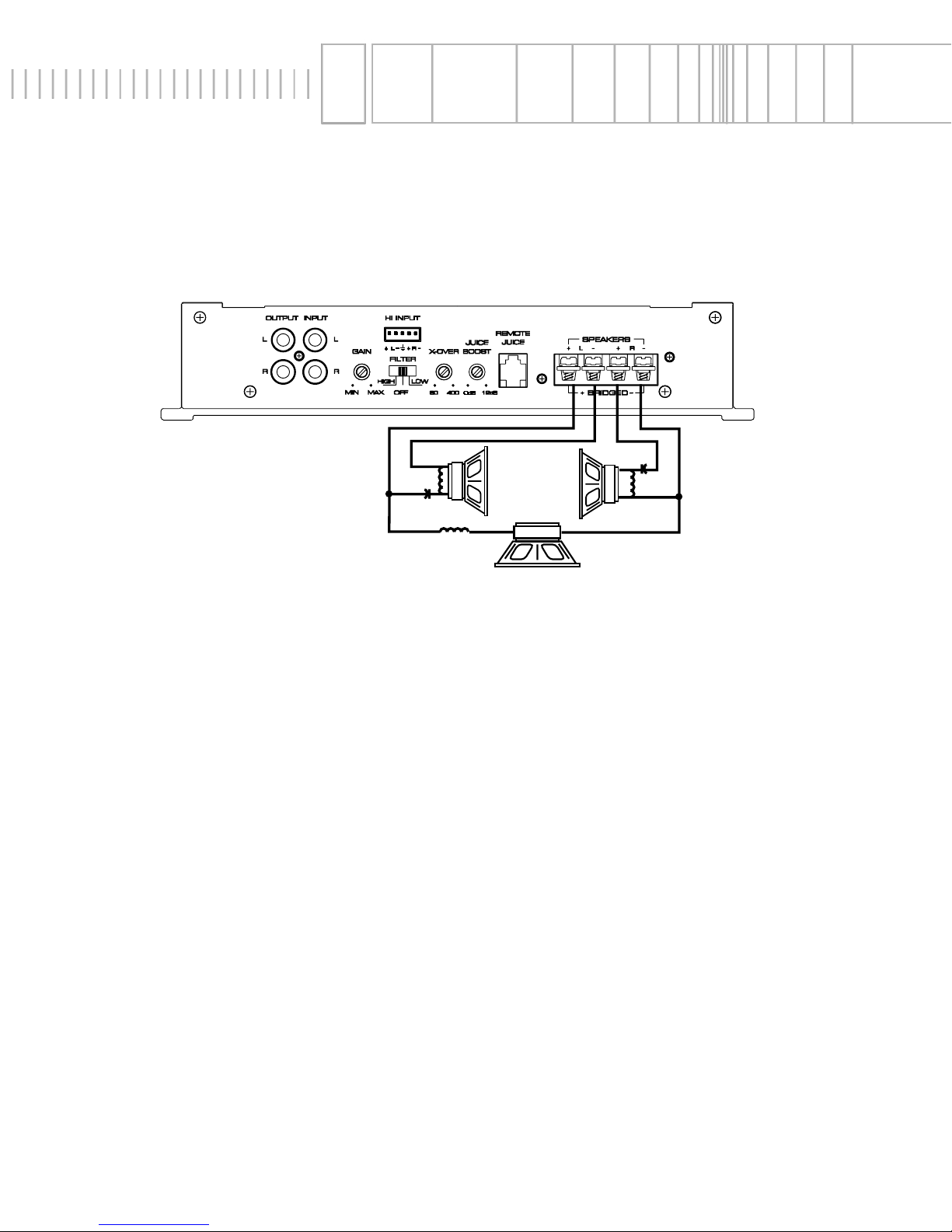
- 18 -
Schéma d’Installation
Amplificateur de Lightning Audio 2 canaux–
+ –
4Ω min.
–
+
–
+
2Ω min. 2Ω min.
InstAllAtion
Opération stéréo/mono (tri mode)
• Les entrées RCA sont connectées aux canaux gauche et droit
• Les Gains des canaux gauche et droit sont réglés de la même manière pour équilibrer le subwoofer
• L'impédance de chaque canal devrait être de minimum 2Ω
• L'impédance du canal mono devrait être de minimum 4Ω
• Les crossover sont introduites sur full range
• Il est conseillé d'utiliser les filtres passifs lorsqu'on fait fonctionner l'amplificateur en tri-mode
• NE connecter AUCUN des câbles HP à la masse au risque d'un fonctionnement instable
• Des filtres passifs sont nécessaires pour un bon fonctionnement en mode stéréo/mono
Page 21

- 19 -
INSTALLATION
• Pour votre sécurité, deéconnectez la borne négative de la batterie du véhicule avant de com-
mencer le montage.
Montage dans l’habitacle
L’installation d’un amplificateur est envisageable dans l’habitacle dès que la convection naturelle est suffisante. Il est
possible de fixer l’amplificateur soud un siège si la hauteur de celui-ci permet au minimum d’avoir trois centimètres audessus du dissipateur thermique.
Alimentation
La connexion B
doit être reliée impérativement via un fusible, directement à la borne positive de la batterie.
La connexion GND
Cette liaison référence l’amplificateur à la masse. La masse électrique du châssis n’a pas en tous points la même qualité. Il vous sera utile de recourir aux compétences d’un professionel pour déterminer le meilleur point. Une fois trouvé, il
faudra débarrasser la tôle de toutes traces de peinture, le raccordement devra se faire par une vis acier (sans traitement de surface).
La connexion REM
Cette connexion est la commande à distance de mise en/hors service. Elle est généralement reliée à la sortie (antenne
électrique de l’autoradio) ou auprès d’une source de douze volts commutée.
Connecteur CINCH
Cette liaison assure la transmission de modulation entre l’autoradio et la source. En raison des faibles signaux véhiculés
dans ces câbles, ceux-ci devront être tenus à l’écart du faisceau électrique du véhicule et des câbles d’alimentation de
l’amplificateur.
Connections haut-parleurs
Les haut-parleurs serons connectés sur cette partie du bornier. Soyez vigilant quant au sens du branchement + et –.
Avertissement: L’impédance globale en mode stéréo ne peut être inférieure à deux W et en mode
ponté à quatre
W.
Contrôle de sensibilité
A la sortie d’usine, l’amplificateur est réglé (valeur qui détermine la meilleure capacité dynamique). La sensibilité est
variable pour adapter l’amplificateur aux différentes sources qui ne possèdent pas le même niveau de sortie.
Ce
réglage est très important, il est déterminant de la qualité de reproduction et de la pérennité de
l’installation.
Méthodologie du réglage
1. Positionnez le réglage de sensibilité au minimum (à l’inverse du sens des aiguilles d’une montre)
2. Ecoutez un passage musical à grande dynamique (solo de guitare basse, etc.) avec le potentiomètre de volume de
la source aul 3/4
3. Doucement dans le sens des aiguilles d’une montre tournez le potentiomètre de sensibilité de l’amplificateur jusqu’à
SOLUTIONS AUX PROBLÈMES
L’amplificateur ne
fonctionne pas
B+ our REM ne sont pas connectés à
une source de 12V
Le bruit est transmis par la source
Bruit rayonné sur les câbles de
modulation
Vérifiez si la batterie est reconnectée et
si le fusible est bon
Insérez un module séparé de télécommande commandant l’amplificateur
Tenir à l’écart les câbles de modulation
du faisceau électrique de la voiture et
de l’alimentation de l’amplificateur
Bruit à l’a mise
en/hors service
Bruit parasite
Symptôme Diagnostic Solution
Page 22
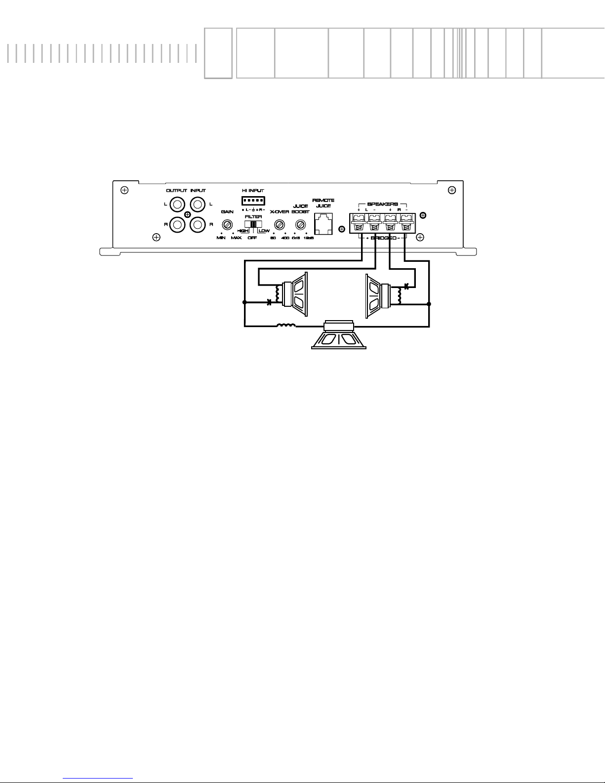
- 20 -
InstAllAtion
Stereo/Mono Operation
• Chinch Eingänge des rechten- und linken-Kanales anschlieben
• Gain -Kontrolle gleich stellen um das Signal des Subwoofer anzugleichen
• Die Impedanz für jeden Kanal sollte minimum 2 Ohm betragen.
• Die Impedanz des Mono Kanales sollte minimum 4 Ohm betragen
• Die Akltivweichen sollten auf jeden Fall im Stereo/Mono Betrieb verwendet werden
• Vermeiden Sie auf jeden Fall eine Erdung der Lautsprecher-Kabel, da sonst ein einwandfreier Betrieb nicht
grantiert werden kann
• Passive Frequenzweichen werden für korrekte Stereo/Mono Operationen benötigt
+ –
4Ω min.
–
+
–
+
2Ω min. 2Ω min.
Installations Beiblatt
2-Kanal Lightning Audio Amplifier –
Deutsch
Page 23

- 21 -
EINBAU
• Zur Sicherheit klemmen Sie den Negativ-Pol der Batterie während des gesamten Einbaues ab.
Im Fahrzeugkofferraum
Der vertikale Einbau der Endstufen, gibt dem Verstärker die beste Kühlung.
Auf der Beifahrerseite
Sollte der Verstärker auf der Beifahrerseite montiert werden, so ist es sehr wichtig für eine ausreichende Kühlung zu
sorgen. Sollte der Verstärker z.B. unter dem Beifahrersitz montiert werden, sollte dem Kühlkörper mindestens ein
Luftspalt von 3 cm bleiben, um so für eine ausreichende Kühlung zu sorgen.
B+ Anschlub
Die Plus-Leitung MUb ca. 40 cm nach dem Plus-Pol der Batterie abgesichert sein. Preparieren Si die Kabellängen und
montieren Sie den Sicherungshalter im Motorraum. ALLE Verbindungen müssen wasserdicht sein.
GND Anschlub
Preparieren Sie Ihr Kabel für Negativ Leitung (Erdung). Preparieren Sie die Anschlubstelle des Erdungskabels, indem
Sie das Metall gründlich reinigen und vom Lack befreien. Befestigen Sie nun die Erdung an dieser Stelle mit einer
Schraube.
REM Anschlub
Verbinden Sie das Ein-und Ausschaltungskontroll-Kabel mit Ihrem Radio (12 Volt positiv). Normalerweise verwenden Sie
hierfür die Ant.-Remote). Sollte Ihr Radio diesen Anschlu
b nicht besitzen, so verwenden Sie eine 12 Volt Spannung, die
Sie durch einen Schalter ein- und ausschalten können.
Eingangs-Anschlübe
Beachten Sie den Anschlussplan und verbinden Sie die Signalkabel mit den Eingangs-Anschluessen des Verstärkers.
Seien Sie sicher, dass die Kabel dicht zusammen und entfernt von stromfuehrenden Kabeln liegen.
Lautsprecher Ausgänge
Verbinden Sie das Lautsprechersystem mit dem Verstärker, indem Sie die Kabel in die entsprechenden Anschluesse
stecken und verschrauben. Beachten Sie hierbei den Anschlussplan, um eine korrekte Polarität zu gewährleisten.
Erden Sie niemals eine der Lautsprecherleitung auf die Masse des Fahrzeuges. Achtung: Die minimale Last von 2
W Stereo und/oder 4W gebrueckt (Mono) darf nicht unterschritten werden.
Eingangsempfindlichkeit
Der Verstärker ist Werkssetig auf eine Eingangsspannung. Die Eingangsempfindlichkeit kann nach Gehoer verstellt
werden, wenn die Ausgangsspannung des Steuergerätes hoeher oder niedriger ist. Gehen Sie wie folgt vor.
1. Drehen Sie die Eingangsempfindlichkeit auf ein Minimum (gegen den Uhrzeigersinn).
2. Speilen Sie einen Musiktitel mit einer sehr hohen Dynamik und drehen Sie die Lautstärkekontrolle des Steuergerätes
auf ä der Maximallautstärke.
3. Jetzt verstellen Sie die Eingangsempfindlichkeit des Verstärkers soweit (im Uhrzeigersinn drehen), bis Sie eine
Verzerrung des Signals wahrnehmen. Danach sollte ie Empfindlichkeit wieder soweit zurueck gedreht werden
(gegen den Uhrzeigersinn), bis die Verzerrungen verschwindern.
Syptom Diagnose Fehlerbehebung
FEHLERSUCHE
Verstärker schaltet nicht ein
Die B+ oder Rem. Spannung liegt nicht
zwischen 10.5 und 15.5 Volt
Verstärker ist nicht korrekt geerdet
Die XCard ist falsch oder gar nicht in den
entsprechenden Socket gesteckt.
Stoerungen strahlen in die Signalkabel
Kontrollieren Sie die Lichtmaschine,
Batterie, Sicherung und die Kable.
Repaireren Sie diese, wenn noetig
Kontrollieren Sie die Kabel und reparieren
Sie diese, wenn noetig
Kontrollieren Sie die Installation der XCard
und ändern Sie diese, wenn noetig
Verlegen Sie die Kabel weit entfernt von
stromfuehr
Verstä rker
Einschaltgeräusch
(Turn-On Pop)
Lichtmaschinen
Summen
Page 24
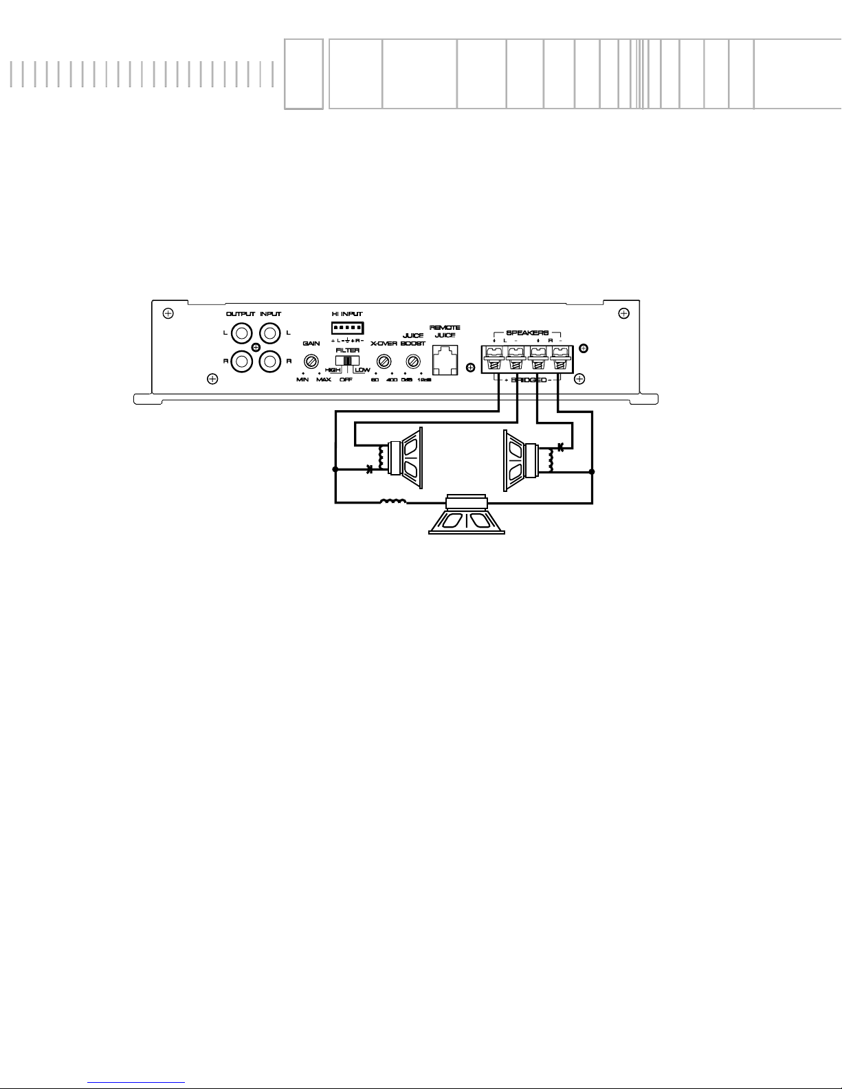
- 22 -
Istruzioni di Installation
Amplificatore di Lightning Audio a 2 canali – Italiano
InstAllAtion
Stereo/Mono Operation
• Ingressi RCA collegati sia al canale destro sia al sinistro
• Gain (controllo di sensibilitá) regolati in modo identico per bilanciare il subwoofer
• L'impedenza di ciascun canale deve essere minimo 2Ω
• L'impedenza per il canale mono deve essere minimo 4Ω
• La scheda crossover deve essere in posizione Full Range
• Nel funzionamento Stereo/Mono simultaneo devono essere impiegati i crossover passivi
• Non cortocircuitare a massa nessun cavo degli altoparlanti, potrebbe portare ad un funzionamento irregolare
• Crossover passivi sono indispensabili per un corretto funzionamento stereo/mono
+ –
4Ω min.
–
+
–
+
2Ω min. 2Ω min.
Page 25

- 23 -
INSTALLAZIONE
• Per sicurezza, scollegare il polo netativo della batteria dell’auto prima di iniziare l’installazione.
Nel Bagagliaio
Montando l’amplificatore su una superficie in verticale con le alette direzionate dall’alto verso il basso si garantirá un
miglior raffreddamento dell’amplificatore.
Nel’abitacolo
Montare l’amplificatore nell’abitacolo si avrá un funzionamento regolare se si garantisce un flusso d’aria sufficiente. Per
l’installazione sotto un sedile, é necessario avere uno spazio di almeno 3 cm attorno a tutto l’amplificatore.
Terminale B+ (cavo positivo)
Il cavo positivo deve essere protetto da un fusibile a non piú di 45 cam dalla batteria. Terminare il cavo e installare il
fusibile nel vano motore. Tutte le connessioni devono essere a prova d’acqua.
Terminal GND (cavo negativo)
Decidere la lunghezza del cavo e terminarlo. Preparare la massa grattando la vernice dal telaio dell’auto ed eliminando
tracce di olio o sporco. Fissare il cavo di massa al telaio con una vite.
Terminal REM (Consenso di accensione)
Collegare il cavo REM ad un positivo present solo ad autoradio accessa (normalmente il cavo pilota dell’antenna elettrica o il cavo accessori dell’autoradio). Se la sorgente non dovesse essere equipaggiata con queste uscite, la soluzione
raccomandabile é di inserire un interruttore su un cavo positivo e connettersi all’amplificatore.
Connettori di ingresso
Seguendo lo schema collegate i cavi di segnale agli appropriati terminali di ingresso dell’amplificatore. Assicuratevi che
i cavi di segnale siano passati vicini tra loro e lontano da cavi ad alta corrente.
Connettori degli altoparlanti
Collegate il sistema di altoparlanti inserendo i cavi nei terminali corrispondenti e serrate le viti. Seguite lo schema per
l’ottimale colle gamento delle polaritá.
Non cortocircuitate a massa nessun cavo degli altoparlanti,
potrebbe verificarsi un anomalo comportamento dell’amplificatore. ATTENZIONE; questo amplificatore non é raccomandato per impedenze inferiori ai 2 ohm stereo w/o 4 ohm mono a ponte.
Controlli della sensibilitá
L’amplificatore é regolato dalla casa per un ottimale rendimento dinamico. Il lilvello di ingresso puó essere regolato
anche ad orecchio quando si impiega una sorgente con uscita superiore od inferiore. Seguite questa procedure:
1. Portate il controllo della sensibilitá al minimo (senso antiorario)
2. Suonate un brano musicale con elevato contenuto dinamico portando il volume della sorgente a circa 3/4
3. Aumentate lentamente il livello di ingresso dell’amplificatore e posizionatelo subito prima dell’insorgere di distorsione
o quando il livello generale vi appaia confortevole
RISOLUZIONE DEI PROBLEMI
L’ampificatore non si
accende
Il B+ o il REM n on hanno una tensione
compresa tra i 10,5 e 15,5 volt o nessuna tensione é presente
L’amplificatore non é correttamente a
massa
Verficate l’alternatore, la batteria, i
fusibilit, il cablaggio e riparate
quanto necessario
Controllate il cablaggio e riparat se
necessario
Se il bump si elimina disconnettendo gli ingressi, collegate un modulo
di accensione
Ristendete i cavi di segnale lontano
da cavi ad alta corrente
Rumore dell’
amplificatore
(bump di accensione)
Rumore dal motore
Picchi di tensione provenienti dalla sorgente entrano dall’ingresso dell’amplificatore
Il rumore si propagna nei cavi di segnale
Sintomo Diagnosi Rimendo
Page 26
- 24 -
DEUTSCH ITALIANO
ESPAÑOL
Please contact your local Authorized
Lightning Audio Dealer for information
on Warranty Policies and Technical Suppor
t.
ENGLISH
FRANÇAIS
Contattate il vostro rivenditore autor-
izzato Lightning Audio per infor-
mazioni sulle condizioni di garanzia e
per il supporto tecnico.
Por favor contacte al Distribuidor
Autorizado Lightning Audio en su localidad para información sobre Políticas de
Garantía Soporte Técnico.
Bitte Fragen Sie Ihren autorisierten
Lightning Audio Händler über Informationen,
die die Garantie oder technische Probleme
betreffen.
Veuillez contacter votre distributeur
Lightning Audio agréé pour toute infor-
mation concernant les modalités de
garantie et le support technique.
Page 27

- 25 -
Limited
WArrAnty InformAtion
Lightning Audio offers a limited warranty on products on the following terms:
•
Length of Warranty
Speakers
One year parts and labor warranty. Requires proof of purchase
Amplifiers
If installed by an authorized Lightning Audio dealer, two years parts and labor, requires proof of purchase/
installation. If purchased from authorized dealer and installed by a third party, one year parts and labor.
Requires proof of purchase.
PC1, FM1
One year parts and labor. Requires proof of purchase.
•
What is Covered
This warranty applies only to Lightning Audio products sold to consumers by Authorized Lightning Audio Dealers in the
United States of America or its possessions. Product purchased by consumers from an Authorized Lightning Audio
Dealer in another country are covered only by that country’s Distributor and not by Lightning Audio.
•
Who is Covered
This warranty covers only the original purchaser of Lightning Audio product purchased from an Authorized Lightning
Audio Dealer in the United States. In order to receive service, the purchaser must provide Lightning Audio with a copy
of the receipt stating the customer name, dealer name, product purchased and date of purchase.
•
Products found to be defective during the warranty period will be repaired or replaced (with a product deemed to be
equivalent) at Lightning Audio’s discretion.
•
What is Not Covered
1. Damage caused by accident, abuse, improper operations, water, theft
2. Any cost or expense related to the removal or reinstallation of product
3. Service performed by anyone other than Lightning Audio or an Authorized Lightning Audio Service Center
4. Any product which has had the serial number defaced, altered, or removed
5. Subsequent damage to other components.
6. Any product purchased outside the U.S.
7. Any product not purchased from an Authorized Lightning Audio Dealer
•
Limit on Implied Warranties
Any implied warranties including warranties of fitness for use and merchantability are limited in duration to the period of
the express warranty set forth above. Some states do not allow limitations on the length of an implied warranty, so this
limitation may not apply. No person is authorized to assume for Lightning Audio any other liability in connection with the
sale of the product.
•
How to Obtain Service
Please call 1-888-881-8186 for Lightning Audio Customer Service. You must obtain an RA# (Return Authorization number) to return any product to Lightning Audio. You are responsible for shipment of product to Lightning Audio. Always
include Proof of Purchase. Mark RA# on outside of shipping carton.
Ship to: Electronics
Lightning Audio
Warranty Repair Department
2055 E. 5th Street
Tempe, AZ 85281
RA#:_________________
Page 28

Lightning Audio
955 N. Fiesta Blvd, Suite 4
Gilbert, Arizona 85233 U.S.A.
In U.S.A., (480) 966-8278
08/00 M.J.T
MADE IN CHINA
 Loading...