

Page 1
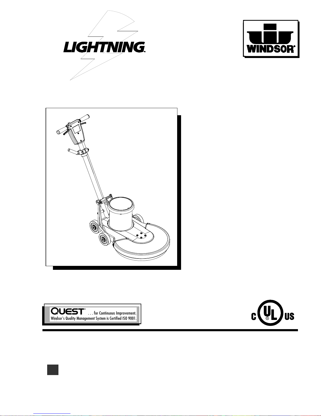
HIGH SPEED BURNISHER
Operating Instructions (ENG)
Read these instructions before using the machine.
MODEL: LB1500
10090160
H
86037180 12/29/06
PRV NO. 980101
Page 2

MACHINE DATA LOG/OVERVIEW
LB1500 86037180 12/29/06
MODEL______________________________
DATE OF PURCHASE ________________
SERIAL NUMBER____________________
2
For the name and address of your dealer contact: Windsor Industries
YOUR DEALER
Name: __________________________________________________________________________________________________
Address: _______________________________________________________________________________________________
Phone Number: _________________________________________________________________________________________
Page 3

TABLE OF CONTENTS
LB1500 86037180 12/29/06
3
Machine Data Log/Overview.........................2
Table of Contents..........................................3
HOW TO USE THIS MANUAL
How to use this Manual.................................1-1
SAFETY
Important Safety Instructions........................2-1
Hazard Intensity Level. .................................2-2
Grounding Instructions..................................2-3
OPERATION
Technical Specifications ...............................3-1
Handle Installation ........................................3-2
Operation......................................................3-3
Pad Driver Installation...................................3-4
MAINTENANCE
Machine Troubleshooting..............................4-1
Wiring Diagram/Service Schedule................4-2
GROUP PARTS LIST
Motor Group..................................................5-1
Frame Group.................................................5-3
Drive/Pad Lock Group...................................5-5
Handle Group................................................5-7
Wiring Group.................................................5-9
Suggested Spare Parts...............................5-11
Warranty ..................................................... 5-12
Page 4

HOW TO USE THIS MANUAL
LB1500 86037180 12/29/06
This manual contains the following sections:
- HOW TO USE THIS MANUAL
- SAFETY
- OPERATIONS
- MAINTENANCE
- PARTS LIST
The HOW TO USE THIS MANUAL section will tell
you how to find important information for ordering
correct repair parts.
Parts may be ordered from authorized Windsor
dealers.
When placing an order for parts, the
machine model and machine serial number are
important. Refer to the MACHINE DATA box which
is filled out during the installation of your machine.
The MACHINE DATA box is located on the inside
of the front cover of this manual.
1-1
The SAFETY section contains important
information regarding hazard or unsafe practices
of the machine. Levels of hazards is identified that
could result in product or personal injury, or severe
injury resulting in death.
The OPERATIONS section is to familiarize the
operator with the operation and function of the
machine.
The MAINTENANCE section contains preventive
maintenance to keep the machine and its
components in good working condition.
The PARTS LIST section contains assembled
parts illustrations and corresponding parts list. The
parts lists include a number of columns of
information:
- REF – column refers to the reference
number on the parts illustration.
- PART NO. – column lists the part
number for the part.
- PRV NO. – reference number.
- QTY – column lists the quantity of the
part used in that area of the machine.
- DESCRIPTION – column is a brief
description of the part.
- SERIAL NO. FROM – column
indicates the first machine the part
number is applicable to. When the
machine design has changed, this
column will indicate serial number of
applicable machine. The main
illustration shows the most current
design of the machine. The boxed
illustrations show older designs.
MODEL _____________________________________
DATE OF PURCHASE ________________________
SERIAL NUMBER ____________________________
SALES REPRESENTATIVE # ___________________
DEALER NAME ______________________________
OPERATIONS GUIDE NUMBER __________________
PUBLISHED ________________________________
- NOTES – column for information not
noted by the other columns.
NOTE: If a service or option kit is installed on your
machine, be sure to keep the KIT INSTRUCTIONS
which came with the kit. It contains replacement
parts numbers needed for ordering future parts.
NOTE: The number on the lower left corner of the
front cover is the part number for this manual.
Page 5

IMPORTANT SAFETY INSTRUCTIONS
When using an electrical appliance, basic precaution
must always be followed, including the following:
READ ALL INSTRUCTIONS BEFORE USING THIS MACHINE.
To reduce the risk of fire, electric shock, or injury:
!
WARNING:
Use only indoors. Do not use outdoors or expose to rain.
Use only as described in this manual. Use only manufacturer’s recommended components and attachments.
If the machine is not working properly, has been dropped, damaged, left outdoors, or dropped into water,
return it to an authorized service center.
Do not operate the machine with any openings blocked. Keep openings free of debris that may reduce
airflow.
Machine can cause a fire when operating near flammable vapors or materials. Do not operate this machine
near flammable fluids, dust or vapors.
This machine is suitable for commercial use, for example in hotels, schools, hospitals, factories,
shops and offices for more than normal housekeeping purposes.
Maintenance and repairs must be done by qualified personnel.
During operation, attention shall be paid to other persons, especially children.
The machine shall only be operated by instructed and authorized persons.
When leaving unattended, unplug the machine.
Do not handle the plug or machine with wet hands.
Do not unplug machine by pulling on cord. To unplug, grasp the plug, not
the cord.
Do not use with damaged cord or plug. Follow all instructions in this manual concerning grounding the
machine.
Do not pull or carry by cord, use cord as a handle, close a door on cord, or pull cord around sharp e dges or
corners.
Do not pull/run machine over cord. Keep cord away from heated surfaces.
Connect to a properly grounded outlet. See Grounding Instructions.
SAVE THESE INSTRUCTIONS
2-1
LB1500 86037180 12/29/06
Page 6

HAZARD INTENSITY LEVEL
LB1500 86037180 12/29/06
2-2
The following symbols are used throughout this guide as indicated in their descriptions:
HAZARD INTENSITY LEVEL
There are three levels of hazard intensity identified by signal words -WARNING and CAUTION and FOR
SAFETY. The level of hazard intensity is determined by the following definitions:
WARNING - Hazards or unsafe practices which COULD result in severe personal injury or death.
! WARNING
! CAUTION
CAUTION - Hazards or unsafe practices which could result in minor personal injury or product or
property damage.
FOR SAFETY: To Identify actions which must be followed for safe operation of equipment.
Report machine damage or faulty operation immediately. Do not use the machine if it is not in proper
operating condition. Following is information that signals some potentially dangerous conditions to the
operator or the equipment. Read this information carefully. Know when these conditions can exist.
Locate all safety devices on the machine. Please take the necessary steps to train the machine
operating personnel.
FOR SAFETY:
DO NOT OPERATE MACHINE:
Unless Trained and Authorized.
Unless Operation Guide is Read and understood.
In Flammable or Explosive areas.
In areas with possible falling objects.
WHEN SERVICING MACHINE:
Avoid moving parts. Do not wear loose clothing; jackets, shirts, or sleeves when working on the
machine. Use Windsor approved replacement parts.
Page 7
GROUNDING INSTRUCTIONS
LB1500 86037180 12/29/06
2-
THIS PRODUCT IS FOR COMMERCIAL
USE ONLY.
3
ELECTRICAL:
In the USA this machine operates on a 15 amp
nominal 120V, 60 hz, A.C. power circuit. The
amp, hertz, and voltage are listed on the data
label found on each machine. Using voltages
above or below those indicated on the data label
will cause serious damage to the motors.
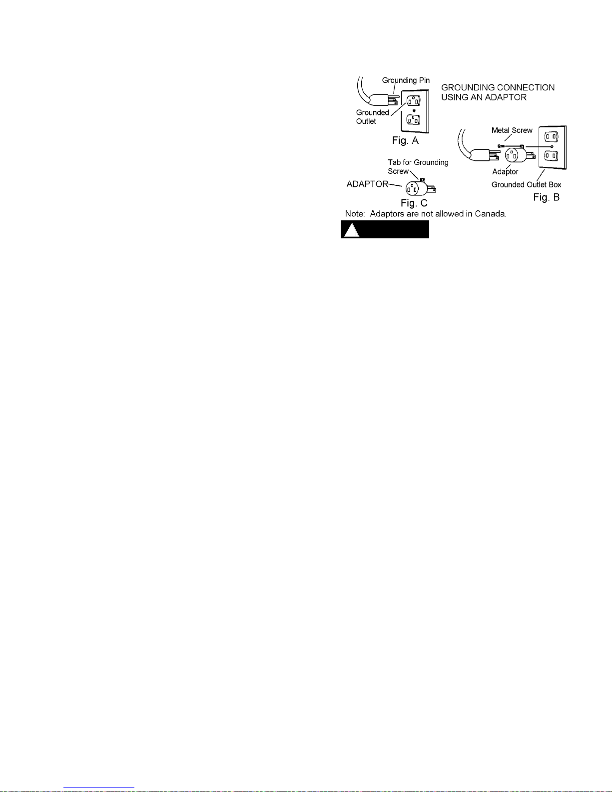
GROUNDING INSTRUCTIONS:
This appliance must be grounded. If it should
malfunction or break down, grounding provides
a path of least resistance for electric current to
reduce the risk of electric shock. This appliance
is equipped with a cord having an equipmentgrounding conductor and grounding plug. The
plug must be inserted into an appropriate outlet
that is properly installed and grounded in
accordance with all local codes and ordinances.
This appliance is for use on a nominal 120-volt
circuit, and has a grounded plug that looks like
the plug in “Fig. A”. A temporary adaptor that
looks like the adaptor in “Fig . C” may be used
to connect this plug to a 2-pole receptacle as
shown in “Fig. B”, if a properly grounded outlet
is not available. The temporary adaptor should
be used only until a properly grounded outlet
(Fig. A) can be installed by a qualified
electrician. The green colored rigid ear, lug, or
the like extending from the adaptor must be
connected to a permanent ground such as a
properly grounded outlet box cover. Whenever
the adaptor is used, it must be held in place by a
metal screw.
! WARNING
Improper connection of the equipmentgrounding conductor can result in a risk of
electric shock. Check with a qualified
electrician or service person if you are in
doubt as to whether the outlet is properly
grounded. Do not modify the plug provided
with the appliance - if it will not fit the outlet,
have a proper outlet installed by a qualified
electrician.
Page 8
TECHNICAL SPECIFICATIONS
LB1500 86037180 12/29/06
3-1
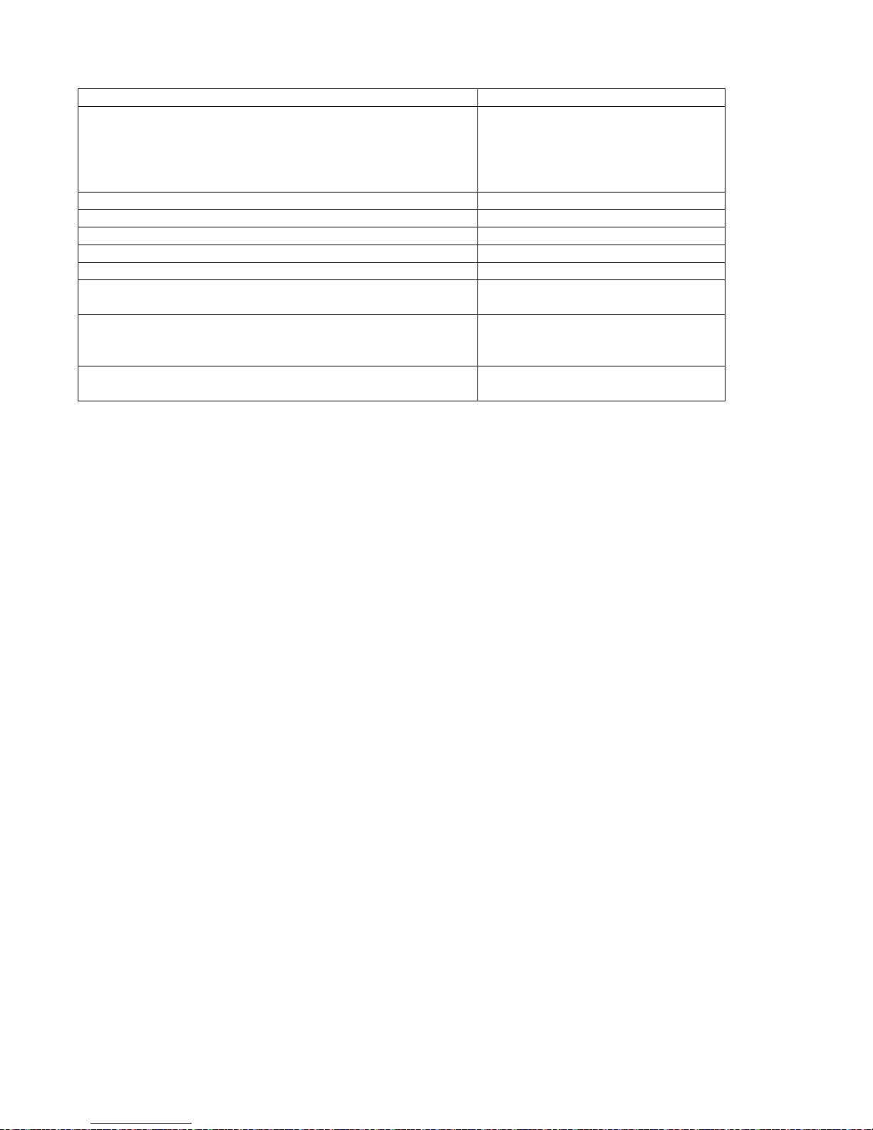
ITEM DIMENSION/CAPACITY
Construction Heavy-duty die cast aluminum deck
with heavy-duty rubber bumper,
tubular steel adjustable handle with
die cast aluminum handle housing
and belt driven pad.
Motor 1.75 hp
Pad speed 1500 rpm
Electrical system 115 volts, 60 Hz
Cable 50’ (23 m), 14/3, built in cord wrap
Switches Dual levers with safety lock
Wheels Four 5” (12.7 cm) dia., 1.25” (3 cm)
wide, non-marking tread
Handle 1.5” (4 cm) tubular steel,
adjustable, easy to use thumb
activated safety lock
Dimensions (L x W x H) 31.5” (80 cm) X 21.5” (54 cm) X
48.5” (123 cm)
NOTE: Always use a pad which has been designed for electric ultra high speed burnishing of at
least 2000 rpm.
The sound pressure level at the operator’s ear was measured to be 70 dBA. This was a nearfield,
broad-band measurement taken in a typical industrial environment on a tile floor. This appliance
contains no possible source of impact noise. The instantaneous sound pressure level is below 63
Pa.
Page 9
HANDLE INSTALLATION
2
HANDLE
RECEPTACLE
4
HANDLE
ASSEMBLY
5
DECK
ASSEMBLY
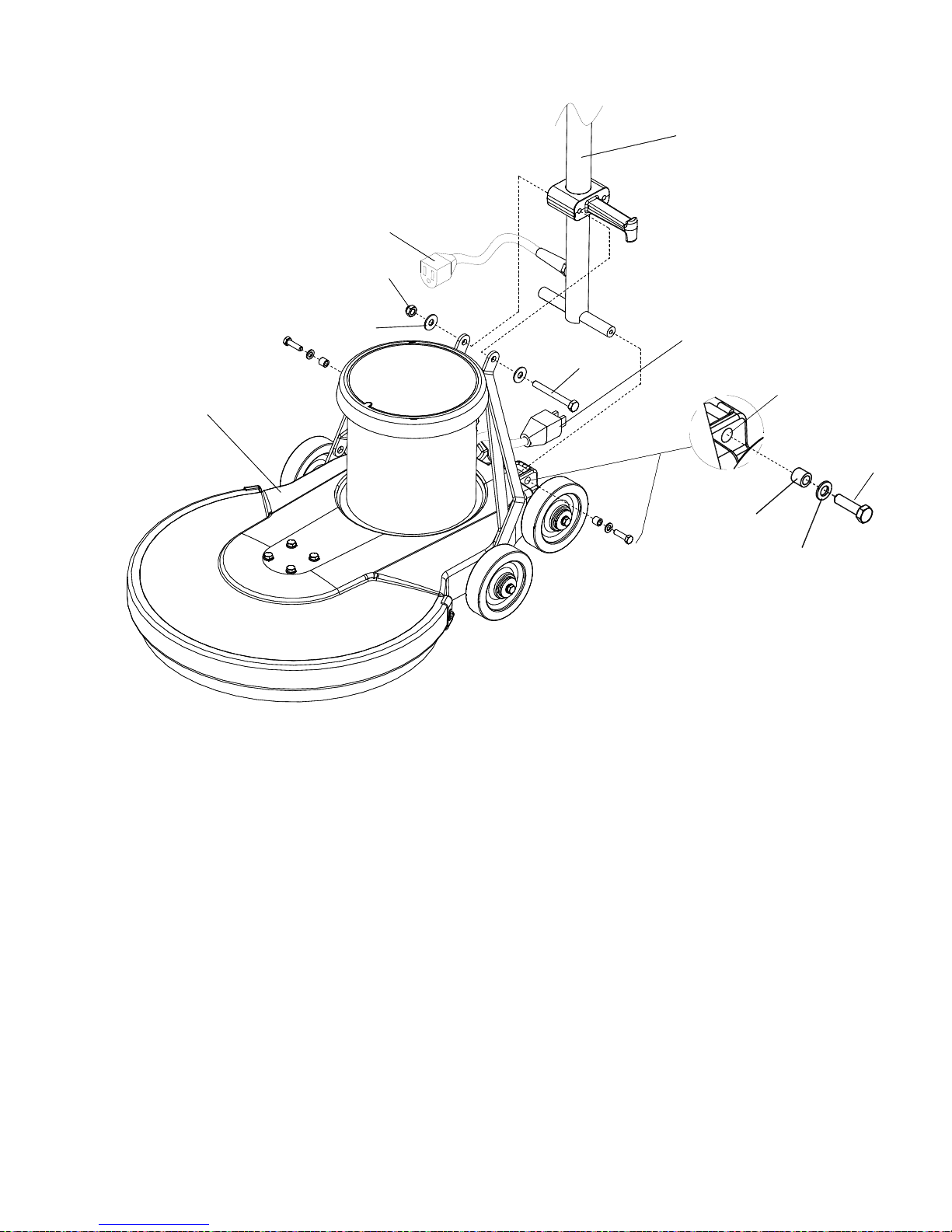
The machine is shipped with handle unassembled.
Follow these steps for installation:
1. Remove handle and deck assembly from
carton.
2. Attach handle assembly to base using
hardware kit (86219680 PRV NO. 47331)
(attached to handle in a plastic bag) items 1,
2, and 3.
NOTE: The spacers (items 1) are required for the
correct operation of the handle. The spacers are
positioned completely inside the pivot holes in the
casting, and are held in place by tightening the
bolts and washers (items 2 and 3) against the
spacer.
LB1500 86037180 12/29/06
MOTOR
PLUG
6
PIVOT
HOLE
3
1
SEE NOTE
2
3. Remove bolt, nut and washers (items 4, 5 and
6) from lower block on handle assembly. Attach
links as shown. Tighten bolt and nut securely,
then back off 1/4 to 1/2 turn.
4. Check handle for movement up and down.
5. Plug motor cord into handle cord receptacle.
3-
Page 10
OPERATION
LB1500 86037180 12/29/06
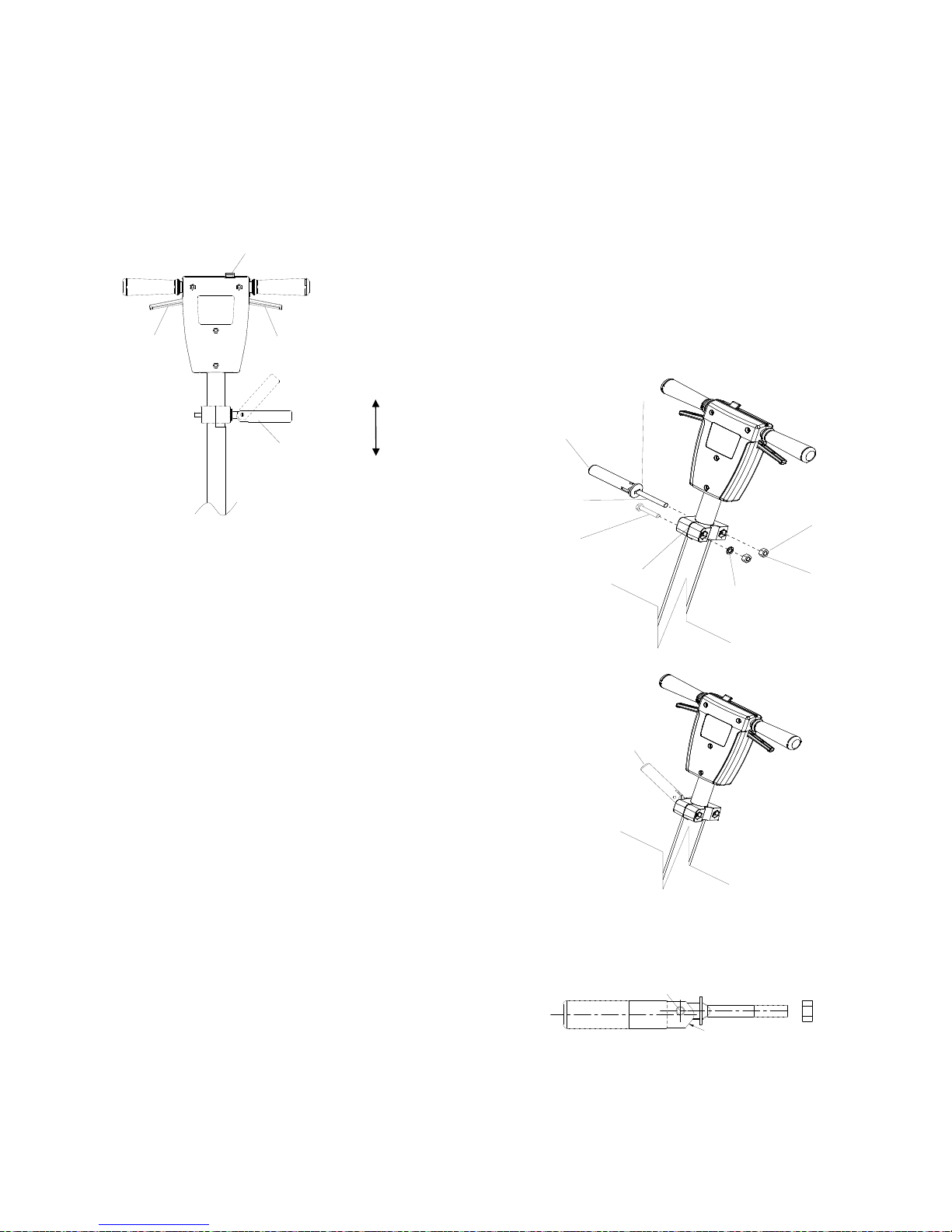
CONTROLS
1. Safety Lock – Prevents unintended operation of
the machine.
2. Switch Levers – Turns machine on/off.
3. Adjustment Handle – Allows the handle to be
adjusted to a comfortable operating position.
3-3
The handle adjust bar (86215130 - PRV
NO.14344) for the polishers are individually
preset at the factory for optimum locking
efficiency and minimum effort of engaging. It
should not be necessary to adjust the handle
adjust bar unless the relationship of the handle
adjust bar nut (86136360 - PRV NO. 57275) or
fixed clamp bolt (86136700 – PRV NO. 70692)
and their corresponding nuts (86136360 –
PRV NO. 57275) and washer (86010720 –
PRV NO. 87086) have been disturbed. The
handle can be positioned to be locked with the
handle adjust bar pointing either up or down.
In order to change the position the handle and
bolt must be removed and rotated 180
degrees. It is incorrect to make it lock opposite
from the way it was assembled by applying
more force to the nut. From the factory the
locking is in the up position when the machine
handle is locked. The pivot pin (86222560 –
PRV NO. 66334) on the handle adjust bar is
off center, in relationship of the screw to the
axis of the (see drawing). To adjust handle
adjust bar, tighten nut on handle while in the
locked position. The handle is locked when the
screw is to the outside of the machine and the
flat on the opposite side of the handle is flush
to the bracket.
1. To adjust handle lock, tighten nut on handle while
in the locked position. Optimum locking force and
ease of locking is accomplished when the locking
lever nut is set to a torque of 30 to 50 inch pounds
in the locked position.
2. Gap between clamp halves at the front should be
to the gap in rear when the handle adjust bar is
adjusted properly and in the locked position (gap
approximately 1/16").
22
1
3
LOCK
UNLOCK
86010720
PRV N O . 67430
86223550
86136700
PRV N O . 70692
2
86136360 (2)
PRV N O . 57275
1
PRV N O . 87086
86215130
PRV NO. 14344
86225710
PRV N O . 87202
SHOWN HANDLE IS
IN LOCK POSITION
LOCKING SIDE FLAT
86222560
PRV NO. 66334
PIVOT PIN C
L
HANDLE C
L
Page 11
OPERATION
LB1500 86037180 12/29/06
OPERATION
For indoor use only.
3-
4
When using the pad, always keep the machine
moving when in contact with the floor.
High starting torque. Hold machine firmly with
both hands.
1. Ensure that the pad driver is in good shape.
Install or change pad if necessary.
2. Plug the machine into a wall outlet as
described in the grounding instructions.
3. Lower the handle by unlocking the adjustment
handle and moving the handle into position.
Relock the handle when it is in a comfortable
position.
Insure that handle is locked in position before
starting machine.
4. Push the safety lock forward, unlocking the
switch levers.
5. With the safety lock forward, squeeze one or
both of the switch levers, turning the machine
on. (These levers can be operated
independently of each other). The safety lock
will not re-engage until both levers are
released.
6. To stop the machine, release the switch
levers.
7. Do not let machine rest on pad. When
finished with the machine, return handle to the
storage position.
NOTE: The machine is equipped with a circuit
breaker to protect the motor in the event an
overload condition occurs. The circuit breaker is
located on the rear of the motor. Push the reset
button to restart the machine. If the breaker trips
again, correct the cause of overloading before
proceeding.
DAILY MAINTENANCE
1. Inspect power cord for wear. To prevent
electrical shock replace cords with frayed or
cracked insulation immediately.
! CAUTION
2. Place machine in the storage position.
3. Check pad condition. Change if soiled or torn.
! WARNING
PAD INSTALLATION
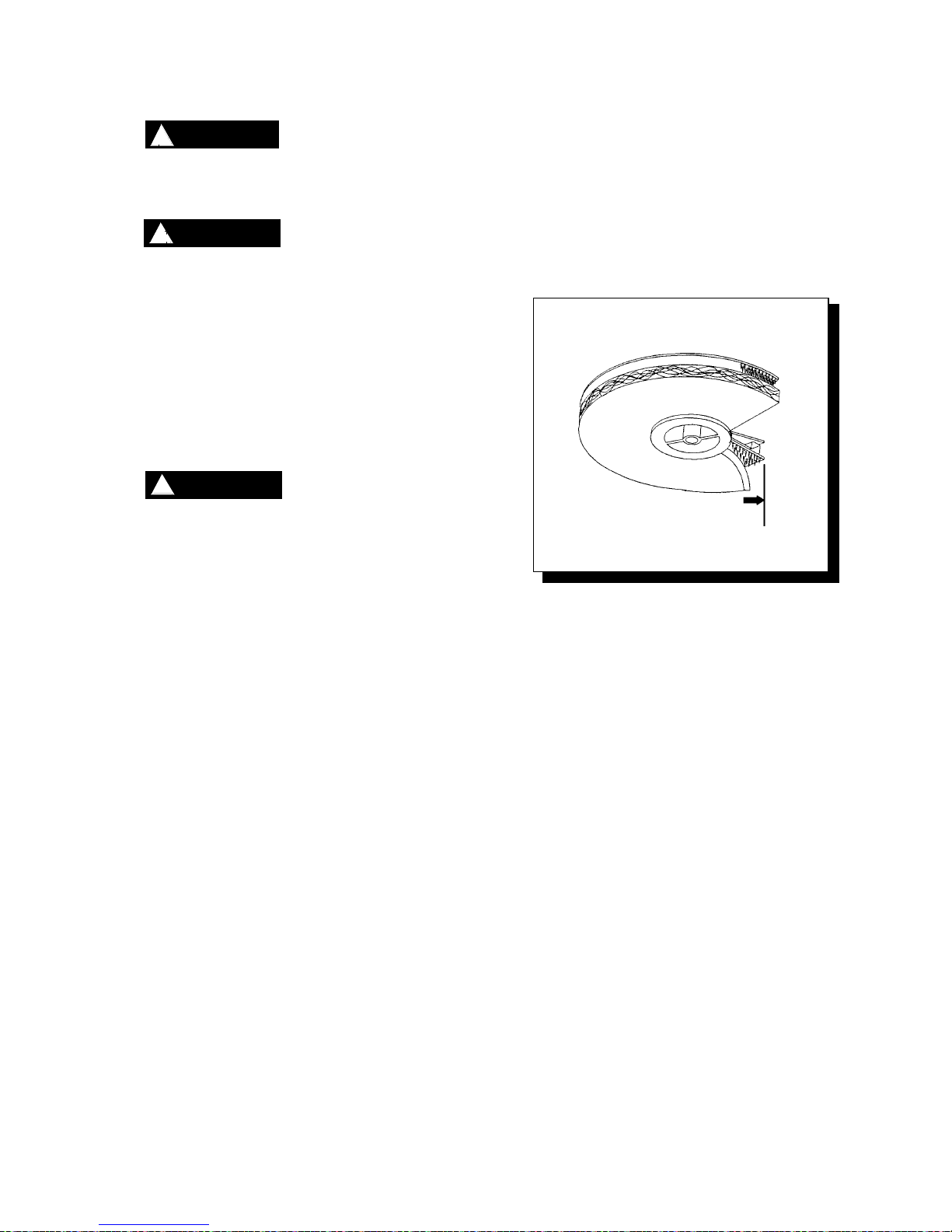
1. Lay machine back, exposing the under side.
Ensure pad is centered on pad driver. Pull
pad to edge of pad driver in several
directions to check for proper engagement.
! WARNING
NOTE: Use care when replacing center lock
ss threading. to prevent cro
Page 12
TROUBLESHOOTING
LB1500 86037180 12/29/06
4-1
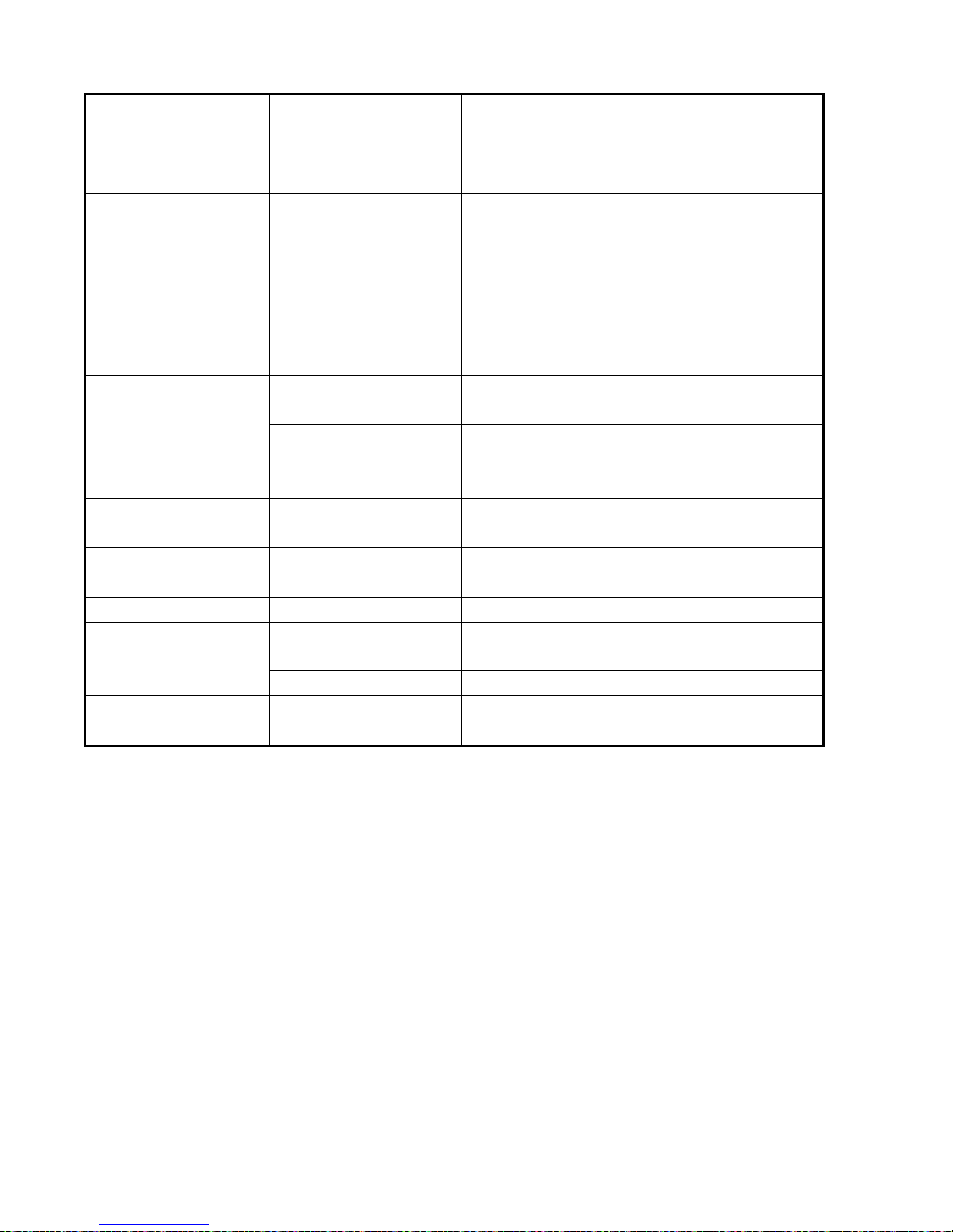
PROBLEM CAUSE SOLUTION
Machine will not run
Circuit breaker tripped in
building.
Check and reset.
Power switch failure. Test switch for continuity and replace if necessary.
Tripped circuit breaker. Reset.
Faulty power cord. Replace.
Fuse in motor is blown.
Replace. CAUTION: To reduce the risk of electrical
shock, unplug the machine before opening fuse
holder. Fuse will only open under extreme
conditions. Investigate cause before replacing.
Electrical shock Equipment not grounded. Follow g ro unding instructions exactly.
Receptacle not grounded. Have an electrician inspect building’s wiring.
Internal wiring problem
Ensure that the machine wiring matches the
appropriate wiring diagram. Replace any wires or
components that are short-circuiting.
Repeated circuit
breaker tripping
Mechanical problem.
Higher amp draws indicate a mechanical problem,
find the problem before using the machine.
Faulty circuit breaker.
Test circuit for continuity. Replace circuit breaker if
necessary.
Excessive vibration Pad not centered. Re-center pad.
Damaged or unevenly
worn pad.
Replace pad. Do not rest machine on pad when not
in use.
Damaged pad driver. Replace.
Pad does not turn but
motor is running
Belt is loose or broken Adjust or replace belt.
Page 13
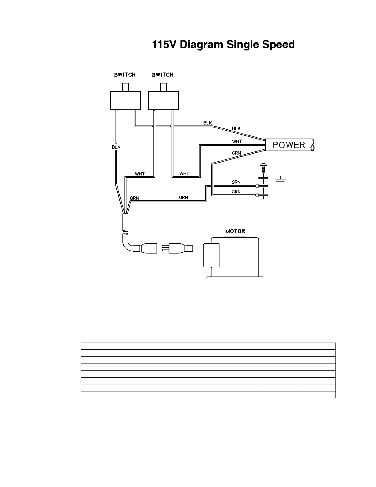
WIRING DIAGRAM/SERVICE SCHEDULE
LB1500 86037180 12/29/06
4-2
SERVICE SCHEDULE
MAINTENANCE DAILY MONTHLY
Check pad wear to prevent buildup of chemicals
*
Check pad driver system for damage
*
Check handles, switches, and knobs for damage
*
Store with pad off the floor
*
Check all bearings for noise
*
Check skirt/bumpers for damage and replace as necessary
*
Check overall performance of machine
*
Page 14
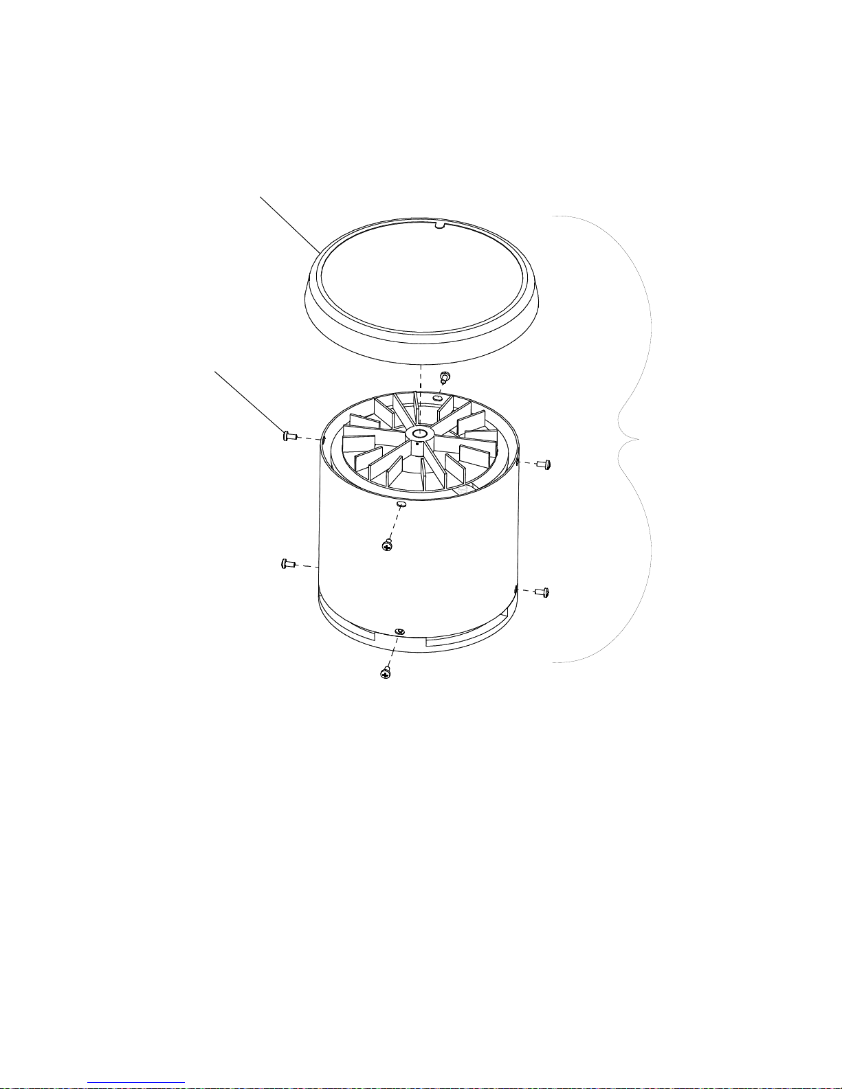
MOTOR GROUP
LB1500 86037180 12/29/06
2
1
3
5-1
Page 15
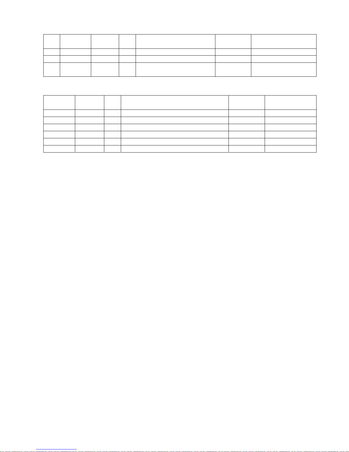
MOTOR GROUP
LB1500 86037180 12/29/06
5-
2
REF PART NO. PRV NO. QTY DESCRIPTION
SERIAL NO.
FROM
NOTES:
1 86217500 27892
1
COVER ASM, MOTOR
2 86223680 70700 8 SCR, M5 X .8 X 10 PHMS BLK
3 86222060 53249 1 MOTOR, 115V 1.75 HP
INCLUDES
ITEM 1 & 2
MOTOR COMPONENTS (NOT SHOWN)
PART NO. PRV NO. QTY DESCRIPTION
SERIAL NO.
FROM
NOTES:
86216720 140694
1 CIRCUIT BREAKER, 25 AMP MP/MB
86223390 67488
1 RECTIFIER, 50A 600V BRIDGE
86001820 14404
1 BRUSH SET MOTOR (PKG OF 4)
86003660 34378
1 FUSE
86003670 34379
1 FUSE HOLDER
86001020 09135
2 BEARING, MOTOR
Page 16
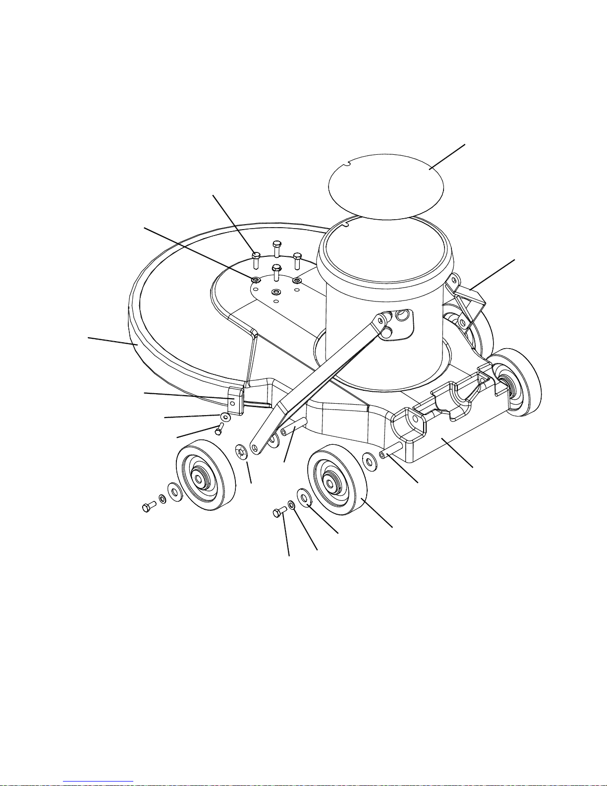
FRAME GROUP
LB1500 86037180 12/29/06
1
13
7
8
10
15
12
11
6
9
5
4
14
7
3
2
5-3
Page 17
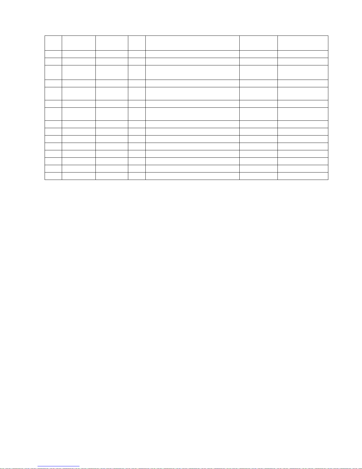
FRAME GROUP
LB1500 86037180 12/29/06
5-
4
REF PART NO. PRV NO. QTY DESCRIPTION
SERIAL NO.
FROM
NOTES:
1 86220050 500766
1 LABEL, LIGHTNING 1500 MAIN
2 86215460 140397 2 BRACKET, HANDLE LINK
3 86217630 29229BLU 1 DECK, 20 IN BURNISHER, BLUE
4 86214930 03111 1 AXLE, MAIN POLISHER
5 86226020 89206 4
WHEEL, 5D X 1.25 X 13MM ID
GRY
6 86225720 87203 8 WASHER, 14MM ID X 36MM OD
7 86137280 87054 8
WASHER, M8 FLAT DIN125A
PLTD
8 86136640 70262 4 SCR, M8 X 20 HHMS PLTD
9 86214950 03116 1 AXLE, MAIN BURNISHER
10 86276570 70691 2 SCR, M6 X 25 HHMS BLK
11 86137340 87211 2 WASHER, M6 FLAT BLK
12 86216600 27871 2 CAP, EXTRUSION
13 86216360 14423 1 BUMPER, EXTRUSION 44.30 IN
14 86288730 70184 4 SCR, M8 X 25HHCS
15 86222270 57276 2
NUT, PUSH FLAT RD .51 ID
Page 18
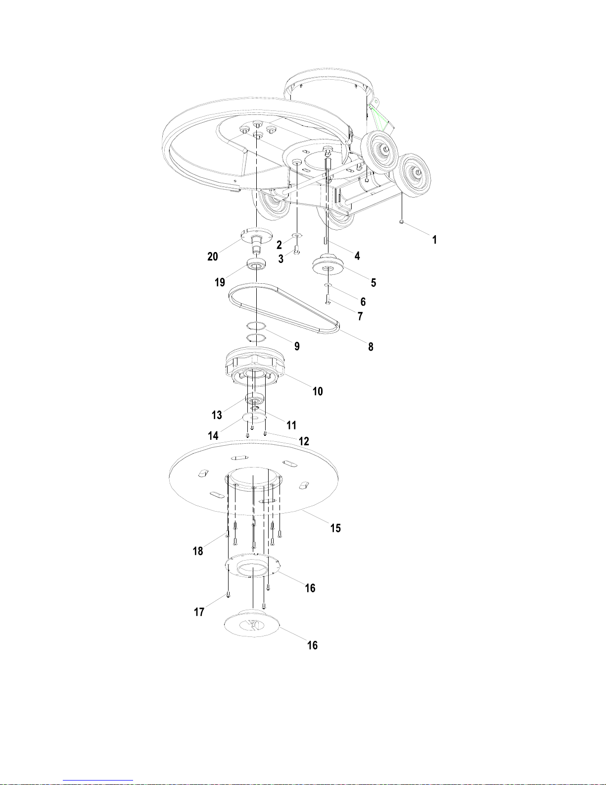
DRIVE/PAD LOCK GROUP
LB1500 86037180 12/29/06
5-5
Page 19
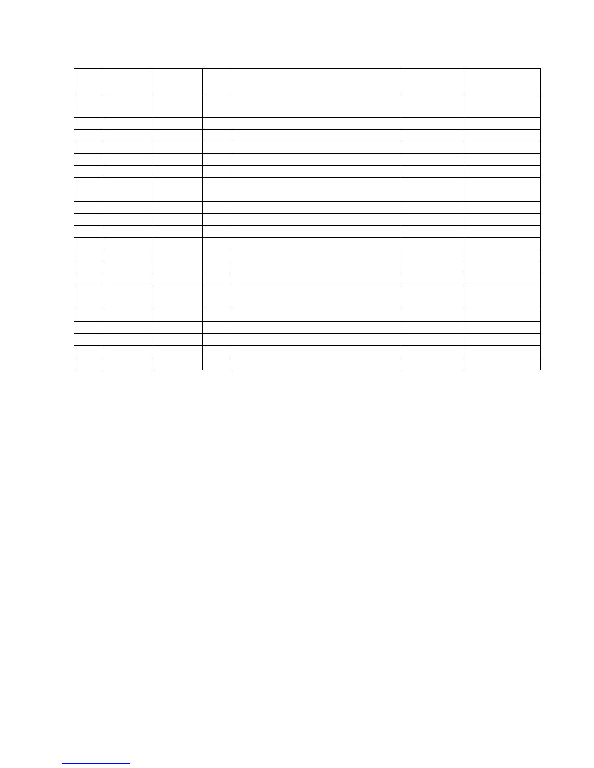
DRIVE/PAD LOCK GROUP
LB1500 86037180 12/29/06
5-
6
REF PART NO. PRV NO. QTY DESCRIPTION
SERIAL NO.
FROM
NOTES:
1 86288740 70709 2
SCR, SET M8 X 1.25 X 8MM CUP
POINT
2 86010720 87086 4
WASHER, M10 X 30 PLTD
3 86006920 70507 4
SCR, 3/8-16 X 3/4 HHCS GR5 PLTD
4 86004820 48041 1
KEY, 3/16 SQ X 7/8 CRS
5 86223280 64106 1
PULLEY, .625 X 3.45
6 86225730 87218 1
WASHER, M6 (20.5OD X 1.6T) PLTD
7 86275570 70505 1
SCR, 1/4-20 X 1.00 HHCS GR5 PLTD
DL
8 86215330 14424 1
BELT, DRIVE 38 IN
9 86223480 67450 2
RING, 52MM INTERNAL SNAP
10 86223290 64107 1
PULLEY, BURNISHER
11 86223470 67449 1
RING, 20MM EXTERNAL SNAP
12 86276730 70719 3
SCR, M4 X 8MM LG PPHMS
13 86223970 09133 1
BEARING, 20MM X 52MM
14 86217510 27913 1
COVER, BEARING
15 86222480 66426 1
PAD DRIVER, 20 IN BURNISHER
FLEX
16 86246740 51353 1
LOCK, PAD DRIVER BLUE
17 86276740 70720 3
SCR, #10 X 3/8 PPHST TYPE B
18 86006670 70201 8
SCR, 1/4-20 X 3/4 FHCS DL
19 86223980 09134 1
BEARING, 25MM X 52MM
20 86214940 03115 1
AXLE, PAD DRIVER
Page 20
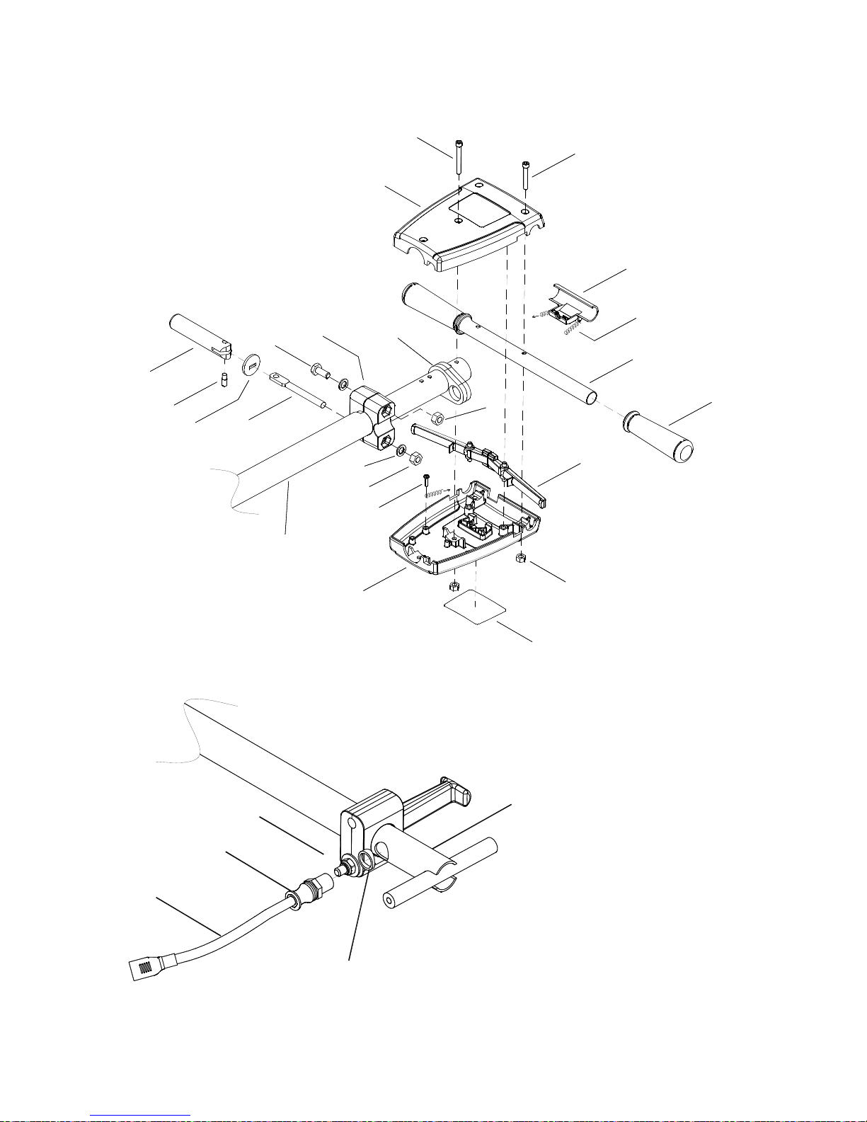
HANDLE GROUP
LB1500 86037180 12/29/06
20
19
13
8
9
7
10
11
12
6
5
4
3
2
1
22
21
18
14
15
16
17
11
27, 11, 12
25
26
24
{
23
5-7
Page 21
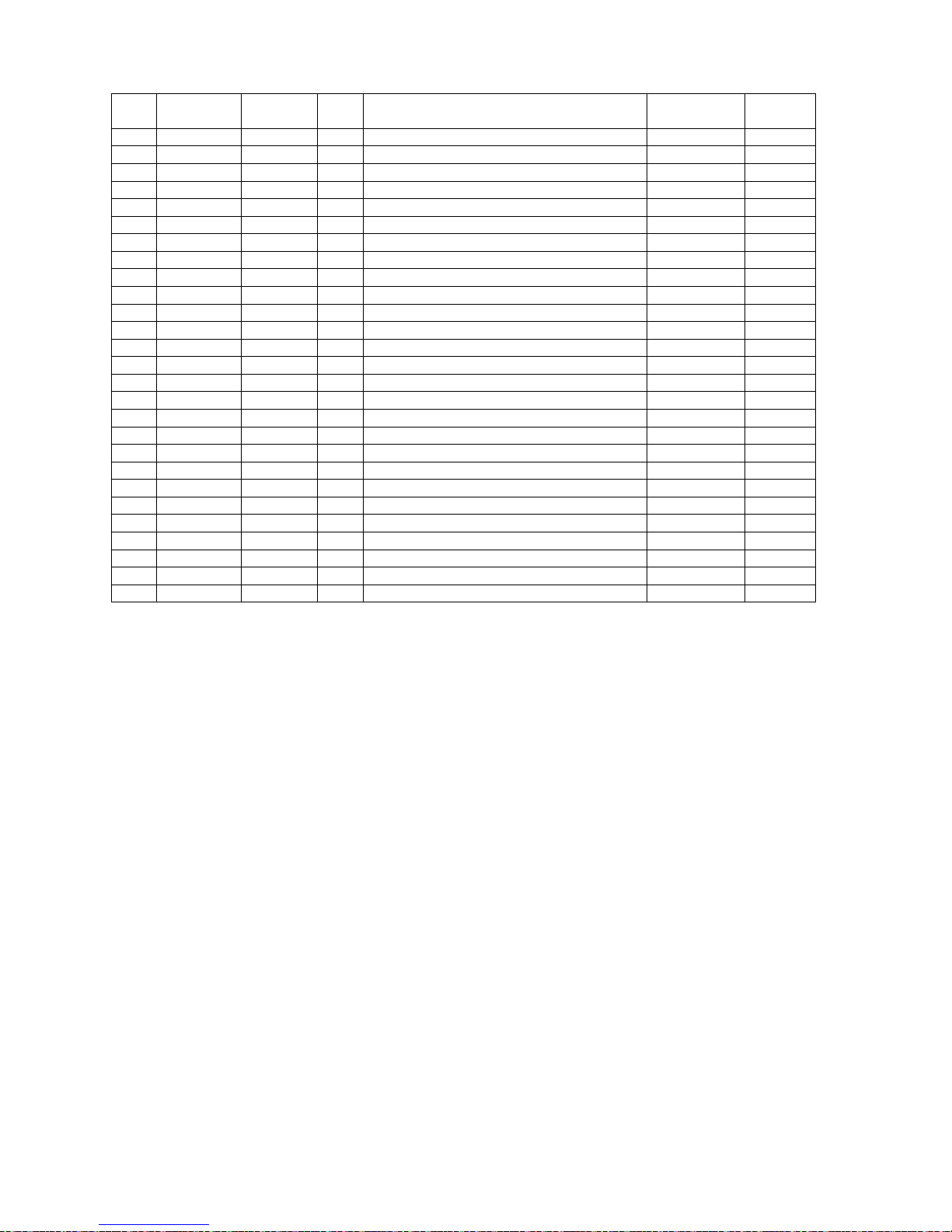
HANDLE GROUP
LB1500 86037180 12/29/06
5-
8
REF PART NO. PRV NO. QTY DESCRIPTION
SERIAL NO.
FROM
NOTES:
1 86136670 70686 2 SCR, M6 X 45 SHCS BLK
2 86005150 51326 1 LOCK, SAFETY HANDLE
3 86224740 73990 2 SPRING, EXT. .5OD X 3.5L
4 86225370 78437 1 TUBE, GRIP HANDLE
5 86004070 36196 2 GRIP, POLISHER HANDLE
6 86005160 51327 2 LEVER, SWITCH
7 86136350 57274 4 NUT, M6 X 1
8 86219740 500194 1 LABEL, WARNING
9 86219320 41363 1 HOUSING, POLISHER HANDLE REAR
10 86288450 70689 2 SCR, M4.8 X 10 HHTF TYPE B
11 86136360 57275 3 NUT, M10 X 1.5 HEX NYLOCK PLTD
12 86010720 87086 3 WASHER, M10 X 30 PLTD
13 86225420 78544 1 TUBE ASM, HANDLE EXTND
14 86223550 67430 1 ROD, HANDLE ADJUSTMENT
15 86225710 87202 1 WASHER, BEARING (HANDLE ADJ)
16 86222560 66334 1 PIN, PIVOT HANDLE ADJUSTMENT
17 86215130 14344 1 BAR, HANDLE ADJUSTMENT
18 86215380 140393 1 BLOCK, HANDLE MOUNT
19 86216370 14434 2 BUMPER, BURNISHER HANDLE
20 86136700 70692 1 SCR, M10 X 75 HHCS PLTD
21 86219330 41366 1 HOUSING, POLISHER HANDLE FRONT
22 86136680 70687 2 SCR, M6 X 50 SHCS BLK
23 86218500 38316 1 HANDLE, BRNSHR EXTND
24 86224300 730021 1 SPACER, POLISHER HANDLE
25 86216920 23206 1 CORDSET, 14/3 X 52” SJT BLK
26 86224930 730012 1 STRAIN RELIEF, 14/3 STRAIGHT
27 86136720 70701 1 SCR, M10 X 1.5 X 90 HHCS PLTD
Page 22
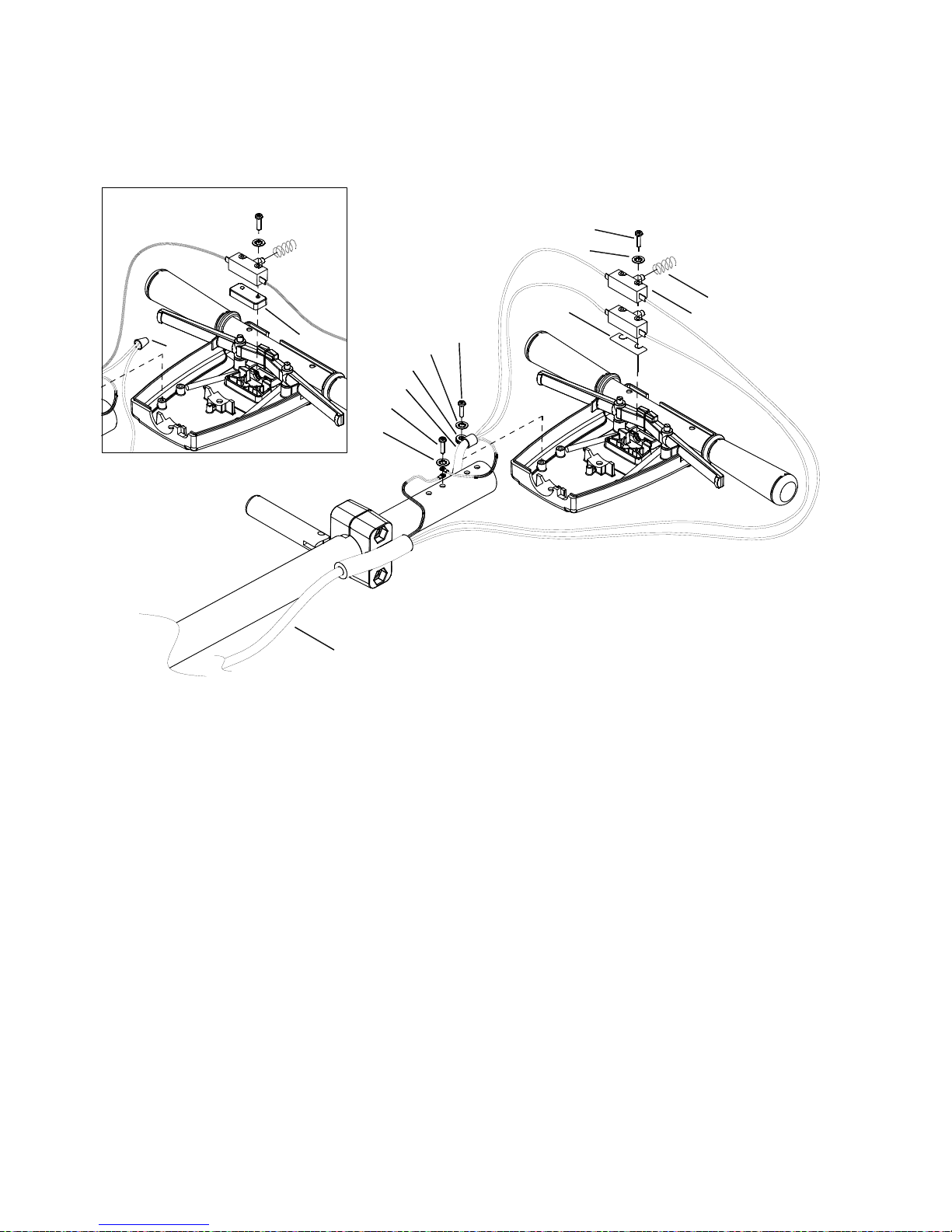
WIRING GROUP
LB1500 86037180 12/29/06
5-9
9
6
8
11
PRIOR TO SN10016973
7
5
10
8
9
12
2
1
3
4
Page 23
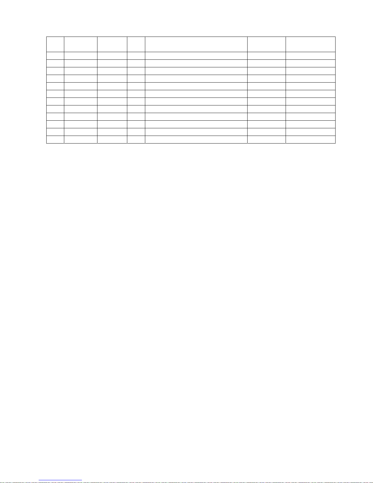
WIRING GROUP
LB1500 86037180 12/29/06
5-1
0
REF PART NO. PRV NO. QTY DESCRIPTION
SERIAL NO.
FROM
NOTES:
1 86136780 70801 2
SCR, M3.5 X 40 PHTF TYPE B
10020019
WAS 70688
2 86137290 87057 2
WASHER, M4 SHAKEPROOF
3 86224750 73993 1
SPRING, COMP, .48OD X .91L
4 86007110 72123 2
SWITCH, 25A SPST 125-250V SNAP
10020019
WAS QTY 1
5 86224550 73989 1
SPACER, SWITCH POLISHER
6 86234150 23167 1
CORD SET, 14/3 STO X 50' YLW
7 86247920 57069 1
NUT, ORG WIRE (2-5 18G/2-14G)
8 86137330 87208 2
WASHER, M5 SHAKEPROOF PLTD
9 86288450 70689 2
SCR, M4.8 X 10 HHTF TYPE B
10 86216920 23206 1
CORDSET, 14/3 X 52", SJT, BLK
11 86198450 20005 1
CLAMP, 5/16 NYLON
12 86215140 140674 1
BARRIER SHEET
10020019
Page 24
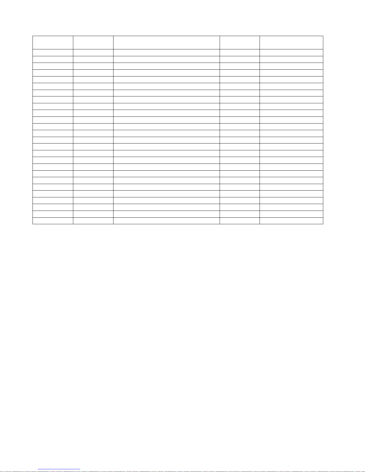
SUGGESTED SPARE PARTS
LB1500 86037180 12/29/06
PART NO. PRV NO. DESCRIPTION
SERIAL NO.
FROM
NOTES:
86225710 87202 WASHER, BEARING (HANDLE ADJ)
86224740 73990 SPRING, EXT .5 OD X 3.5 L
86224750 73993 SPRING, COMP .48 OD X .91L
86007110 72123 SWITCH, 25A SPST 125-250V SNAP
86215130 14344 BAR, HANDLE ADJ
86222560 66334 PIN, PIVOT HANDLE ADJ
86223550 67430 ROD, HANDLE ADJ
86216720 140694 CIRCUIT BREAKER, 25 AMP MP/MB
86223390 67488 RECTIFIER, 50A 600V BRIDGE
86001820 14404 BRUSH SET MOTOR (PKG OF 4)
86003660 34378 FUSE
86003670 34379 FUSE HOLDER
86001020 09135 BEARING, MOTOR
86215460 140397 BRACKET, HANDLE LINK
86226020 89206 WHEEL, 5D X 1.25 X 13MM ID GRY
86225720 87203 WASHER, 14MM ID X 36MM OD
86216600 27871 CAP, EXTRUSION
86216360 14423 BUMPER, EXTURSION 44.30 IN
86222270 57276 NUT, PUSH FLAT RD .51 RD
86223470 67449 RING, 20M EXTERNAL SNAP
86222480 66426 PAD DRIVER, 20IN BURNISHER FLEX
86246740 51353 LOCK, PAD DRIVER BLUE
86223970 09133 BEARING, 20MM X 52MM
86215330 14424 BELT, DRIVE 38 IN
86223980 09134 BEARING, 25MM X 52MM
86217510 27913 COVER, BEARING
5-11
Page 25
(
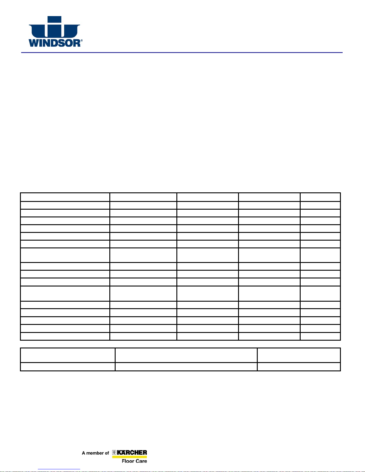
North American New Machine Warranty
Effective on all products shipped AFTER July 31, 2007
WINDSOR INDUSTRIES
Limited Warranty
Windsor Industries warrants new machines against defects in material and workmanship under normal use and service to the original
purchaser. Any statutory implied warranties, including any warranty of merchantability or fitness for a particular purpose, are
expressly limited to the duration of this written warranty. Windsor will not be liable for any other damages, including but not limited
to indirect or special consequential damages arising out of or in connection with the furnishing , performance, use or inability to use
the machine. This remedy shall be the exclusive remedy of the buyer. The warranty period is subject to the conditions stated below.
10 / 3 Warranty: 10 Years Polyethylene (PE) Housings, 3 Years Parts, and Service Labor
Subject to conditions outlined below, Windsor Industries warrants rotationally molded PE housings and parts on all of its machines to
be free from defects in material and workmanship, under normal use and service for ten (10) years to the original owner.
Under this warranty we guarantee the performance of non-polyethylene parts and components to be free from defects for up to three
(3) years or up to 2,500 hours of operation, whichever comes first, to the original end user. Parts replaced or repaired under this
warranty are guaranteed for the remainder of the original warranty period. (See table below)
Service labor charges are covered for up to three (3) years or up to 2,500 hours of operation, whichever comes first, from the date of
purchase through authorized Windsor service provider. No travel coverage is extended for cord-electric models. See table below for
each general product model warranty coverage.
Product PE Housing & Parts Non- PE Parts Service Labor Travel
Rider / Stand up Scrubbers 10 years 3 years or 2000 hours 3 years or 2000 hours 6 Months
Rider Sweepers 10 years 3 years 3 years 6 Months
Walk Behind Scrubbers 10 years 3 years or 2500 hours 3 years or 2500 hours 6 Months
Walk Behind Sweepers 10 years 3 years 3 years 6 Months
Battery Burnishers 10 years 3 years 3 years 6 Months
Extractors / Compass 10 years 3 years 3 years Polishers / Elec. Burnishers /
GH/iCapsol Mini
Wide Areas Vacuums 10 years 3 years 3 years VacPak Vacuums 10 years 1 year 1 year Tracer/Flex Sweepers/Scrubbers 10 years 3 year 3 months 90 days
Air Movers / Dri-matic / TITAN™
/Rombus/Priza
Canister Vacuum 1 year 1 year 1 year Wet/Dry Vacuum 1 year 1 year 1 year Broom 1 year 1 year 1 year Steamer 1 year 1 year 1 year Propane Burnishers / Strippers - 2 year 1 year -
VERSAMATIC® / FLEXAMATIC®
SENSOR®
Product exceptions and Exclusions:
• Extractor brush motors, ALL pump motors, ALL PC boards and electronics, ALL Vacuum motors (other than VERSAMATIC®,
SENSOR® and FLEXAMATIC®), ALL pumps, and diaphragms/Tank bags carry a one (1) year parts and service labor
warranty.
• The Eagle-Robin® engines have three (3) year manufacturer’s warranty. The Honda® and Kawasaki® engines have two (2) year
manufacturer’s warranty. NOTE: The engine warranty is administered through the engine manufacturer and must be repaired at
an authorized service center.
10 years 3 years 3 years -
1 year 1 year 1 year -
Brush motor, Vacuum motor, Belts, Swivel Neck –
3 years
Vacuum motor, Belts – 2 years All other parts/Labor – 1 year
All other parts/Labor – 1 year
Windsor Industries reserves the right to change its warranty policy without notice
Windsor Industries ● ● 1351 W. Stanford Ave. ●
1
303) 762-1800 ● 800-444-7654 ● FAX (303) 865-2794
86019540 PRV NO 98864 Rev8 07/31/07
Page 26

(
North American New Machine Warranty
Effective on all products shipped AFTER July 31, 2007
WINDSOR INDUSTRIES
Normal wear items and accessories including, but not limited to, belts, brushes, FLEXAMATIC® foot pedal, capacitors, carbon
brushes, casters, clutches, cords, filters, finishes, gaskets, hoses, light bulbs, rectifiers, switches, squeegees, bearings, pulleys, relays,
actuating cables, wheels, tires, and propane tanks will be warranted for manufacturing defects for 90-days from the purchase date.
The warranty commences on the purchase date by the original end user from an authorized Windsor agent, subject to proof of
purchase. The Machine Registration Card must be completed and returned immediately at the time of purchase. If proof of purchase
cannot be identified, the warranty start date is 90 days after the date of sale to an authorized Windsor distributor. Parts replaced or
repaired under warranty are guaranteed for the remainder of the original warranty period.
90 Day Warranty Extension Available
Upon receipt of the Machine Registration Card, Windsor will extend by 90 days, from the date of purchase, all items included under
the one-year provision. This applies only to one-year items and does not include 90-day wear items.
This Warranty Shall Not Apply To:
1. Any product that has been subject to abuse, misuse, neglect or unauthorized alteration (including the use of incompatible or
corrosive chemicals or overloading of capacity).
2. Products that have experienced shipping or freight damage.
3. Repairs necessary to correct any failure due to improper pre-delivery service and inspection by the selling dealer.
4. Excessive time for cleaning units in preparation for repair.
5. Any repairs resulting from poor initial service work or improp er diagnosis.
6. Tune-up parts such as plugs, plug wires and condensers.
7. Any design alterations performed by an organization not authorized or specified by Windsor.
8. Battery and charger warranties are handled directly with the manufacturer (Trojan® batteries and Lester® chargers).
9. High-pressure washing.
10. Electrical components exposed to moisture.
If difficulty develops during the warranty period, contact the authorized Windsor agent from whom the product was purchased.
Windsor Industries may elect to require the return of components to validate a claim. Any defective part to be returned must be
shipped freight prepaid to an authorized Windsor Distributor/Service Center or to the Windsor factory.
Use Of Parts Not Approved By Windsor Industries Will Void All Warranties
This warranty is valid only for all products Shipped/Sold AFTER July 31, 2007. A product sold before that date shall be covered by
the limited warranty in effect at the date of sale to the original purchaser.
Windsor Industries reserves the right to change its warranty policy without notice
Windsor Industries ● ● 1351 W. Stanford Ave. ●
2
303) 762-1800 ● 800-444-7654 ● FAX (303) 865-2794
86019540 PRV NO 98864 Rev8 07/31/07
 Loading...