

Lightmed LightLas 532 Operator's Manual
Operator’s Manual
Green Laser Photocoagulator With LCD
LightLas532 – Operators Manual Rev. No 01 Page 1of 115
LightLas 532
Control Panel

Operator’s Manual
for the
LightLas 532
Green Laser Photocoagulator With LCD
Control Panel
Directive 93/42/EEC
as amended by 2007/47/EC
LightLas 532 – Operator's Manual Rev. No 01 Page 2 of 115
Doc. No. : DC1001
Rev. No. : 01

Operator’s Manual for the LightLas 532 Green Laser
Operators Manual for the LightLas 532 Ophthalmic Laser
DC1001
March 2014
Draft prepared
01
August
Release 01 version
Photocoagulator
Clinicians or Doctors should ensure that they are adequately knowledge of the
operation procedures prior to using the LightLas 532 Laser system.
This Operators Manual should be studied and understood before proceeding to
operate the equipment on patients.
CAUTIONS - Use of controls or adjustments or performance of procedures other
than those specified herein may result in hazardous radiation exposure.
CAUTIONS - Any modification to the Ophthalmic Laser will result in the necessity for
it to be reclassified
CAUTIONS - U.S. law restricts this device to sell by or on the order of a physician
This Operators Manual contains confidential and proprietary information of the
Manufacturer.
Manufactured by: LightMed Corporation, No.1-1, Ln. 1, Pao-An St. Sec. 3,Shulin Dist.,
New Taipei City 23861, Taiwan
USA Address: 1030 Calle Cordillera, Suite 101, San Clemente, CA 92673
Tel No.: 949-218-9555 Fax No.: 949-218-9556
Copyright © LightMed Corporation
EU Representative: Medical Device Safety Service GmbH
Schiffgraben 41, 30175 Hannover, Germany
LightLas 532 – Operator's Manual Rev. No 01 Page 3 of 115

Table of Contents
Section 1 INTRODUCTION .................................................................................. 9
Section 2 SAFETY ............................................................................................. 10
2.1 Product Classifications ............................................................... 10
2.2 Warnings and Precautions ......................................................... 11
2.3 Optical Hazards ......................................................................... 12
2.3.1 Nominal Ocular Hazard Distance (NOHD) ........................... 12
2.3.2 Avoid Exposure to Laser beams .......................................... 13
2.4 Electrical Hazards ...................................................................... 13
2.5 Safety Controls and Features ..................................................... 14
2.6 Product Labeling ........................................................................ 14
2.6.1 Console system .................................................................. 14
2.6.2 Integrated Slitlamp LDU .................................................... 16
2.6.3 Laser Indirect Ophthalmoscope LDU ................................... 18
2.6.4 Attachment LDU ................................................................ 19
2.6.5 Safety Filter (Manually) ..................................................... 20
Section 3 PRODUCT SPECIFICATIONS............................................................... 21
3.1 LightLas 532 System Specification ............................................. 21
3.2 CSO SL980 and SL990 Slitlamp Specifications ............................. 24
Section 4 PRINCIPLES OF OPERATION .............................................................. 25
4.1 General Description ................................................................... 25
4.2 LightLas 532 Laser Controls and Displays ................................... 33
4.2.1 Laser Console .................................................................... 33
4.2.2 Slitlamp Delivery Unit ....................................................... 40
4.2.3 Laser Indirect Ophthalmoscope (LIO) ................................. 44
4.2.4 Two types of Integrated CSO SL980 and SL990
Slitlamp Controls Breakdown ............................................ 47
Section 5 INSTALLATION .................................................................................. 51
5.1 Introduction and Requirements ................................................. 51
5.2 Unpacking and Receiving Inspection .......................................... 52
5.3 Tools and Equipment ................................................................. 54
5.4 Setting Up the Laser System Parts .............................................. 55
5.4.1 Slitlamp Integrated LDU .................................................... 56
5.4.2 Laser Indirect Ophthalmoscope LDU (LIO) .......................... 68
5.4.3 Endoprobes LDU ............................................................... 69
5.5 Pre-check / Alignment Procedures ............................................. 72
5.5.1 Pre-check Laser console operation .................................... 72
5.5.2 Pre-check / Alignment LDU ............................................... 74
LightLas 532 – Operator's Manual Rev. No 01 Page 4 of 115

Section 6 CLINICAL USE .................................................................................... 87
6.1 Different types of LDUs Indication / Contraindication Use....88
6.1.1 Slitlamp Delivery Unit ........................................................ 88
6.1.2 Laser Indirect Ophthalmoscope (LIO) .................................. 88
6.1.3 Endoprobe devices ............................................................. 89
6.2 General Warnings ...................................................................... 90
6.3 Possible side-effect or adverse reactions .................................... 92
Section 7 MAINTENANCE ................................................................................. 93
7.1 Operator / User Maintenance ..................................................... 93
7.2 Laser Beam Alignment Check ...................................................... 94
7.3 System Output Power Checking Procedure ................................. 95
Section 8 TROUBLESHOOTING .......................................................................... 97
8.1 Symptom / Warning ................................................................... 97
8.2 Warning ..................................................................................... 99
8.3 Error Codes ............................................................................... 102
Section 9 European Community Issues ............................................................. 106
Section 10 EMC Test Tables ............................................................................... 108
LightLas 532 – Operator's Manual Rev. No 01 Page 5 of 115

LIST OF DRAWINGS / FIGURES
Figure
Description
Page
2.1
Laser Console Safety and Controls Labels
14
2.2
Laser Console Safety labels
15
2.3(a)
Integrated Slitlamp LDU with Labels (RH side)
16
2.3(b)
Integrated Slitlamp LDU with Labels (LH side)
17
2.4
LIO LDU with Labels
18
2.5
Attachment LDU with Labels
19
2.6
Microscope Doctor Safety Filter with Labels
19
2.7
Microscope Safety Filter with labels
20
4.1
System software start up screen shot
29
4.2
System software boot up ok and system is "Standby" mode
29
4.3
System software is ready to shutdown
32
4.4
Laser Console Controls and LCD Displays
33
4.5
LCD Panel Displays and Control
34
4.6
Integrated Slitlamp LDU Controls
40
4.7(a)
Attachment Slitlamp LDU Controls
41
4.7(b)
Truspot Attachment Slitlamp LDU Controls (New version)
41
4.8(a)
Front View of LIO LDU Controls
44
4.8(b)
Top View of LIO LDU Controls
44
4.9
SL980 Slitlamp Parts List and Controls
47/48
4.10
SL990 Slitlamp Parts List and Controls
49/50
5.1
Packing Carton for Integrated LDU and Slitlamp
52
5.2
Portable Carry Cases for Console and LDU’s
53
5.3
Laser System Parts
55
5.4
Slitlamp table top ass'y
57
5.5(a)
Rear view box connection
57
5.5(b)
Removal fuse socket
58
5.5(c)
Removal fuses
58
5.5(d)
Removal voltage setting block and reinsert it back upon completion
59
5.6
Slitlamp Ass’y
59
5.7
Assembled Upper and Lower Housing Screw
60
5.8
Slitlamp mounted onto Table Top ready for Integrated LDU
60
5.9
Slitlamp arm ready for Delivery housing
61
5.10
Fit Delivery unit housing to the Slitlamp
62
5.11
Lock the housing securely to the Slitlamp when it is pushed against
Chrome Stop screw
62
LightLas 532 – Operator's Manual Rev. No 01 Page 6 of 115

Figure
Description
Page
5.12
Align the keyways then fit the Zoom unit to the Delivery housing
63
5.13
Rotate the Zoom housing to the end stop
63
5.14(a)
Original Illumination Tower
64
5.14(b)
New modified Illumination Tower fitted
64
5.15(a)
Haag Streit Attaching Tonometer mount ready for Attachment LDU
65
5.15(b)
Zeiss 30SL Attaching the Tonometer mount and Attachment LDU
Mounting Arm
65
5.15(c1)
Lightmed SYL9000 Attaching Tonometer mount ready for Attachment
LDU
66
5.15(c2)
Lightmed SYL9000 Attaching the Tonometer mount and Attachment
LDU Mounting Arm
66
5.16(a)
Haag Streit Mounting the whole attachment LDU to Tonometer mount
& micromanipulator
67
5.16(b)
Zeiss Style 30SL Mounting the whole attachment LDU to Tonometer
mount & micromanipulator
67
5.16(c)
Lightmed SYL9000 Mounting the whole attachment LDU to Tonometer
mount & micromanipulator
67
5.17
Fiber tips cleaning
68
5.18
LIO connections in console
68
5.19
LIO LDU fiber connection
68
5.20
Endoprobe plug installation
69
5.21(a)
Standard System connection set-up
71
5.21(b)
Combo System Y-Joint connection set-up
71
5.21(c)
Sample of Delivery Fiber and Delivery Key Connection
71
5.22(a)
System boot up sequential display #1
72
5.22(b)
System boot up sequential display #2
72
5.22(c)
Initial Power on displays and outputs
72
5.22(d)
Sample of Delivery Fiber and Delivery Key Connection
72
5.23
Safety filter checks
73
5.24
Attach the Delivery fiber to the Zoom unit
73
5.25
Upper / Lower Slit Alignment Aiming Integrity and Focus Checkout
75
5.26
Realignment set screw location (X-Y axis)
76
LightLas 532 – Operator's Manual Rev. No 01 Page 7 of 115
Figure
Description
Page
5.27(a)
Checking Field of View set-up
76
5.27(b)
Checking manipulator operation on the target
76
5.28(a)
New Type Version Check Slitlamp focus on Target Rod and Laser focus
of aiming beam
79
5.28(b)
Old type Version Adjust the Attachment LDU Spot Size Focus using the
knob on the mounting arm
80
5.29
Old type version Adjusting Micromanipulator Arm to verify Laser Spot is
in the Aperture Center
80
5.30
Old / New type version Adjusting sideways movement of Attachment
LDU during alignment
81
5.31(a)
Fiber and Delivery Key fitted to Console Front Panel
82
5.31(b)
LIO Intensity Control Knob
83
8.1
Sample of Error code display
102
Installation Record Sheet
84/85/86
Power Meter Calibration Record Sheet
96
All the Accessories Listing Detailed
113/114
Record Sheet
Appendix I
LightLas 532 – Operator's Manual Rev. No 01 Page 8 of 115

Section 1 INTRODUCTION
This manual is intended to provide the operator with an overview of the operation
and safety requirements for the LightLas 532 Ophthalmic Laser. This manual is not
intended to provide instructions on actual treatment procedures and it is expected
that users will have undertaken training prior to using the equipment.
The Manufacturer and Distribution organization assume no liability through the use
of this Laser system.
All care has been taken in the preparation and checking of this manual however there
is no guarantee provided that all information is correct. The information provided in
this manual is subject to change without notice.
Only approved or authorized accessories may be used in the LightLas 532. The
Manufacturer and Distribution organization shall not be held liable or responsible for
damages or injury caused as a result of using non-approved accessories. This includes
all Optical Fiber systems, Laser Delivery Units, Safety Filters, Safety Glasses and Table
units.
All maintenance and service work must be carried out by authorized and trained
service agents and only those procedures outlined in the operator and service
manual are allowed. Any service work carried out by unauthorized persons will void
all warranties.
No circuit diagrams or component part lists are to be supplied for the LightLas 532. If
you require technical documentation that is not provided in this manual then please
contact the manufacturer or your local distributor in writing with your reasons for
wanting them and then a copy of the service manual may be provided.
Before using the LightLas 532 Photocoagulator Laser system the operator should
read this manual carefully and pay particular attention to the sections of Safety,
Operation and Maintenance.
LightLas 532 – Operator's Manual Rev. No 01 Page 9 of 115

Section 2 SAFETY
This Laser system has been designed and tested to function in a safe and correct
when used as indicated in this manual.
Do not use this laser before reading and understanding completely this Operators
Manual.
It is important to remember that this laser emits high levels of visible laser radiation
which can cause permanent and irreparable eye and tissue damage. Always observe
precautions for laser safety including using warning signs, safety glasses and only
operating the laser in a treatment room that provides protection to casual observers.
2.1 Product Classifications
The LightLas 532 Photocoagulator Laser is a Class IV laser product as specified in the
standard IEC60825-1 (2007) and the USA 21 CFR’s 1040.10, 1040.11.
The LightLas 532 Photocoagulator Laser is classified as Class I Type B Electromedical
equipment as specified in the IEC60601-1 standard.
The LightLas 532 Photocoagulator Laser is classified as a Class II device according to
the FDA CFR21 regulations.
The LightLas 532 Photocoagulator Laser is classified as a Class II Type B Medical
Device according to the MDD 93/42/EEC (as amended by 2007/47/EC).
The LightLas 532 has been designed to comply with the following standards:
Laser standards
IEC 60825-1 (2007)
USA 21 CFR 1040.10, 1040.11 (1997)
IEC60601-2-22 (1995)
Electrical standards
IEC 60601-1:2005
EN 60601-1:2006
EN 60601-1-2:2007
IEC60601-1-2 :2007
USA UL 2601
JIS T1001 (1992) and T1002 (1992)
Others
MDD 93/42/EEC (as amended by 2007/47/EC)
EN 60601-1-6:2010
IEC 60601-1-6 :2010
LightLas 532 – Operator's Manual Rev. No 01 Page 10 of 115

EN62366 :2008
IEC62366 :2007
EN 980:2008
ISO14971 (2012)
2.2 Warnings and Precautions
The following warnings and precautions apply to the LightLas 532 Laser System and
should be observed by all users at all time:
DO NOT look directly into the laser beam or at laser reflections since direct
and reflected laser light from the laser aperture can cause permanent eye
injury.
DO NOT operate the laser unless observers are using the correct protective
eyewear. The protective eyewear must have an optical density of OD4 or
more at 532 nanometers wavelength. This information must be present on
the eyewear.
DO NOT use objects that can readily reflect light in the vicinity of the laser
beam to avoid reflecting the beam in a hazardous manner.
DO NOT fire the Laser directly onto flammable agents or gasses as the
focused laser beam may cause ignition. There is no AP/ APG protection.
DO NOT try to service or repair the laser other than what is included in this
manual. Service should only be performed by an authorized and trained
agent of the manufacturer.
DO NOT fire the laser on a patient without first checking the operation of the
laser and verifying the optical alignment of the treatment Laser beam.
ALWAYS use the lowest power settings possible when treating a patient
with the laser and start the treatment with minimum level of power.
ALWAYS set the correct spot size and/or use the most appropriate one for
the power setting and type of procedure that is to be performed.
DO NOT put the laser into ‘TREAT’ mode until ready to operate on the
patient.
DO NOT inhale any laser plume generated by the Laser during surgery.
Personnel should take an extreme measured precaution, such as wearing
surgical masks or use plume evacuation systems when a treatment is
undergoing. Caution - Laser plume may contain viable tissue particulates.
ALWAYS take particular care of the optical fibers that connect the Laser
Delivery Units to the Console to make sure they do not get damaged.
LightLas 532 – Operator's Manual Rev. No 01 Page 11 of 115

Additional clinical warnings may be found in Section 6.1.4 of this Manual.
ALWAYS try to let the laser have its own or dedicated power outlet.
Additional items may be plugged in a Multiple Portable Socket Outlet, which
may be plugged into an additional outlet.
DO NOT use the Laser Console if the ambient temperature is outside the
range of 20 to 35°C. This temperature range is the rated operating
temperature limits where the Laser system can be guaranteed to operate
without any interruptions to normal use. Outside this range of temperature
it is possible that the Laser will generate an error condition where the word
“hold” is displayed and the system goes to Standby until the internal
temperature returns to within normal limits then the Laser can be used again
but the error condition may reoccur unless the rated temperature comes
within limits.
2.3 Optical Hazards
Guidance for the safe use of Lasers and Laser systems is found in the standard
IEC60825-1, the USA 21CFR 1040.10, 1040.11 and ANSI Z136.1 - 1986.
During normal operation of the LightLas 532 the operator is protected from Laser
hazards by built in optical absorption Safety Filters. All other personnel in the area
should wear protective eyewear to eliminate the risk of eye injury occurring.
The optical density (OD) of eye protection must be greater than or equal to 4 and the
wavelength 532nm range is also specified on it. It is shown in the following format:
OD4+ @ 532nm
Otherwise, the safety glasses are NOT suitable for this purpose of eye protection.
Safety Glasses are required to have the CE mark applied if used in the EU.
The LightLas 532 uses a Class II Laser Diode Aiming beam. Its wavelength range from
635 to 650 nanometers (nm) and the maximum power output is set at the factory to
be less than 1mW delivered to the patients cornea. However it is always
recommended to use the lowest aiming beam intensity during treatments.
The LightLas 532 Photocoagulator Laser has been classified as a Class 4 and its
classification specified accordingly to the above quoted standards. This classification
is also based on the Accessible Emission Limits (AEL) as calculated according to the
standards.
2.3.1 Nominal Ocular Hazard Distance (NOHD)
The Nominal Ocular Hazard Distance (NOHD) is the distance between the equipment
LightLas 532 – Operator's Manual Rev. No 01 Page 12 of 115

and a person’s eye for which the optical power, from the equipment, entering the
dilated pupil of the person will be less than or equal to the Maximum Permissible
Exposure (MPE) as specified in the standards (i.e. less than a Class 1 Laser Output).
The calculated NOHD for the LightLas 532 with different Laser Delivery Units is:
5 meters at maximum power settings for the Endoprobes
18 meters at maximum power settings and 1000m spot size for Slitlamp Delivery
Units
20 meters at maximum power settings for LIO
Therefore when the laser is in operation, all persons that are closer than these
distances to the equipment should be wearing eye protection.
Patients, where possible, should have the untreated eye covered or protected from
laser reflections.
2.3.2 Avoid Exposure to Laser beams
Reassembly or maintenance of the laser system should only be performed by
authorized and trained personnel. The external housing of the laser system should
never be removed otherwise you or standby observers could be exposed to
dangerous levels of laser radiation and potentially lethal electrical voltages.
Eye safety filters are designed to protect physician’s eyes from back scattered laser
beams must always be used. They are integrated into the Slitlamp and LIO Delivery
Units. When using the endoprobes a separate filter that attaches to the operating
microscope must be used.
For other personnel that may be exposed to reflections or backscatter they must
wear safety glasses or goggles. In any case NEVER look directly at the treatment
laser beam as severe eye injury is likely. This means avoid looking into the aperture of
any of the laser delivery units or the console.
2.4 Electrical Hazards
The Lightlas 532 Photocoagulator laser has been designed to apply the International
Standards for Medical Equipment. The laser system is designed to operate with three
terminal prongs AC voltage where the third prong pin is the earth-grounded prong.
Warning: It is not safe to operate the Lightlas 532 photocoagulator laser without an
earth-grounded receptacle. There is possible risk of electric shock.
No cover or housing need to be removed by the operator or user. Only the
authorized and trained service or agent can remove the cover or housing assembly
LightLas 532 – Operator's Manual Rev. No 01 Page 13 of 115
since there is possible of exposing laser radiation and high current or voltages.
EXPLOSIONSGEFAHR
Dieses Gerat ist nicht fur den Betrieb in
explosiongefahrdeten bereichen bestimmt
exposition dangereuse au rayonnement
Complies to the requirements of
21CFR, Chapter 1, Subchapter J
connect only to with a "Hospital
d'anesthesiques inflammables
Risques d'explosion si utilise en presence
Ne pas ouvrir L'appareil risque de chocs electriques
Laser direct ou diffuse reparations par service
For grounding reliability
Gefahr eines elektrischen Schlages
GEHAUSETEILE NICHT ENTFERNEN
Wartungsarbeiten nur durch qualifizierten
accessible laser radiation. Refer servicing to
Risk of explosion if used in the presence of
Do not remove covers. Shock hazard and
qualified service personnel.
Laserstrahlung zuganglich.
flammable anesthetics.
Kundendienst.
ACHTUNG!
DANGER!
technique qualifie.
Grade receptacle".
DANGER!
FOOTSWITCH
INTERLOCK
DOOR
fuse as marked above
WARNING
Risk of fire
Replace only with
AC MAINS INPUT
50/60Hz, 400VA
100-230V ~ (Fuse:T3.15AH250V)INPUT:
Danger/Caution
DIRECT OR SCATTERED RADIATION
AVOID EYE OR SKIN EXPOSURE TO
Visible and Invisible laser radiation when open
LIO
LIO
LIGHTMED
STOP
Delivery
Key
STOP
DIRECT OR SCATTERED RADIATION
AVOID EYE OR SKIN EXPOSURE TO
Diode Aiming Laser 635-650nm 1mW CW Max
Green Laser 532nm 2.0W CW Max
CLASS 4 LASER PRODUCT
LASER RADIATION
DIRECT OR SCATTERED RADIATION
AVOID EYE OR SKIN EXPOSURE TO
Diode Aiming Laser 635-650nm 1mW CW Max
Green Laser 532nm 2.0W CW Max
CLASS 4 LASER PRODUCT
LASER RADIATION
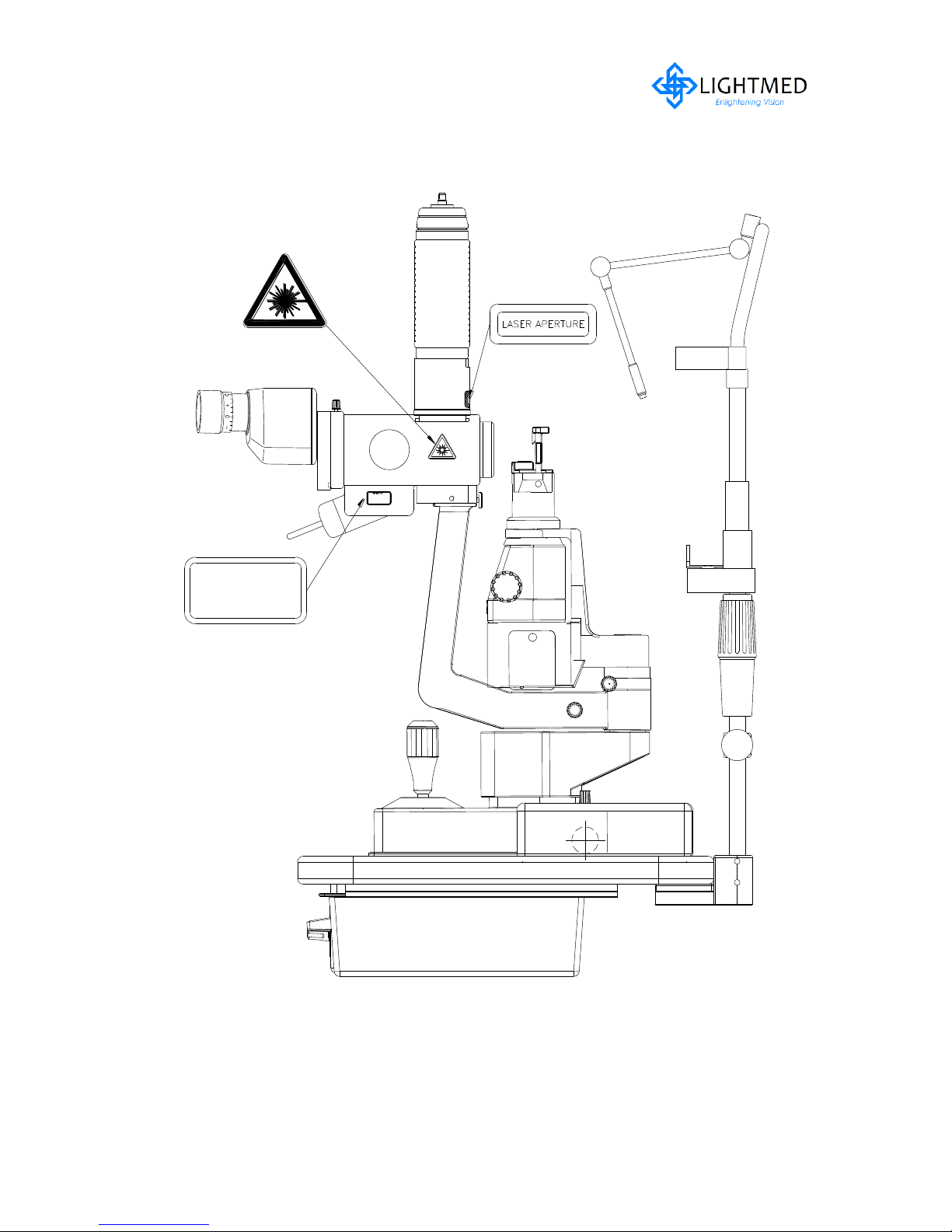
2.5 Product Labeling
All the labels on the LightLas 532 comply with the requirements of the various
regulatory standards referred to previously.
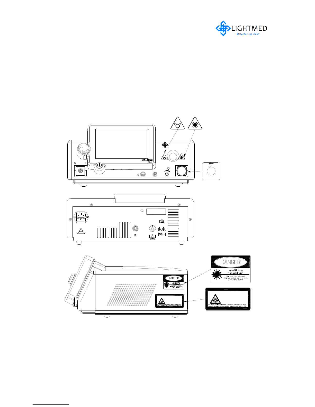
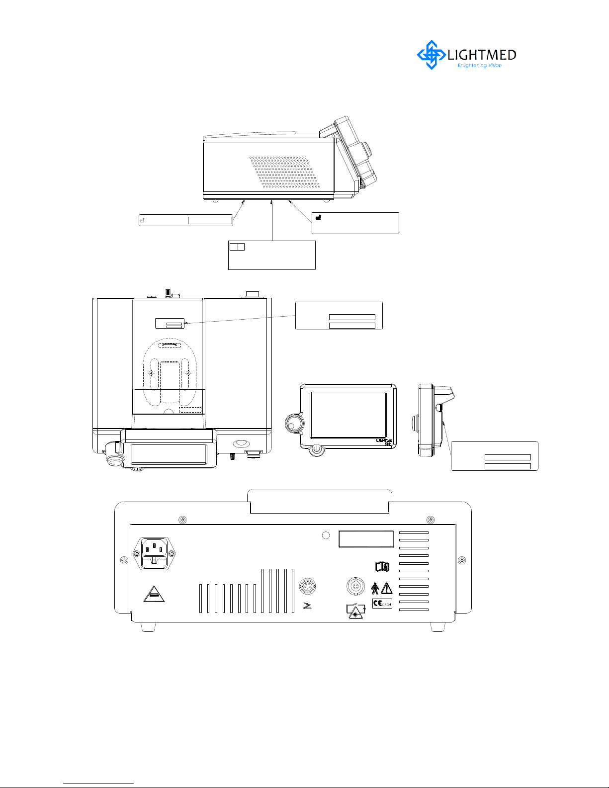
2.5.1 Console system
A full facsimile of all the safety and control labels is shown in the figures 2.1 and 2.2.
Figure 2.1
Laser Console Safety and Control Labels
LightLas 532 – Operator's Manual Rev. No 01 Page 14 of 115
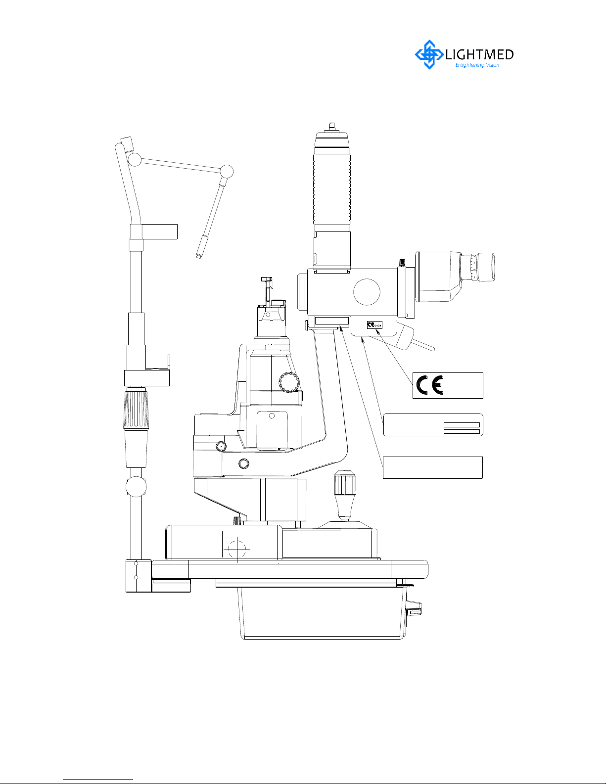
2.5.1 Console system continues...
Lightmed Corporation
SERIAL NO:
MODEL NO:
Lightmed Corporation
SERIAL NO:
MODEL NO:
MANUFACTURED:
Manufactured by LightMed Corporation
No1-1, Lane 1, Pao-An Street, Section 3
Shulin City, Taipei 238, TAIWAN
Schiffgraben 41, 30175 Hannover, Germany
Medical Device Safety Service GmbH
(MDD 93/42/EEC as amended by 2007/47/EC)
EU Authorized Representative
EC REP
"Instructions Under Lid"
Lightmed Corporation
MODEL NO:
SERIAL NO:
Coiling
EXPLOSIONSGEFAHR
Dieses Gerat ist nicht fur den Betrieb in
explosiongefahrdeten bereichen bestimmt
exposition dangereuse au rayonnement
Complies to the requirements of
21CFR, Chapter 1, Subchapter J
connect only to with a "Hospital
d'anesthesiques inflammables
Risques d'explosion si utilise en presence
Ne pas ouvrir L'appareil risque de chocs electriques
Laser direct ou diffuse reparations par service
For grounding reliability
Gefahr eines elektrischen Schlages
GEHAUSETEILE NICHT ENTFERNEN
Wartungsarbeiten nur durch qualifizierten
accessible laser radiation. Refer servicing to
Risk of explosion if used in the presence of
Do not remove covers. Shock hazard and
qualified service personnel.
Laserstrahlung zuganglich.
flammable anesthetics.
Kundendienst.
ACHTUNG!
DANGER!
technique qualifie.
Grade receptacle".
DANGER!
FOOTSWITCH
INTERLOCK
DOOR
fuse as marked above
WARNING
Risk of fire
Replace only with
AC MAINS INPUT
50/60Hz, 400VA
100-230V ~ (Fuse:T3.15AH250V)INPUT:
Danger/Caution
DIRECT OR SCATTERED RADIATION
AVOID EYE OR SKIN EXPOSURE TO
Visible and Invisible laser radiation when open
Figure 2.2
Laser Console Safety Labels
LightLas 532 – Operator's Manual Rev. No 01 Page 15 of 115
2.5.2 Integrated Slitlamp LDU
VISIBLE LASER RADIATION
AVOID EYE OR SKIN EXPOSURE
TO DIRECT OR SCATTERED
RADIATION
CLASS 4 LASER PRODUCT IEC/EN 60825-1:2007
CAUTION/DANGER
VISIBLE LASER RADIATION
AVOID EYE OR SKIN EXPOSURE
TO DIRECT OR SCATTERED
RADIATION
CLASS 4 LASER PRODUCT IEC/EN60825-1: 2007
Figure 2.3(a)
Integrated Slitlamp LDU with labels (RH side)
LightLas 532 – Operator's Manual Rev. No 01 Page 16 of 115
2.5.2 Integrated Slitlamp LDU continues...
AVOID EYE OR SKIN EXPOSURE TO
DIRECT OR SCATTERED RADIATION
0434
Lightmed Corporation
OD4@532nm
Safety Filter
Serial No:
Model No:
Visible laser radiation when open
DANGER / CAUTION
DIRECT OR SCATTERED RADIATION
AVOID EYE OR SKIN EXPOSURE TO
Visible laser radiation when open
DANGER / CAUTION
Figure 2.3(b)
Integrated Slitlamp LDU with labels (LH side)
LightLas 532 – Operator's Manual Rev. No 01 Page 17 of 115
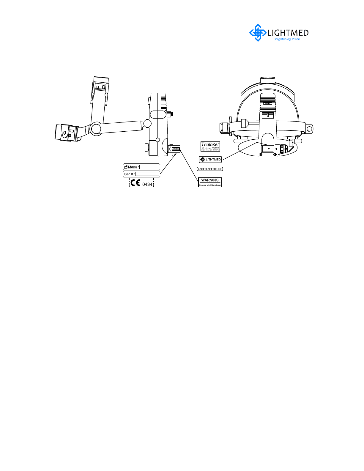
2.5.3 Laser Indirect Ophthalmoscope LDU
Figure 2.4 LIO LDU with labels
LightLas 532 – Operator's Manual Rev. No 01 Page 18 of 115

2.5.4 Attachment LDU
Manufactured:
DANGER / CAUTION
Visible laser radiation when open
AVOID EYE OR SKIN EXPOSURE TO
DIRECT OR SCATTERED RADIATION
CAUTION/DANGER
VISIBLE LASER RADIATION
AVOID EYE OR SKIN EXPOSURE
TO DIRECT OR SCATTERED
RADIATION
CLASS 4 LASER PRODUCT IEC/EN 60825-1:2007
Manufactured:
Lightmed Corporation
Safety Filter OD4@532nm
Model No:
Serial No:
Lightmed Corporation
Serial No:
Safety Filter OD4@532nm
Model No:
400300 500
500
VISIBLE LASER RADIATION
AVOID EYE OR SKIN EXPOSURE
TO DIRECT OR SCATTERED
RADIATION
CLASS 4 LASER PRODUCT IEC825-1(1993)
CAUTION/DANGER
CAUTION/DANGER
VISIBLE LASER RADIATION
AVOID EYE OR SKIN EXPOSURE
TO DIRECT OR SCATTERED
RADIATION
CLASS 4 LASER PRODUCT IEC60825-1 2007
Manufactured:
Serial No:
Model No:
Lightmed Corporation
Safety Filter OD4@532nm
Safety Filter OD4@577nm
Lightmed Corporation
Manufactured:
Serial No:
Model No:
Attachment LDU with labels
Figure 2.6
TruSpot Attachment LDU Labeling
Figure 2.5
LightLas 532 – Operator's Manual Rev. No 01 Page 19 of 115
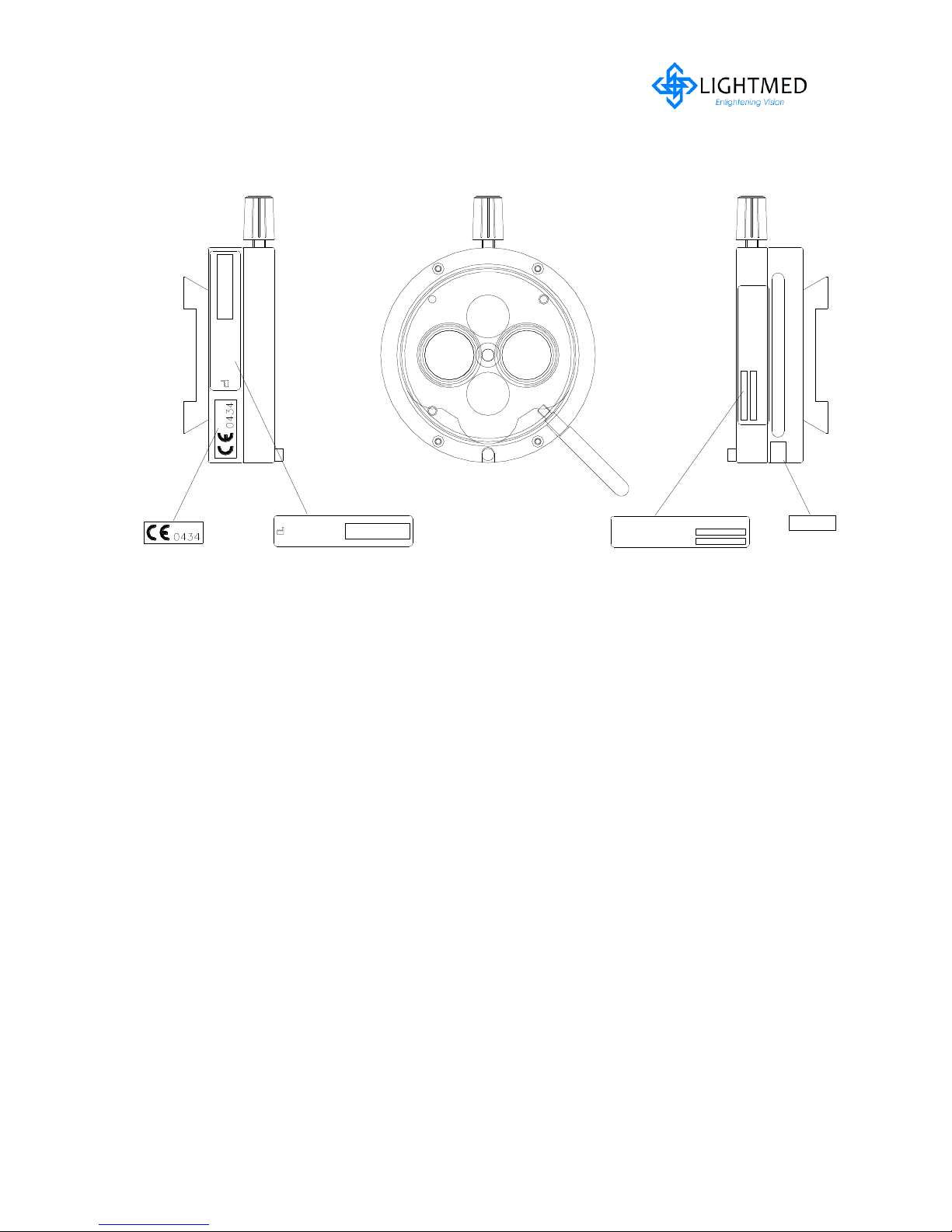
2.5.5 Safety Filter (Manually)
Manufactured:
Manufactured:
OD4@532nm
Safety Filter
Lightmed Corporation
Serial No:
Model No:
FILTER
Lightmed Corporation
Serial No:
Model No:
FIL
OD4@532nm
Safety Filter
Figure 2.7
Microscope Safety Filter with labels
LightLas 532 – Operator's Manual Rev. No 01 Page 20 of 115

Section 3 PRODUCT SPECIFICATIONS
3.1 LightLas 532 System Specification
The following are the System Specifications for the LightLas 532 Ophthalmic Laser.
_____________________________________________________________________
Console Laser System
General Specification
Electrical Input : 100 to 230 Vac. 50/60 Hz Single phase
Power : 400W
Fuse rating : T3.15AH250V @ 100-230Vac (Time Lag)
Temperature Range : Transport: -10 to 70°C
Operating: 15 to 30°C
Storage: -10 to 55°C
Relative Humidity Range : Operating: 30% - 85% non-condensing
Storage and Transport: up to 95% non-condensing
Atmospheric pressure : Operating: 800-1060 mbar
Storage and Transport: 500-1060 mbar
Cooling System : Fan cooled and TEC’s for Laser Diode and Crystal
Dimensions (Total) : 130mm(H) x 370mm(W) x 330mm(D)
Weight : 13 Kg (System) 20 Kg (Packed)
Treatment Laser
Laser Type : Diode Pumped Frequency Doubled YAG
Wavelength : 532 nm
Mode of Operation : CW
Power Output : 2 W Maximum
Power Adjustment : Variable from 0.05 to 2.0 W
Exposure Duration : 0.01, 0.02, 0.03, 0.04, 0.05, 0.06, 0.08, 0.1, 0.15 and
0.2 to 3.0s is 0.1s increment
Repeat Interval : Selectable from 0.01 to 3.0 secs and equal to or greater
than exposure duration in same discrete steps as
duration
SP Mode : Duty cycle selections - 7.5%, 150µs ‘On’ time
- 10%, 200µs ‘On’ time
- 12.5%, 250µs ‘On’ time
- 15%, 300µs ‘On’ time
- 17.5% ,350µs ‘On’ time
- 20%, 400µs ‘On’ time
LightLas 532 – Operator's Manual Rev. No 01 Page 21 of 115

Doctor Safety Filter : OD4 at 532 nm
Safety Class : Class 4
Power Display accuracy: Better than +/-20% of actual
Beam Divergence : < 0.2 NA
____________________________________________________________________
Aiming Laser
Laser Type : Red Laser Diode
Wavelength : 635–650 nm (Red)
Mode of operation : Continuous Wave (CW)
Output power : Maximum of 1.0mW
Power adjustment : Continuously variable
Safety Class : Class 2
___________________________________________________________________
Laser Delivery Units (LDU)
Integrated Slitlamp LDU
Slitlamp model : CSO Model SL980 (Detailed refer to p.32)
Spot Sizes : 50, 100, 200, 300, 400, 500, 1000 m selectable
on Zoom assembly of Delivery unit
Focus plane : All spot sizes Parfocal to Slitlamp focus plane
Fiber Length : 2 m
Mounting : Direct to Slitlamp housing
Safety Filter : Fixed filter OD 4 @ 532nm
Beam Divergence : Cone angle of 20°
Attachment Slitlamp LDU
Slitlamp model : To attach on CSO Model SL990 (Detailed refer to p.32),
Haag Streit models BM or BQ, most Haag Streit Clone
Slitlamps and Zeiss SL30
Spot Sizes : 50, 125, 200, 300, 500m selectable on housing of
Delivery unit
Focus plane : All spot sizes Parfocal to Slitlamp focus plane
Fiber Length : 2 m
Mounting : On adapters fitted to Slitlamp Tonometer Mounts
Safety Filter : Fixed filter OD 4 @ 532nm
Beam Divergence : Cone angle of 20°
___________________________________________________________________
Laser Indirect Ophthalmoscope
Indirect model : Keeler All Pupil II
Retinal Spot size : 300µm nominal at focus with 20D Laser Lens
Illumination power : From Laser Console or stand alone power source
Fiber Length : 3 m
LightLas 532 – Operator's Manual Rev. No 01 Page 22 of 115

Weight : Less than 500g without laser attachment
Safety Filter : Fixed filter OD 4 @ 532nm
Beam Divergence : Cone angle 20°
___________________________________________________________________
Endo-ocular Probes
Probe Types : Straight, Curved and Aspirating
Fiber Length : 3 m
Safety Filters : OD 4 @ 532nm in housing for installation to Operating
Microscope before Laser can be fired
Sterile : Sterilized by Ethylene Oxide and a single use
device only
Beam Divergence : 0.2 NA
___________________________________________________________________
Accessories
Safety Filters
Types : To suit Zeiss, Moeller, Leica and Topcon Operating
Microscopes
Safety Filter : OD4@532nm
LightLas 532 – Operator's Manual Rev. No 01 Page 23 of 115

3.2 CSO SL980 and SL990 Slitlamp Specifications
The following are the Slitlamp Specifications for the CSO SL980 and SL990 Slitlamps
that are used in the LightLas 532 Photocoagulator Laser System. The SL980 is a Zeiss
clone and the SL990 is a Haag Streit clone. Both Slitlamps have very similar
specifications however the SL980 uses an illumination source below the viewing path
and the SL990 uses illumination from above the viewing path.
Microscope : Galilean
Magnification Set : 5 Step Drum Rotation
Eyepiece : 12.5X
Magnification Ratio : 6X, 10X, 16X, 25X, 40X
PD Range : 48.5-80mm
Diopter Adjustment : +/-8
Slit Illumination : 6V 20W Halogen Lamp
Slit Width : 0-14mm (SL980) and 0-12mm (SL990)
Slit Length : 1.8 – 12mm
Slit Apertures : 0.3, 5.5, 9, 14mm(SL980) and 0.2, 1, 3, 5, 9, 12mm(SL990)
Slit Angles : 0°- 180°
Filters : Red Free, Heat Absorbing, Cobalt Blue
Movement Ranges
Longitudinal (In/Out) : 113mm
Lateral (Left/Right) : 108mm
Vertical (Up/Down) : 35mm
Fine movement range : 10mm
Chin Rest Range : 70mm
LightLas 532 – Operator's Manual Rev. No 01 Page 24 of 115

Section 4 PRINCIPLES OF OPERATION
4.1 General Description
The LightLas 532 Green Laser is an Ophthalmic Laser suitable for performing the
following clinical procedures:
Retinal Photocoagulation
Pan Retinal Photocoagulation
Endo photocoagulation
Macular Treatments
Laser Trabeculoplasty
The LightLas 532 Laser system has a wavelength of 532nm, which is in the visible
spectrum and is a green light. A red aiming beam is used to position the treatment
green light beam prior to delivery.
The word LASER is an acronym for “Light Amplification by Stimulated Emission of
Radiation”. The light from a laser has particular characteristics, which makes it a
valuable tool for medical applications.
The beam from a laser is collimated which means that the beam does not
diverge and can maintain a constant diameter over a long distance. This
means that the Laser beam can be focused to a very small spot with high
energy and power densities.
The beam is Monochromatic, which means that it is a single wavelength
beam and therefore the effects of the beam on tissue are very predictable
and reproducible.
The light waves are coherent which means they are in phase with each
other and do not interfere and generate losses in energy.
The LightLas 532 system consists of a laser console where the green laser is housed
along with the electronic control system and power supplies and accompanies along
with various Laser Delivery Units (LDU’s). These LDU’s include:
Slitlamp Integrated into CSO model SL980
Slitlamp Attachment for CSO model SL990 and other Haag Streit clones.
Slitlamp Attachment for Zeiss model SL30 Slitlamp
Laser Indirect Ophthalmoscope (LIO) using a Keeler II
Endo photocoagulation hand pieces (Endoprobes)
When using these LDU’s a microscope Doctor Safety Filter (DSF) is required to
protect the doctor from unexpected reflections causing eye injury during the
treatments. The DSF is mounted in the beam path of the microscope.
LightLas 532 – Operator's Manual Rev. No 01 Page 25 of 115

All the normal functions of a Slitlamp are available to the operator when using the
LightLas 532 on a Slitlamp unit and when the doctor is using the LIO they will use a
Contact Lens of either 20D or 28D.
On the laser console there is a remote control module that the doctor can remove
from the top of the console and position it close to the treatment location so as to
have easy access to the laser displays and controls. This remote control module is
connected to the laser console by a flexible cable that is coiled up and sits in the
recess area on the top of the laser console.
The doctor must first confirm the patient meets the treatment requirements of the
indications and contraindications before proceeding with any treatment. Typically
the doctors or their assistant will verify that the laser and delivery unit are operating
correctly before positioning the patient in the Chinrest are for avoiding any patient
inconvenience. This checking includes the laser output and alignment.
The doctor must set the laser power and pulse interval whenever the System is
turned on. It is the responsibility of the doctor to set acceptable power levels and
pulse intervals. It is recommended that always start with a lower power and shorter
pulse interval to reduce any risk of unintended injury to the patient. By default
setting the laser system, the power is set to 0mW, the pulse duration is set to 0.02
seconds and the pulse interval is set to “One” which means one shot per requested
only. These settings can be altered and saved by the operators or doctors
preference.
Conversely, the doctor can select a repeat pulse mode where the laser is pulsed
repetitively according to the doctor’s requirements. However, even in this mode, the
laser is always under the control of the doctor’s the footswitch, which means that
whenever the footswitch is released, there will be no laser output.
The following paragraphs give a general description of the operation of the Laser
System
The laser system console generates a controlled beam of the 532nm wavelength light
that is focused to a small spot so that it can be delivered into an optical fiber that
then connects to one of the Delivery units. The Slitlamp LDU’s optical fiber has a
diameter of 200µm and is 2 meters long and 3 meters long for the LIO. Special care
must be taken with the fibers not to damage the jacket as this may create extra
losses and may allow the laser beam to be transmitted at the damaged place along
the fiber. Therefore the fiber should be kept off the floor and away from sharp edges.
The 532nm wavelength green laser light is primarily used as a source of energy to
heat the tissue and thereby cause photocoagulation. The laser beam is directly
applied to the treated tissue and absorbed by the melanin pigment within the retinal
pigment epithelium and the choroid. This absorption converts the light energy into
LightLas 532 – Operator's Manual Rev. No 01 Page 26 of 115

heat energy which raises the temperature of the tissue being treated producing
thermal coagulation of the protein. The green laser beam is readily transmitted
through the cornea, lens, and vitreous regions of the eye. If the patient’s eye does
not allow for good transmission or introduces some dispersion of the beam then the
patient is not suitable for this type of laser treatment. Increasing the laser power and
pulse duration will generate more heat and therefore the coagulative effect will be
greater.
If the power or duration of exposure is too high then the surrounding tissue may
sustain some damage. Therefore, a careful selection of the power and pulse
duration is essential to a successful treatment.
Different Types of LDU
For the Slitlamp Delivery Units and LIO, the laser beam is delivered into the patient’s
eye as a focused spot that can be positioned accurately by the doctor to the
treatment site. When using the LIO the laser beam is delivered through a Contact
Lens that is held by the doctor and assists in positioning the laser beam on the site
and setting the desired spot size. For the Slitlamp delivery unit the spot size at the
treatment site is adjustable and set by the doctor according to the type of treatment
to be used. The spot size selector is located on the delivery unit attached to the
Slitlamp and can be set from 50µm to 1000µm in a continuous adjustment for the
Integrated SL980 design. As for Attachment LDU, it can be selected from 50m to
500m.
When using the Endoprobes, the doctor will use an Operating Microscope to view
the patient’s eye. These probes are inserted into the eye and used in very close
proximity to the treatment site (almost in contact). The Endoprobes are sterile
devices intended for direct patient contact and are a purchased item with a sterility
guarantee.
For each LDU, a “Delivery Key” is used by the laser console as a means of
determining which type of LDU is connected. The Delivery Key is required because
each type of LDU has a different amount of loss through the optical elements and
therefore the output power factor calibration will be different for each. The
Endoprobes have the least loss of all the LDU’s because the only losses are through
the fiber itself and in the coupling of the laser beam into the fiber. The LIO has more
loss than the Endoprobes as it has a collimating system, mirror, and focusing lens for
the laser beam to be transmitted through and all of these have some contributing
losses. The least efficient of the LDU’s is the Slitlamp delivery unit. There are many
optics in this unit due to the spot size adjustment zoom system so the losses are the
greatest. Also when the small spot sizes are selected there may be some aperture of
the beam that contributes to the losses.
LightLas 532 – Operator's Manual Rev. No 01 Page 27 of 115

When setting up the laser unit for the operation, the correct type of Laser Delivery
Unit must be connected along with the Delivery Key that accompanies it. If no
Delivery Key is inserted then the warning message “Delivery Key Not Found” on the
LCD screen panel and system will wait for correction or reinserted before normal
console operation resume.
The Delivery Key is also an additional safety feature that prevents unauthorized use
of the laser unit. It is attached to the fiber for each of the LDU’s to eliminate any risk
of inserting the wrong Delivery Key. It is an essential requirement in order to ensure
that the correct calibrated power level is delivered to the patient.
The following paragraphs describe the actual operation of the system
The system consists of two major parts: the console and the LCD touch control panel
integrated with computer platform
Inside the Laser Console there are several operating components that put together
to provide the output Laser beam such as:
Laser Diode (808nm)
Laser Cavity and optics system
Thermal Electric Coolers and Driver units
Electronic Microprocessor control system
Power supply
First of all, main source power must be connected to the laser console system before
the system is enabled to function accordingly. Secondly, a blue LED backlight power
switch, located at the bottom of the screen (refer to fig. 4.3), on the LCD control
panel display needed to be enabled and wait for system software to boot up before
proceed to the next procedure (refer to fig. 4.1 - 4.2). Once the software is properly
boot up, then the key-switch is inserted and turned to the ON position (with the
Emergency switch in the out or OFF position). And then the console system
microprocessor controller will perform some internal checks to verify that the
machine is functioning as it should be. Few warning messages such as, "BBF
Temperature Not Ready", "LBO Temperature Not Ready" ...etc. will display on the
LCD when the console power is ‘ON’. This process usually takes less than few
seconds. If the temperature setting up process time is out of specification (> 5mins),
there will be an error code shown on the LCD display (for more detailed refer to
troubleshooting section of this manual).
LightLas 532 – Operator's Manual Rev. No 01 Page 28 of 115
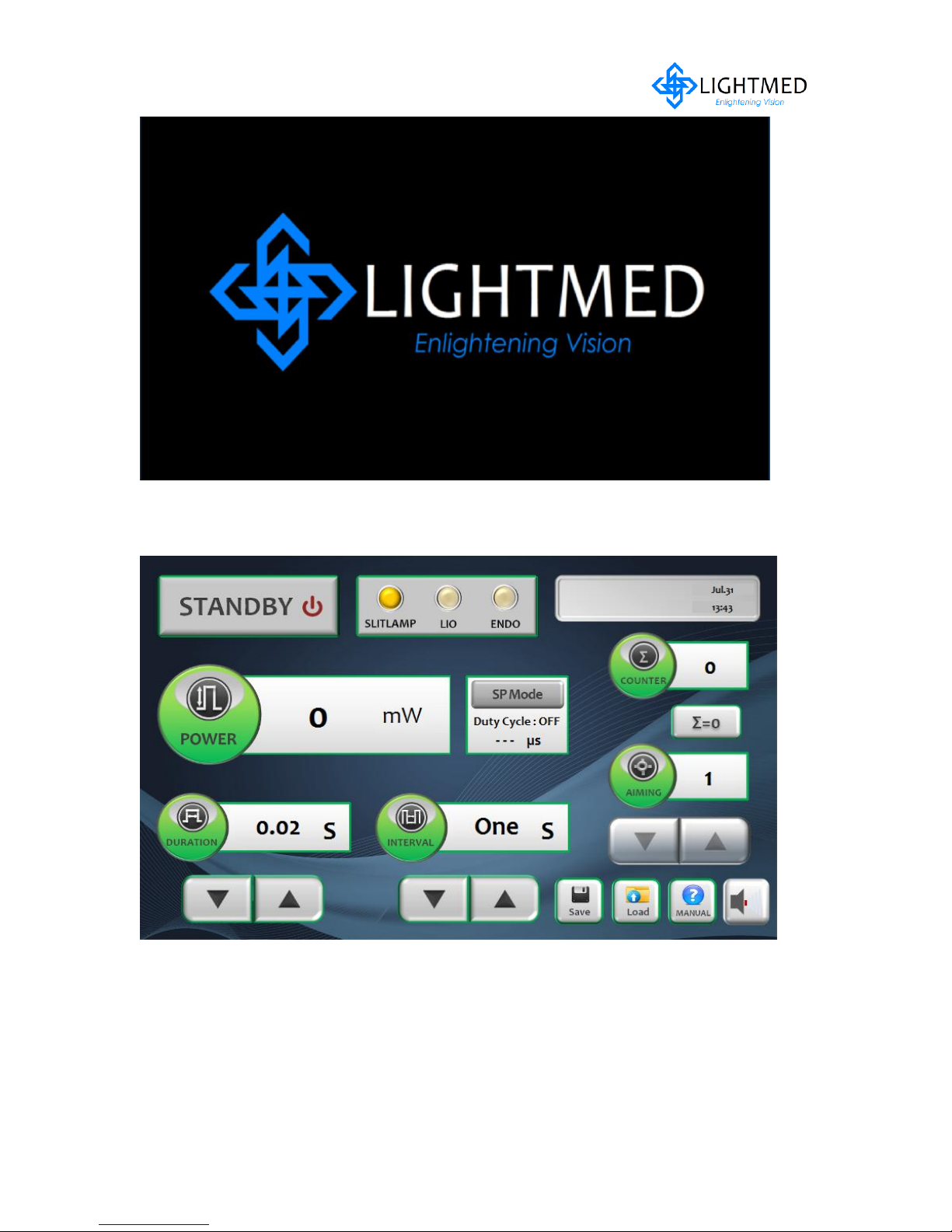
Figure 4.1 System software start up screen shot
Figure 4.2 System software boot up ok and system is "Standby" mode
LightLas 532 – Operator's Manual Rev. No 01 Page 29 of 115

All operating conditions and switches are shown on the LCD control panel. The LCD
control panel display consists of:
Laser Power
Laser Power Pulse Duration
Pulse Interval
Accumulated number of pulses
The type of LDU connected
Aiming intensity
Mode of operation
SP Mode Selection
Customized treatment configuration
Query or Help functionality
The mode of operation is an important function display because when the laser is
turned ON STANDBY mode is automatically selected, which prevents any accidental
firing of the LightLas 532 Laser System with LCD panel. In STANDBY mode, the
footswitch is disabled and the shutter module blocker will obstruct the beam path is
closed.
Only ‘Standby’ button switch is toggled, the system will be in treat mode. Then the
footswitch and shutter are now enabled and the aiming beam is turned on. If the
footswitch is pressed, the Green laser beam will be delivered into the fiber. The
system will turn back to STANDBY mode in the following situations:
No controls are operated for 10 minutes
Any warning or error condition occurs
Prior to activate the ‘Treat’ mode, it is recommended that all operating conditions are
to be set correctly such as patient positioning, power selection, pulses duration,
interval duration, aiming beam intensity, spot size and illumination intensity. This will
prevent the likelihood of accidental firing of the Green laser or unintentional delivery
during the set up stages.
Output power distribution can fine tune through an up/down arrow switch button on
the LCD touch control panel. The power setting will remain the same whenever the
power is on which means the default setting screen will be primary unless it is
replaced by another setting. The power can be adjusted from 50 to 2000 mWatts.
The pulse duration can be adjusted from 0.01 secs to 3.0 secs. by pressing the action
key switch buttons on the LCD touch control panel. Similarly, the Repeat Interval
LightLas 532 – Operator's Manual Rev. No 01 Page 30 of 115
 Loading...