

Lighting Services Inc LP Series, LP1 SuperSPOT Light, LP2 SuperSPOT Light, LP1 LED Installation Instructions Manual
LP SERIES INSTALLATION INSTRUCTIONS
Important
Warning
Purpose
of This
Sheet
Product
Overview
THIS SHEET CONTAINS IMPORTANT SAFETY INSTRUCTIONS. SAVE THESE
INSTRUCTIONS.
This product must be installed in accordance with National Electrical Codes and all other
local codes by a person familiar with the construction and operation of the product and
the hazards involved.
To prevent electrical shock, turn off the power during installation or maintenance.
To reduce the risk of fire, keep away from combustible materials.
The purpose of this sheet is to provide step-by-step instructions to help you:
Install the fixture with any of the following: -00 fitting on an LSI track, -5A canopy, -2G
universal flange fitting, or -3G C-Clamp fitting
Install color/spread gels, glass, hex louver media
Install external accessory cartridge
Install hood and barn door and external accessory cartridge
Replace LED module
Lens cleaning
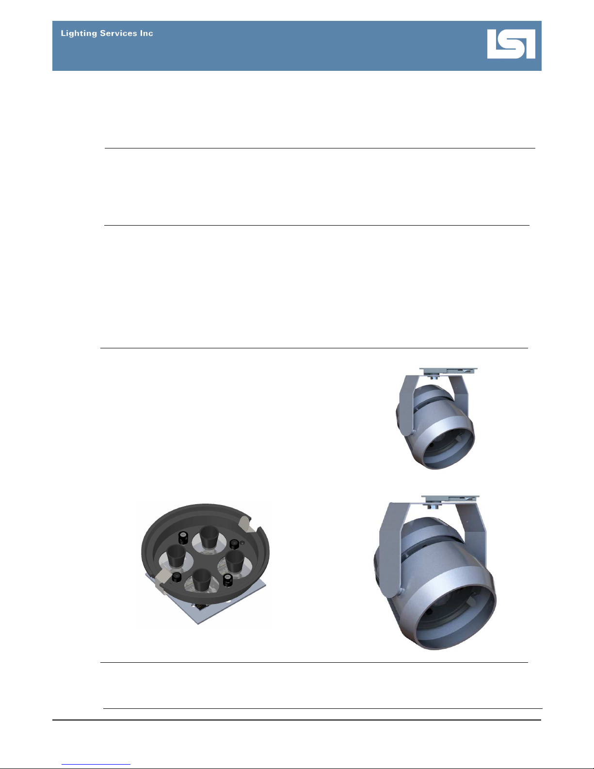
The LP1 and LP2 SuperSPOT lights are high
power, focused, LED spotlights designed
specifically for long throw, tight beam
applications. They are more efficient
alternatives to aging low voltage halogen
sources, such as PAR56 or PAR64.
See the fixture label for voltage and wattage
input.
Please consult our Product Catalog or web
site for available accessories.
LP1 SuperSPOT Light
LP2 SuperSPOT Light
Sample Replacement LED Module
(LP1 LED shown)
Dimming
www.LightingServicesInc.com Page 1 of 9 IS-0213_A 0616
The LP1 and LP2 are fully dimmable using compatible low-voltage electronic dimmers. Other
dimming options are available. Please consult factory.
Please review dimming application guide for more detailed information and a list of compatible
dimmers.
Installing
the Fixture
with the
-00 Fitting
on an LSI
Track
FOR USE WITH LSI 3, 4, 5, 6, 8, AND 9 SERIES TRACK
INSTALLATION INSTRUCTIONS: The track must already
be installed according to code requirements. When installing
or using this track, basic safety precautions should always
be followed, including the following:
Read all instructions.
Do not install any part of a track less than 5 feet above the
floor (8 feet for 277V).
Do not install any fixture closer than 6 inches from any
curtain or similar combustible material.
STEP ACTION
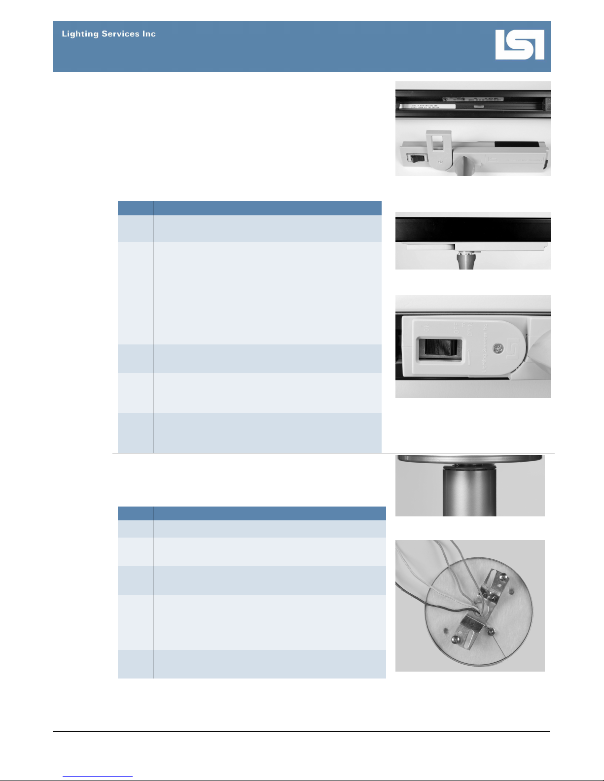
1 Flip the fitting switch off and open the fitting
handle (Fig. 1).
2 Are you using a one-circuit or two-circuit system?
If one-circuit, make sure the brass contacts that
protrude from the side of the fitting face the
copper busbars inside the track.
If two-circuit, inserting the fitting in one direction
connects to circuit one. Removing and
reversing the direction of the fitting connects to
circuit two.
3 Insert the fitting straight up into the track until fully
seated (Fig. 2).
Figure 1. Fitting with switch OFF
and handle OPEN.
Figure 2. Inserted fitting
Installing
the Fixture
with a 5A
Canopy
Close the handle and flip the fitting switch on (Fig
4
3).
WARNING: Do not look directly at lit LED.
5 To remove the fitting, hold the fixture in place, flip
the fitting switch off, open the handle and pull the
fitting straight off the track.
Before Installing: Consult the code requirements for fixture
mounting. Mount the fixture to a ceiling constructed of noncombustible material, away from any flammable materials.
STEP ACTION
1 Turn off all power to the fixture mount.
2 Unscrew the 2 supplied canopy mounting screws,
and remove the crossbar from the canopy (Fig. 4).
Attach the canopy crossbar (Fig. 5) to a ceiling
3
junction box with 2 screws (supplied by others).
Fasten the power wires (Fig. 5) from the junction
4
box to the fixture wires.
Note: Connect green to ground, black to the circuit
line, and white to neutral.
5 Attach the canopy to the ceiling with the 2 supplied
canopy mounting screws.
Figure 3. Switch ON, fitting handle
closed
Figure 4. Fixture mounted on the
5A Canopy
Figure 5. Ground and power wires
with canopy crossbar
www.LightingServicesInc.com Page 2 of 9 IS-0213_A 0616
Installi
ng
the Fixture
Before Installing:
with a -2G
Universal
Flange
Fitting and
a -3G
C-Clamp
Fitting
Consult the code requirements for fixture
mounting, and check the distance-from-wall label inside the
fixture. Mount away from any flammable materials.
For the -2G fitting, follow steps 1, 2, 4, and 5.
For the -3G fitting, follow steps 1, 3, 4, and 5.
STEP ACTION
1 Turn off all power to the fixture.
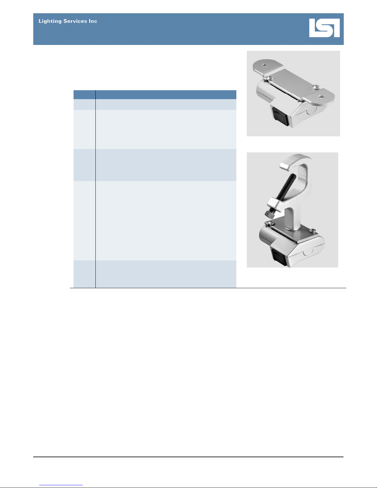
Attach the -2G fitting (Fig. 6) to any non-
2
combustible material, using the 2-hole flanged
mounting plate with 2 screws (supplied by
others) or bolt-up applications, such as Unistrut
or Kindorf systems.
Attach the -3G fitting (Fig. 7) to a non-
3
combustible pipe measuring 5/8” to 2” in outside
diameter, and then secure the fitting by turning
the C-clamp bolt clockwise.
4 Plug the fixture into a power source.
IMPORTANT SAFETY INSTRUCTIONS
This product has a polarized plug (one blade is
wider than the other) as a feature to reduce the
risk of electric shock. This plug will fit in a
polarized outlet only one way. If the plug does
not fit fully in the outlet, reverse the plug. If it still
does not fit, contact a qualified electrician. Never
use with an extension cord unless the plug can
be fully inserted. Do not alter the plug.
Figure 6. -2G universal flange fitting
5 Turn on the main power, and then flip the fitting
switch on.
Note: The switch is located on the base of fitting.
Figure 7. -3G C-clamp fitting
www.LightingServicesInc.com Page 3 of 9 IS-0213_A 0616
 Loading...