

Page 1

®
™
THE BLUE BOX
LT
OPERATION
& MAINTENANCE
MANUAL
LCDBBO&M03Sept08
®
Lighting Control & Design
905 Allen Ave, Glendale CA 91201
Tel: 800-345-4448 • www.lightingcontrols.com
Page 2

Page 3

THE BLUE BOX LT OPERATION & MAINTENANCE MANUAL 3
TABLE OF CONTENTS
OVERVIEW..........................................................................5
GR1404LT / GR1408LT Drawings & Details......................................................7
Relay Overview ..........................................................................10
GR1416 LT Drawings & Details.................................................................11
Introduction to The Blue Box LT™ Series......................................................15
The Blue Box LT™ vs. Lighting Contactors .....................................................16
Build Your System in 3 Steps ................................................................17
Most Popular Accessories ..................................................................20
Applications...........................................................................22-23
MAINTENANCE & TROUBLESHOOTING ..............................................25
Making Up Cat. 5 Cable With RJ45 Connectors ................................................27
How To Make Proper Crimps...............................................................35
Adding a New Device ..........................................................................39
Parts Replacement & Installation Guide...............................................47
Hardware Troubleshooting .........................................................59
Troubleshooting with An Oscilloscope................................................63
Programming ....................................................................67
DTC Clock Navigation Basics ...............................................................69
Manual Control of Relays ..................................................................70
Programming Switches or DI Inputs..........................................................71
Time Schedules...........................................................................73
Programming a Blue Box LT Photocell........................................................76
To Add a Holiday List to a Schedule .........................................................77
More Data on Scheduled Events ............................................................78
Group Types .............................................................................80
Programming Groups......................................................................81
Additional Groups Parameters ..............................................................82
Group FAQs .............................................................................83
Other System / Set up Programming.........................................................86
LCDBBO&M04Sept08
Daylight Saving Time .......................................................................86
Keyboard Lock Code ......................................................................87
Page 4

4 THE BLUE BOX LT OPERATION & MAINTENANCE MANUAL
TABLE OF CONTENTS (Continued)
Time Schedule Programming Examples...........................................................88
Exercise #1- Contact Closure Device Controlling 4 Relays ......................................88
Exercise #2 - Contact Closure Device Controlling 10 Relays ....................................88
Exercise #3 - Time Schedules with Override Switches ..........................................88
Exercise #4 - Retail Store ..................................................................89
System Diagnostics Tools...........................................................91
System Start Up & Cabling Guide ...................................................95
Frequently Asked Questions .......................................................103
APPENDIX ........................................................................111
Installation Guide GR1404 LT & GR1408 LT ..........................................113
Installation Guide GR1416 ........................................................117
Chelsea Installation Guide ........................................................121
PCO Installation (Out Door Photocell) Installation Guide ..............................123
Digital Input Card Installation Guide (For Contact Closures)............................125
Occupant Sensors (Hook-Up and Programming)......................................129
Novitas® Brand Occupant Sensors .............................................................131
Sensor Switch® Brand Occupant Sensors ........................................................132
Wattstopper® Brand Occupant Sensors .........................................................133
Hubbell® Brand Occupant Sensors .............................................................134
LC&D® Brand Occupant Sensors...............................................................135
Clock /Programming Navigation Tree ...........................................137-139
Technical Glossary ...........................................................141-143
LCDBBO&M04Sept08
Page 5

®
™
THE BLUE BOX
OVERVIEW
LT
LCDBBO03Sept08
®
Lighting Control & Design
905 Allen Ave, Glendale CA 91201
Tel: 800-345-4448 • www.lightingcontrols.com
Page 6

6 THE BLUE BOX LT OVERVIEW
TABLE OF CONTENTS
GR1404LT / GR1408LT Drawings & Details..........................................................7
Relay Overview ..................................................................................10
GR1416LT Drawings & Details .....................................................................11
Introduction to The Blue Box™ LT Series ...........................................................15
The Blue Box™ LT VS. Lighting Contactors .........................................................16
Build Your System In 3 Steps .......................................................................17
3 Enclosure Sizes ..................................................................................18
2 Panel Configurations.............................................................................19
Master Relay Panel ................................................................................19
Slave Relay Panel..................................................................................19
Most Popular Accessories . . . . . . . . . . . . . . . . . . . . . . . . . . . . . . . . . . . . . . . . . . . . . . . . . . . . . . . . . . . . . . . . . . . . . . . . . . 20
Applications .......................................................................................22
Small Parking Lot (Single Control Panel) ..............................................................22
Retail Stores (With 6 Override Zones)...............................................................22
Warehouse (Multiple Control Panels)................................................................23
Blue Box Technical Support ........................................................................24
LCDBBO03Sept08
Page 7
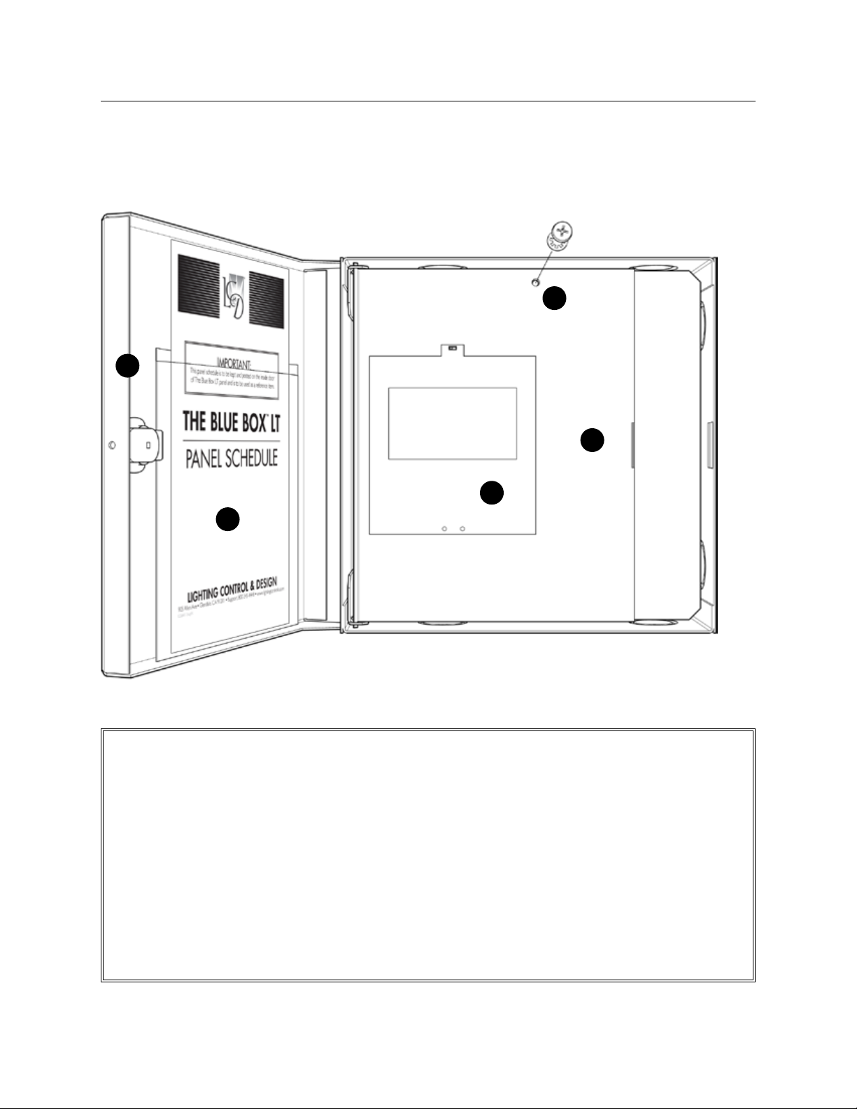
THE BLUE BOX LT OVERVIEW 7
GR1404LT / GR1408LT DRAWINGS & DETAILS
1
3
2
4
LCDBBO03Sept08
5
NEMA 1 surface mount enclosure with hinged door and key lock;
8.375” h x 8.375” w x 3.125” d (GR1404 LT)•
13.5” h x 8.5” w x 3.125” d (GR1408 LT)•
GR1404/08 LT (FRONT DOOR OPEN)
Screw fastener secures white door (Master only).1.
White door provides a barrier between Control 2.
Interface and High Voltage connections beneath
(Master only).
Hinged locking blue door.3.
DTC Clock / Display & Programming Interface: 4.
32-channel, 365-day astronomical clock with
Scroll and Tab to access control features for entire system (Master only).
Door pocket contains the following documenta-5.
tion: Refer to the Blue Box LT Installation Guide
for more information on these documents.
Panel Schedulea)
(optional) DI Card schedule.b)
If this is a Master panel, the System Device c)
Schedule on the back of the Panel Schedule
should also be filled-out.. It lists out all of the
digital lighting controls devices, where they are
and what they do. (see System Star t-Up Guide
for more information.
Page 8
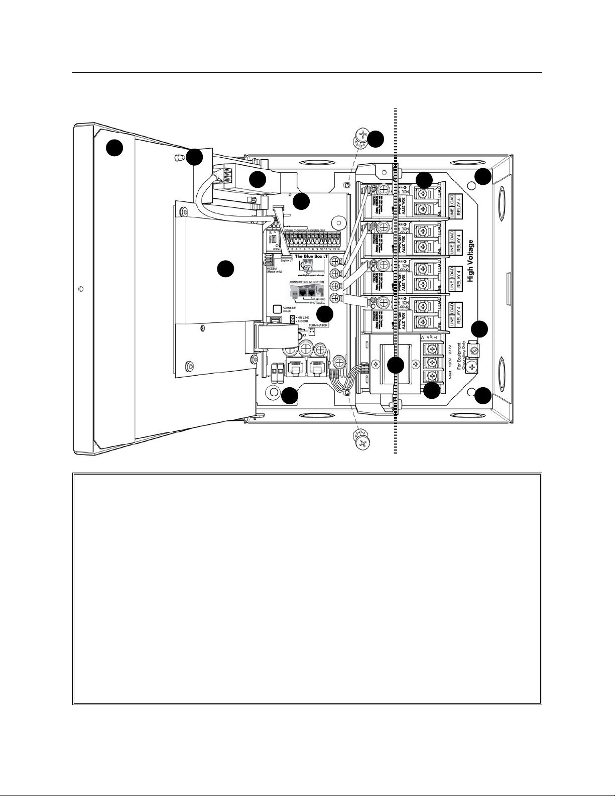
8 THE BLUE BOX LT OVERVIEW
low voltage only line voltage only
2
1
8
3
4
12
6
9
7
10
5
11
55
GR1404/08 LT (WHITE DOOR OPEN)
Screw fastener secures hinged Control Panel 1.
Door (Master only).
White door provides barrier between human 2.
interface and line voltage connections beneath
(Master only).
Optional Modem. Free factory dial-up programming.3.
Optional DI contact closure interface card.4.
Ø1/4" mounting holes at 4 places.5.
Optional: Unfasten two screws to remove chassis 6.
assembly from enclosure providing full access to
mounting holes if required.
SnapLink7.
LED is ON when relay is OFF.
DTC Clock / Display & Programming Interface: 8.
™
relays, Normally-Closed (NC). Status
32-channel, 365-day astronomical clock with
Scroll and Tab to access control features for entire system (Master only).
Voltage barrier separates line voltage (class 1) & 9.
low (class 2) connections.
Dual Voltage Power Supply Input: Blue Box LT10.
operates on either 120V or 277V.
Ground Lug for equipment grounding.11.
Relay Control Card provides interface between 12.
control network and relays. The Relay Control
Card in the Master panel also holds time schedules and system mapping.
™
LCDBBO03Sept08
Page 9
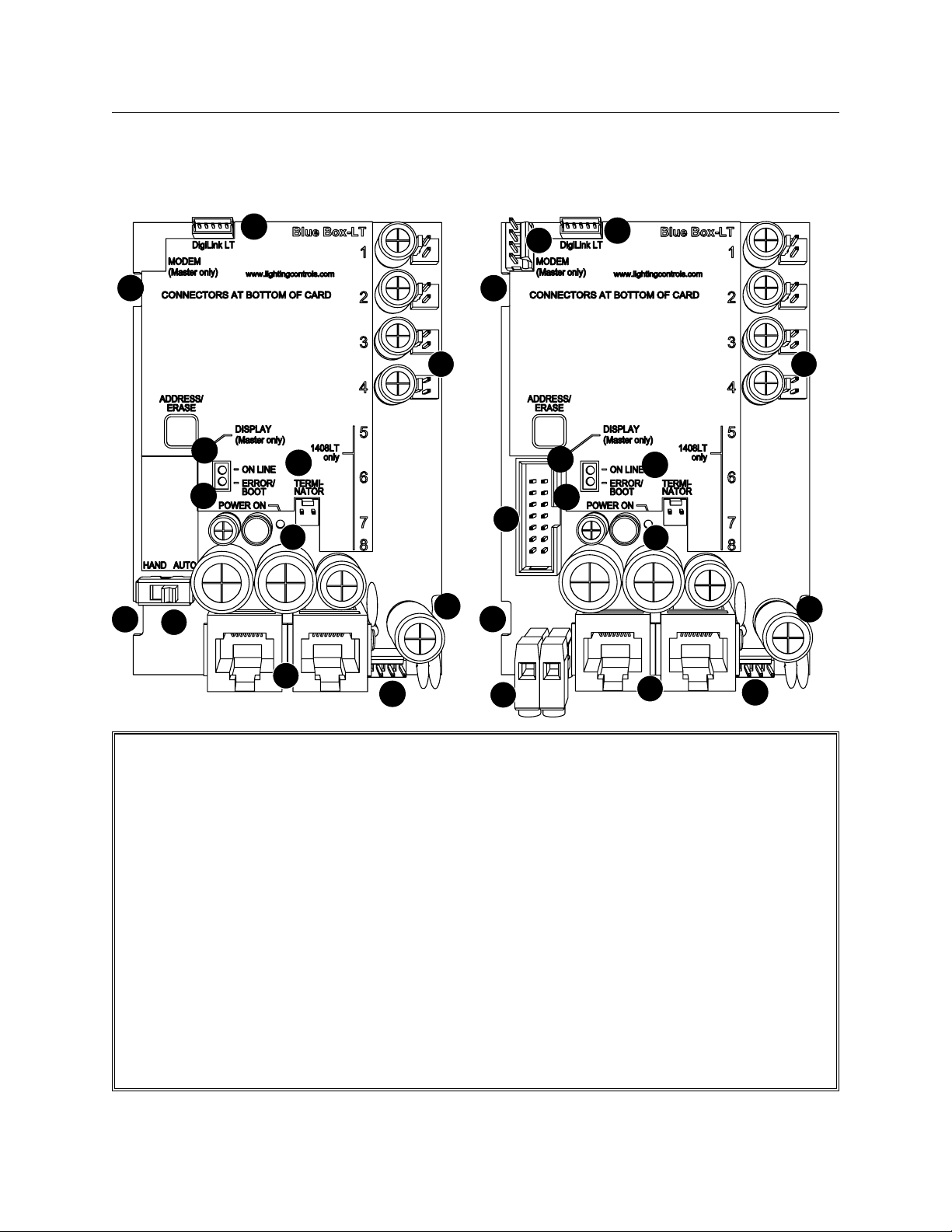
THE BLUE BOX LT OVERVIEW 9
GR1404/08 SLAvE PANEL RELAY CONTROL CARD
4
7
1
9
11
8
10
7
7
12
GR1404/08 MASTER PANEL RELAY CONTROL CARD
5
4
7
1
9
11
8
6
10
7
7
LCDBBO03Sept08
2
13
Relay Drivers. Opto-isolated to prevent line volt-1.
age back-feed and to help prevent RF and EMF
noise interference. Relay drivers will close latching
relays upon loss of power to the Control Card.
RJ45 sockets for digital bus. Digital devices (relay 2.
panels, digital switches, etc) connect to this panel
using a bus (daisy-chain) topology.
Photocell port (master panel only). +V output 3.
with a photocell input. Photocells are polarized follow color code.
Power/data connector for DI Card.4.
Power/data connector for modem (master panel).5.
Power/data connector for DTC clock/display 6.
(master panel only).
Removal slots for control card. Used with a flat 7.
blade screw driver to remove the Control Card.
3
Terminator pins. Add terminator here if this is the 8.
first or last item on a bus (follow the “System
Start-Up & Cabling Guide”).
Online LED indicates the communications mi-9.
cro-processor is functioning, not that the panel
can see the digital bus.
Power ON LED indicates the control card is re-10.
ceiving power from the transformer and has successfully converted it to DC.
Error/Boot LED. Flashes continuously if system 11.
failed to boot.
Hand/Auto Switch (slave panel only). In Auto 12.
mode, relays will react to schedules and switches.
In Hand mode, relays will remain closed.
Power input from transformer.13.
2
13
Page 10
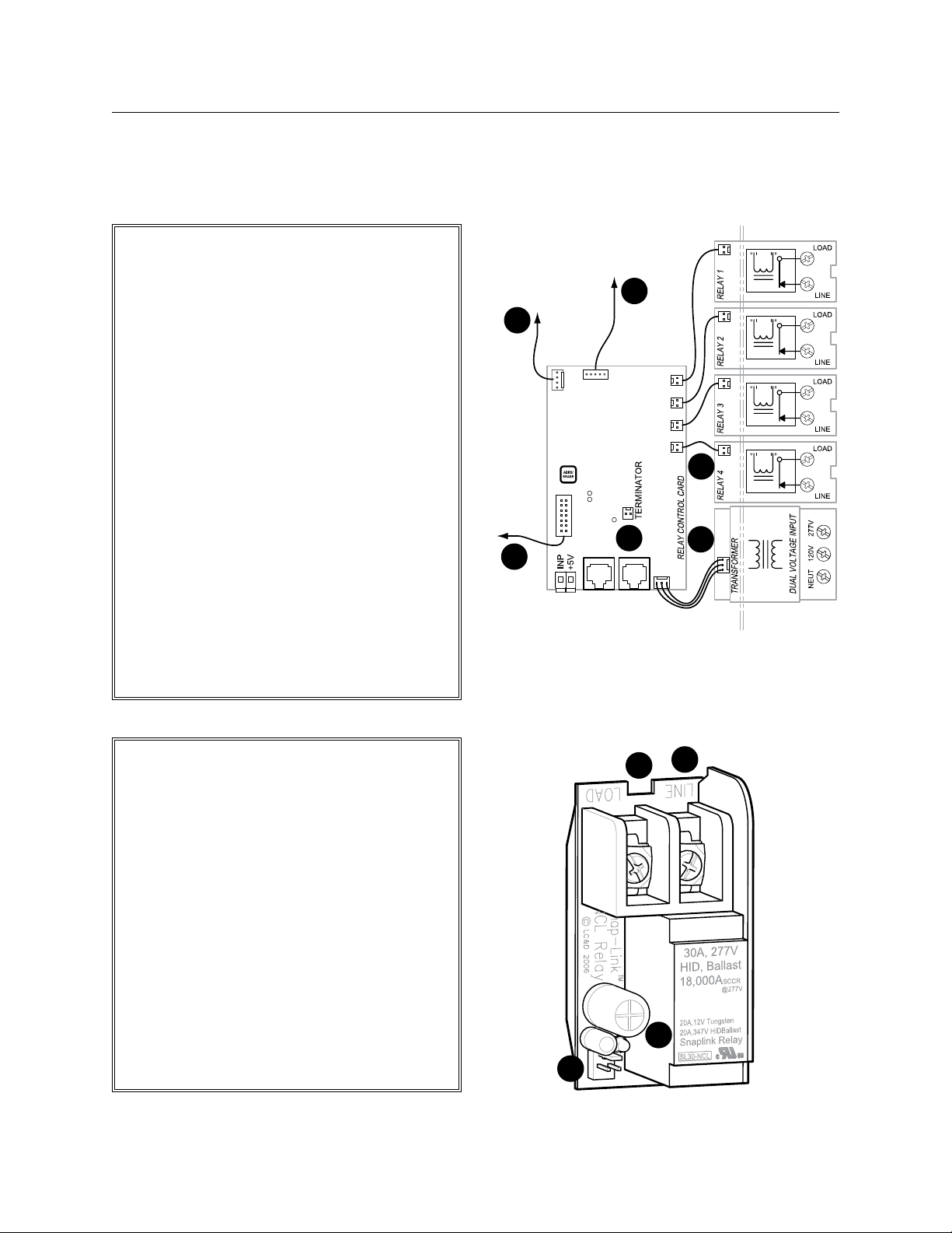
10 THE BLUE BOX LT OVERVIEW
BLUE BOX LT 1404/1408
INTERNAL SCHEMATIC
3#18 AWG. Supplies power from trans-1.
former to relay control card.
14 conductor ribbon cable: carries control 2.
signal between DTC and relay control card
(master panel only).
2 conductor ribbon cable: carries control 3.
signal from smacker strip to relays - one
per relay.
5 conductor ribbon cable: carries digital 4.
signal from relay control card to (optional)
digital input card.
4#22AWG carries RS-232 signal from 5.
(optional) modem to relay control card
(master panel only).
Terminator pins. Add terminator here if this 6.
is the first or last item on a bus (follow the
“System Start-Up & Cabling Guide”).
For more information about external hook-ups,
refer to GR 1404 LT Installation Guide.
To optional
Modem
master panels
only
5
To DTC
2
To optional
DI Card
4
6
3
1
RELAY OvERvIEW
Low voltage connector.1.
Status indicator LED.2.
Quick removal slot.3.
High conductivity terminal block.4.
SnapLink
ing (NCL), UL listed for 30 amps lighting (ballast,
HID) at 277v, 20 amps at 347v and 20 amps
Tungsten at 120v, 18,000 amp SCCR at 277v,
rated 250,000 on/off cycles, 3 yr. warranty.
™
Latching Relay: Normally closed latch-
1
3
4
2
LCDBBO03Sept08
Page 11
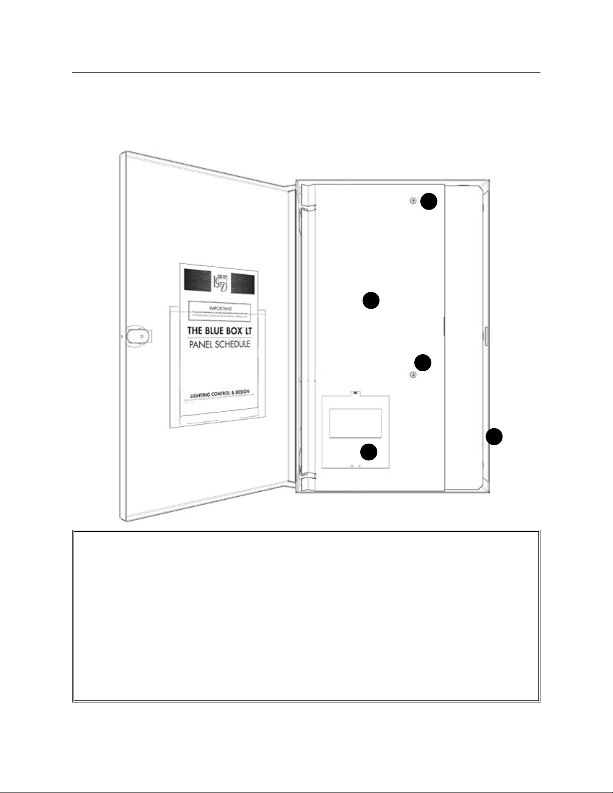
THE BLUE BOX LT OVERVIEW 11
GR1416LT DRAWINGS & DETAILS
1
2
LCDBBO03Sept08
1
3
4
GR1416 LT (FRONT DOOR OPEN)
Screw fastener secures hinged Control Panel Door (Master only).1.
Hinged Door Panel provides a barrier between Control Interface and High Voltage connections beneath 2.
(Master only).
NEMA 1 surface mount enclosure with hinged door and key lock; Ø1/4" mounting holes at 4 places 3.
(hardware not included).
DTC Clock / Display & Programming Interface: 32-channel, 365-day astronomical clock with Scroll and Tab 4.
to access control features for entire system (Master only).
Page 12
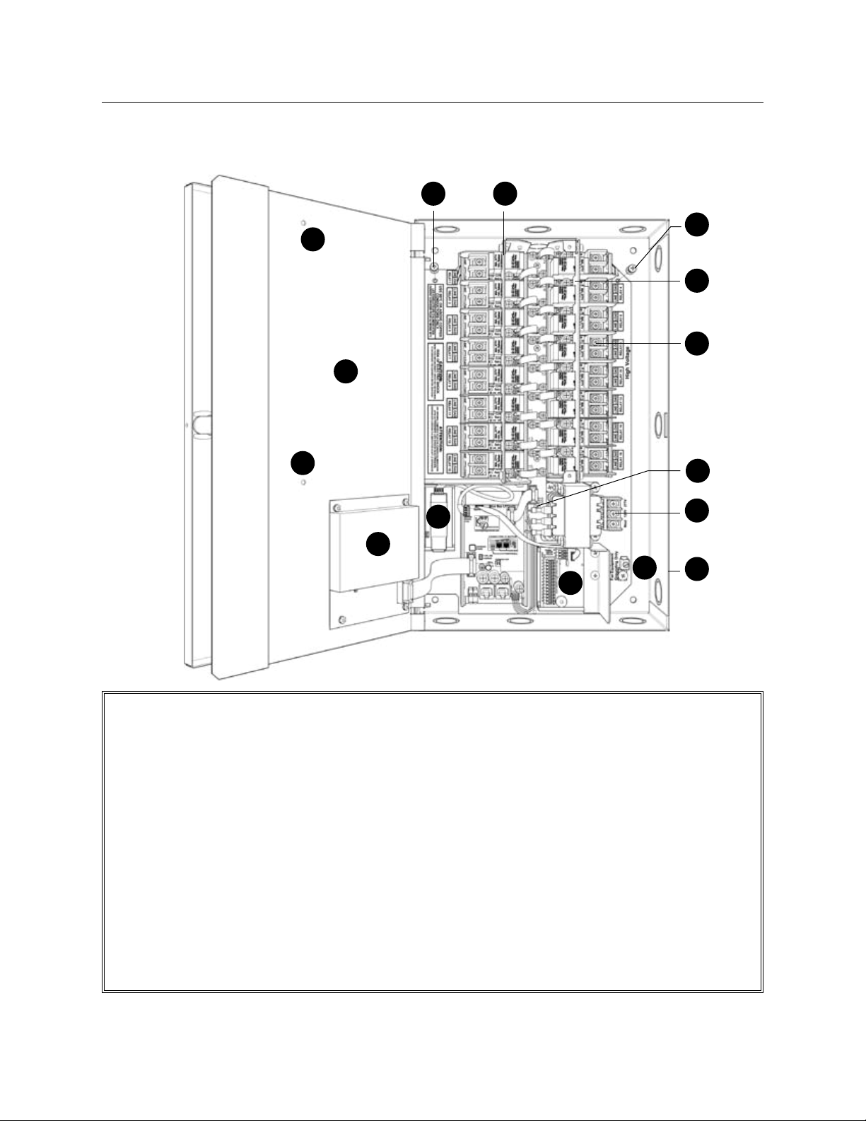
12 THE BLUE BOX LT OVERVIEW
1
1
2
8
6
3
9
4
11
6
9
7
6
10
5
GR1416 LT (WHITE DOOR OPEN)
Screw fastener secures hinged Control Panel 1.
Door (Master only).
Hinged Door Panel provides a barrier between 2.
Control Interface and High Voltage connections
beneath (Master only).
Optional Modem. Free factory dial-up programming3.
Optional DI contact closure interface card.4.
NEMA 1 surface mount enclosure with hinged 5.
door and key lock; Ø1/4" mounting holes at 4
places (hardware not included).
Optional: Unfasten three screws to remove chas-6.
sis assembly from enclosure providing full access
to mounting holes if required.
SnapLink7.
LED: ON when relay is OFF (NC).
DTC Clock / Display & Programming Interface: 8.
32-channel, 365-day astronomical clock with
Scroll and Tab to access control features for en-
.
tire system (Master only).
Voltage barrier separates low & line voltage con-9.
nections.
Dual Voltage Input: Blue Box LT10.
ther 120V or 277V.
Ground Lug for equipment grounding.11.
™
relays, Normally-Closed (NC). Status
™
operates on ei-
LCDBBO03Sept08
Page 13
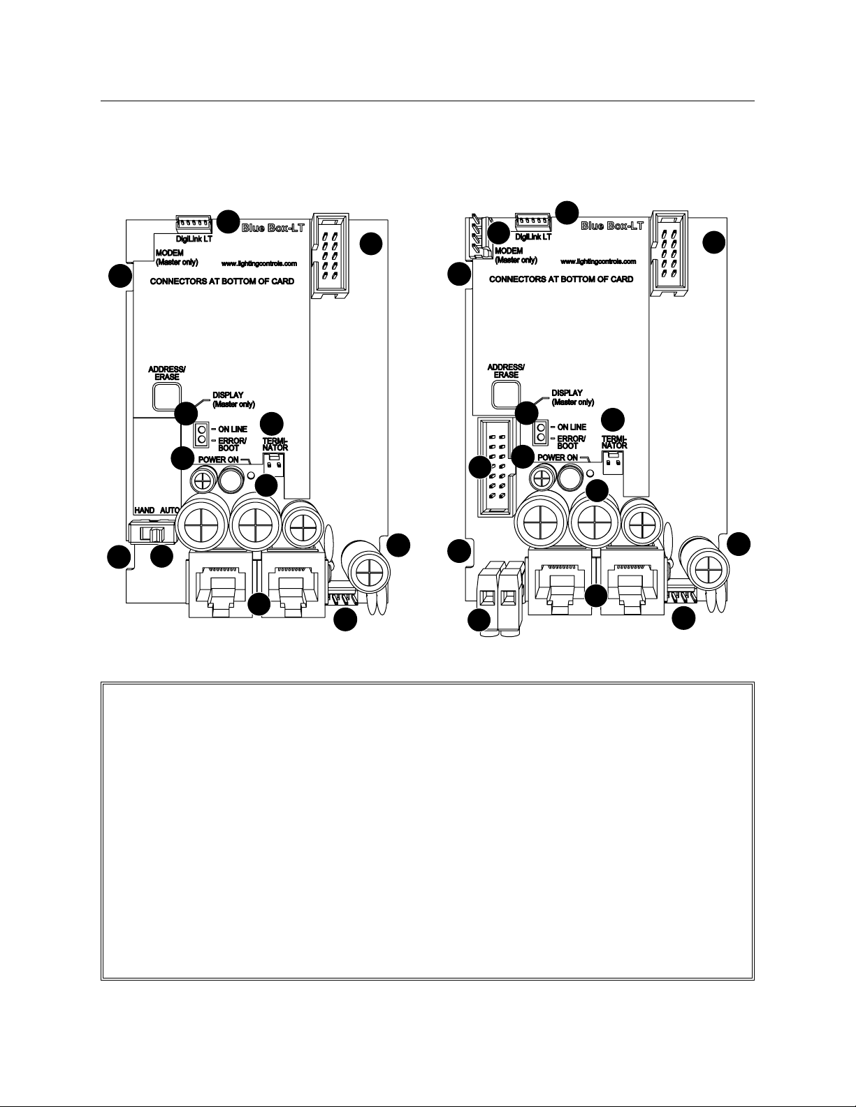
THE BLUE BOX LT OVERVIEW 13
GR1416 LT SLAvE PANEL RELAY CONTROL CARD GR1416 LT MASTER PANEL RELAY CONTROL CARD
7
7
12
11
9
4
2
10
8
13
1
7
7
7
3
6
5
11
9
4
1
8
10
7
2
13
LCDBBO03Sept08
Relay Drivers connect to Smacker Strip. Relay 1.
drivers will close latching relays upon loss of
power to the Control Card.
RJ45 sockets for digital bus. Digital devices (re-2.
lay panels, digital switches, etc) connect to this
panel using a bus (daisy-chain) topology.
Photocell por t (master panel only). +V output 3.
with a photocell input. Photocells are polarized
- follow color code.
Power/data connector for DI Card.4.
Power/data connector for modem (master panel).5 .
Power/data connector for DTC clock/display 6.
(master panel only).
Removal slots for control card. Used with a flat 7 .
blade screw driver to remove the Control Card.
Terminator pins. Add terminator here if this is 8.
an end-of-bus panel (per “System Star t-Up &
Cabling Guide”).
Online LED indicates the communications mi-9.
cro-processor is functioning, not that the panel
can see the digital bus.
Power ON LED indicates the control card is 10.
receiving power from the transformer and has
successfully converted it to DC.
Error/Boot LED. Flashing constantly if card can-11.
not boot on start up.
Hand/Auto Switch. (slave panel only) In Auto 12.
mode, relays will react to schedules and switches. In Hand mode, relays will remain closed.
Power input from transformer.13.
Page 14
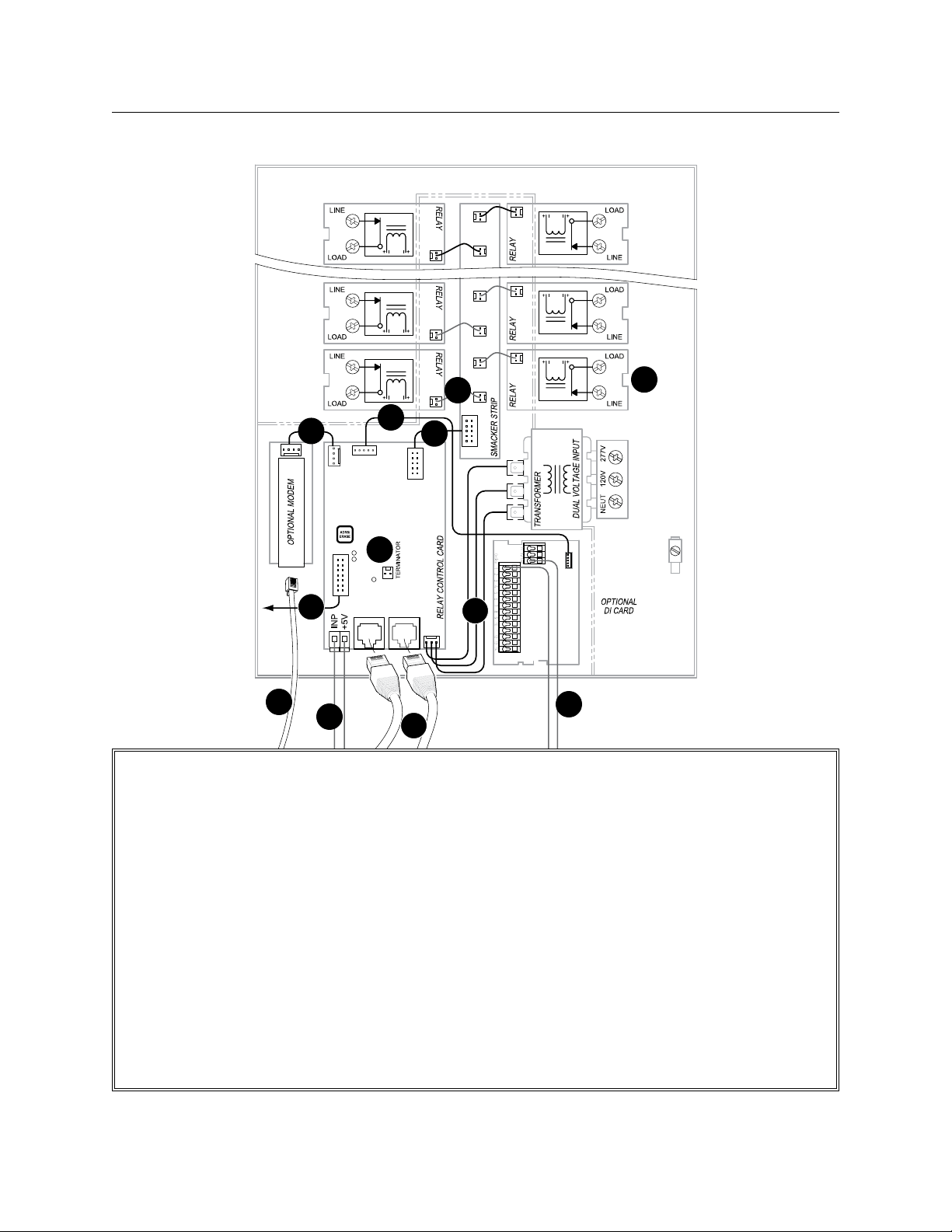
14 THE BLUE BOX LT OVERVIEW
3
5
6
4
7
2
8
9
GR1416 LT (DOOR OPEN) INTERNAL SCHEMATIC
3#18 AWG. Supplies power from transformer 1.
to relay control card.
14 conductor ribbon cable: carries control signal 2.
between DTC and relay control card (master
panel only).
2 conductor ribbon cable: carries control signal 3.
from smacker strip to relays - one per relay.
10 conductor ribbon cable: carries digital signal 4.
from relay control card to smacker strip.
5 conductor ribbon cable: carries digital signal 5.
from relay control card to (optional) digital input
card.
4#22 AWG carries RS-232 signal from (optional) 6 .
modem to relay control card (master panel only).
10
12
1
11
Terminator/terminator pins to terminate bus line.7.
External Connections
4#24 flat cable from modem to analog phone 8.
jack. Always note phone number of modem.
2#18 AWG to Blue Box photocell. Up to 300 feet.9.
Cat. 5 cable with RJ45 connectors links Blue Box 10.
to other digital devices (other blue box panels or
digital switches).
Contact closure inputs & DI card common 11.
“GND” + 1 #18 per input.
Line and load relay lugs.12.
For information about cabling for contact closure
switches or occupant sensors. Refer to DI Card
Installation Guide for options and details.
LCDBBO03Sept08
Page 15
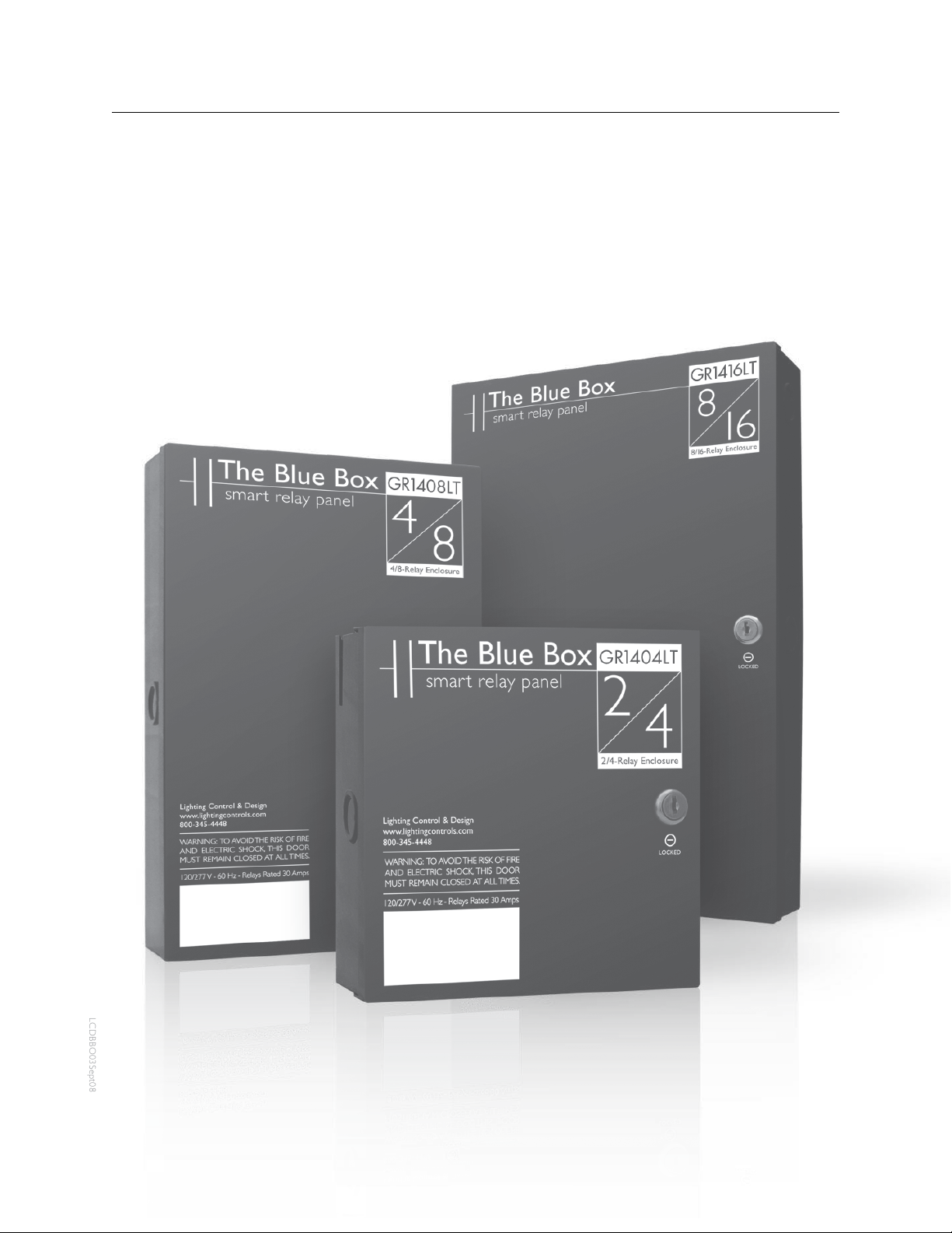
THE BLUE BOX LT OVERVIEW 15
INTRODUCTION TO THE BLUE BOX™ LT SERIES
The only panel you will ever need for small to medium projects - quicker to install than traditional lighting contactors and
much easier to configure. The Blue Box™ LT Series is UL Listed and complies with every energy code in the USA.
LCDBBO03Sept08
Page 16
16 THE BLUE BOX LT OVERVIEW
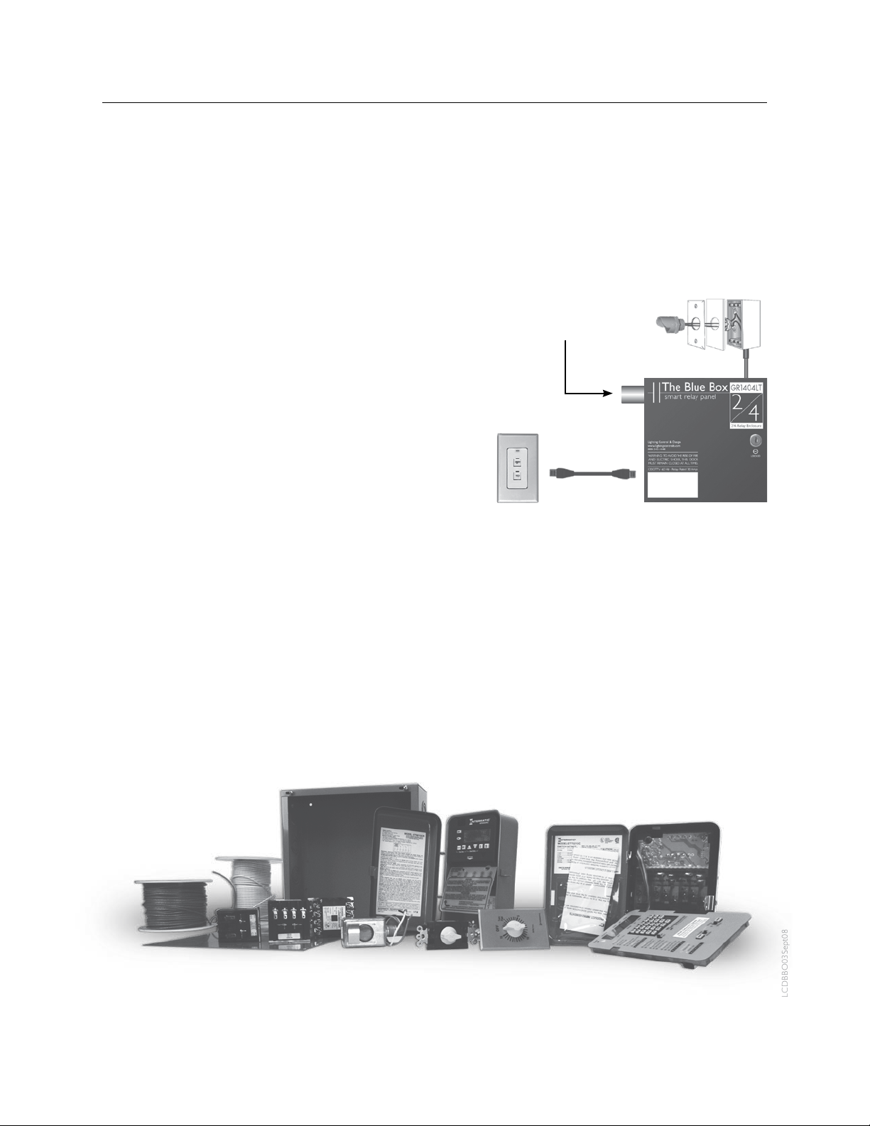
THE BLUE BOX™ LT vS. LIGHTING CONTACTORS
SMART RELAY PANEL
The Blue Box™ LT Series is the only panel you will ever
need for small to medium projects.
It is quicker to install than traditional lighting contactors as
well as more flexible.
With purchase of the optional modem you receive free
lifetime dial-up programming support from the factory.
Or you can connect remotely using our free software.
The Blue Box™ LT is part of the GR 2400 lighting control
system, from LC&D.
Control up to 16 devices.
DITCH THE OLD WAY OF DOING THINGS
Traditional lighting contactor panels require an electrical-mechanical assembly specific to the job at hand. This
means parts and pieces must be field-assembled and
field-programmed.
Any programming or hard-wire changes made to lighting
contactor panels require you to go back to the site.
Outdoor Photocell
Breaker Panel
Digital Override Switch
Master Relay Panel
LCDBBO03Sept08
Page 17
THE BLUE BOX LT OVERVIEW 17
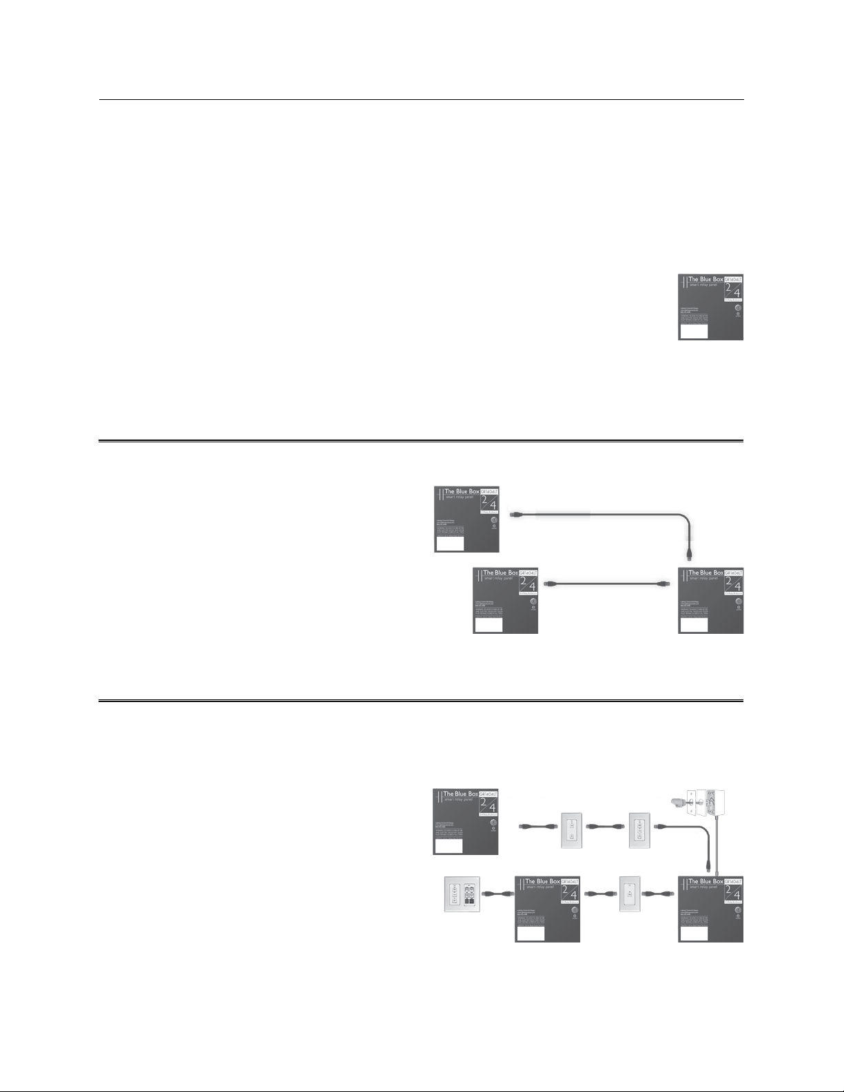
BUILD YOUR SYSTEM IN 3 STEPS
Every system must have a Master Panel which contains
the clock and photocell inputs and connections for the
optional modem.
STEP 1: MASTER PANEL
How many circuits (relays) do you need to control? (See
pgs. 6-7 for enclosure sizes).
Do you need a modem for remote dial-up programming?
(See pg. 10, “Modem”).
Do you need inputs for occupant sensors, or contact closure switches? (See pg. 10, “Digital Input Card”)
Each system needs one master panel. Use one Blue Box
for each electric room you are controlling lighting circuits in.
Slave Relay Panel
Master Relay Panel
™
STEP 2: SLAvE PANELS
For each additional Blue Box™ LT, how many circuits (relays) do you need to control? (See pgs. 6-7).
™
For each additional Blue Box
puts for occupant sensors, or contact closure switches?
(See pg. 10, “Digital Input Card”)
Up to 16 panels and switches may be controlled on the bus.
LT Series, do you need in-
STEP 3: SWITCHES, OUTDOOR PHOTOCELLS &
ACCESSORIES
How many override switches do you need?
How many buttons on each switch? (1 to 6 buttons cost
the same).
Will you need a photocell to supplement the DTC astro-
LCDBBO03Sept08
nomical clock? (See pg. 10, “Digital Photocell”).
Add other accessories as shown on pages 10-11.
Control up to 16 devices.
Slave Relay Panel
Slave Relay Panel
Chelsea
Digital Switch
Master Relay Panel
Outdoor Photocell
Slave Relay Panel
Master
Relay Panel
Page 18
18 THE BLUE BOX LT OVERVIEW
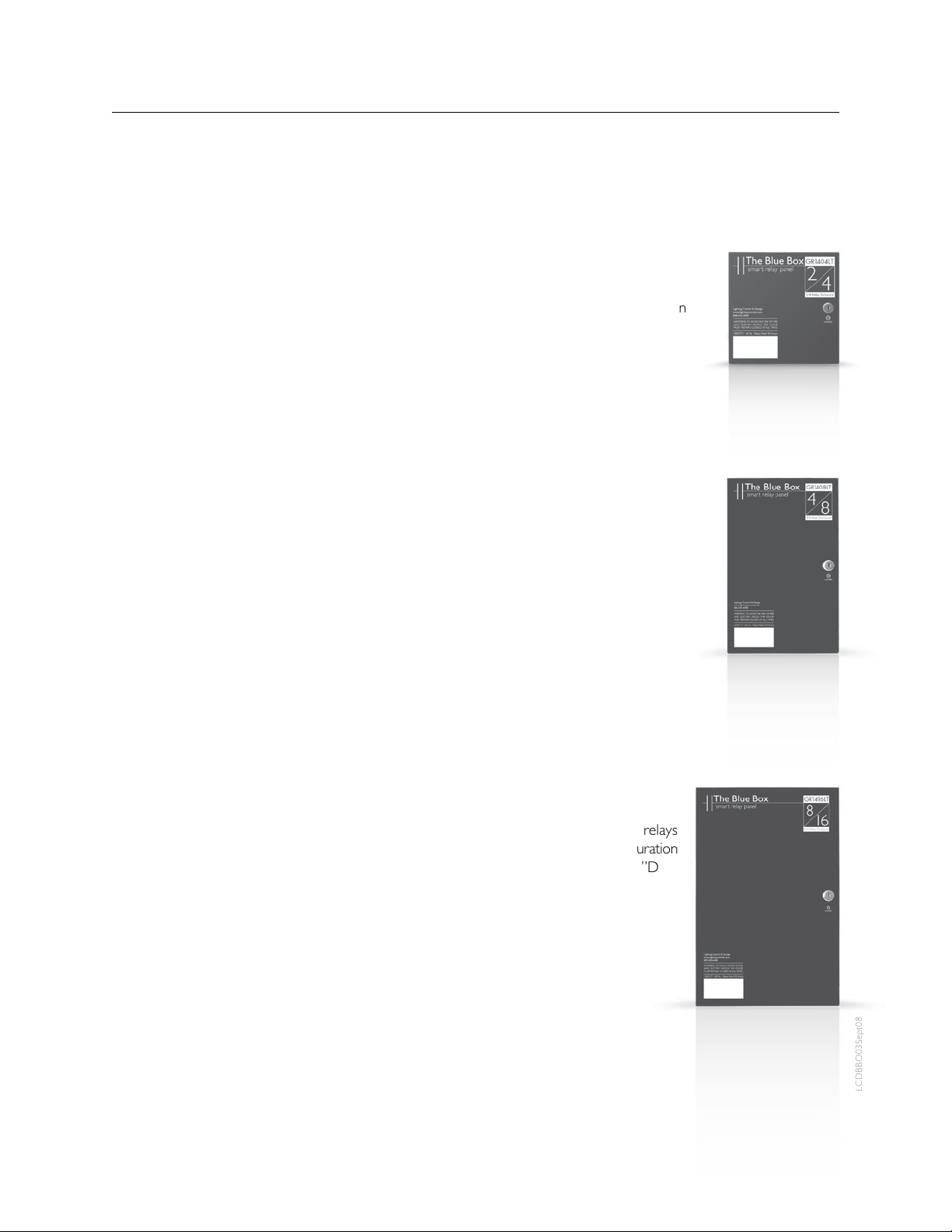
3 ENCLOSURE SIzES
DESIGNING WITH LIMITED SPACE?
The Blue Box™ LT Series comes pre-assembled and ready
for installation in three compact enclosure sizes!
This 100% digital panel can be programmed to operate
any lighting scenario and is equipped with a number of
accessory devices:
Easy energy code compliance•
277V, 30a relays UL Listed for 18,000 SCCR•
Competitively priced against lighting contactors •
and astronomical or multi-channel clocks
Digital Switches can turn relays on or off or over-•
ride time schedules for energy code compliance
Our simple, intuitive network connects multiple •
panels and switches using Cat. 5 with RJ45s
Panels can share the same time schedules and •
photocell
Additional relays can be purchased for partially •
filled panels.
Hinged locking door•
GR1404LT
Shipped with 2 or 4 relays•
Master or slave configuration•
8.4”H x 8.4”W x 3”D•
GR1408LT
Shipped with 4 or 8 relays•
Master or slave configuration•
13.4”H x 8.4”W x 3”D•
GR1416LT
Shipped with 8 or 16 relays•
Master or slave configuration•
17.1”H x 10.6”W x 3”D•
LCDBBO03Sept08
Page 19
THE BLUE BOX LT OVERVIEW 19
2 PANEL CONFIGURATIONS
MASTER RELAY PANEL
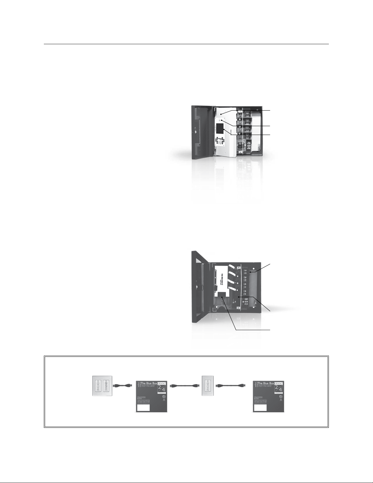
Each system needs one master panel equipped with: DTC
clock/programmer. Program schedules, switches and photocells for multiple panels.
365-day/7-day/astronomical 32 channel clock•
Plain English command prompts•
Non-volatile memory for all programming, 10 year •
battery back-up for time of day
Photocell Input: One photocell can control any relay in
any panel.
Optional modem and Digital Input Card (See pgs. 10-11,
“Accessories”).
Control up to 16 devices.
SLAvE RELAY PANEL
The slave panel is a fully programmable panel that networks to the DTC, modem, and photocell from the master panel.
No DTC, photocell input, or modem is required in a slave
panel, as it uses the master panel.
Option: Digital Input Card allows dry-contact closure
switches to control any relay in any panel – wall switches,
momentary switches, occupant sensors or any other dry
contact switch
(See pgs. 10-11, “Accessories”).
Master Relay Panel
Modem for remote programming
Optional Hand/Auto Switch
DTC clock/programmer
• 32 channel 365 day, 7
day astronomical clock
• Programming access for
time schedules, switches,
photocell etc.
• Large format screen
Slave Relay Panel
Lighting relays:
• 30A @ 277V Ballast
• 20A @ 120V Tungsten
• 20A @ 347V Ballast
• SCCR 18,000 Amps
Power supply:
• 120V/277V
RJ45s inputs for digital bus
LCDBBO03Sept08
Chelsea Digital SwitchChelsea Digital Switch
Master Relay Panel Slave Relay Panel
Page 20
20 THE BLUE BOX LT OVERVIEW
MOST POPULAR ACCESSORIES
These represent the most popular LC&D accessories. For a complete list of accessories refer to the LC&D Catalog.
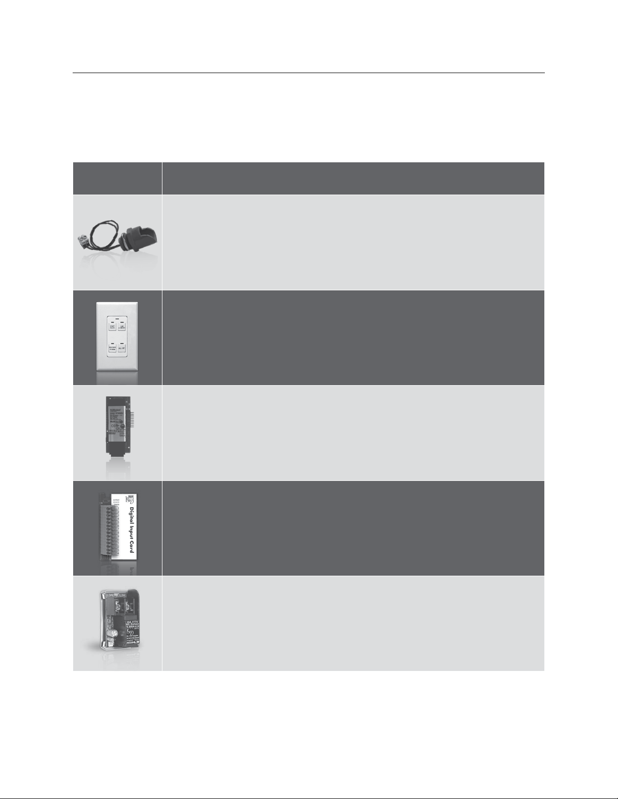
Product: Description:
Digital Outdoor Photocell (PCO): Connects to the master panel. Recommended for stormy
regions (where it may darken early) to supplement the astronomical clock.
Product Code: PCO
Chelsea Digital Switch: With 1, 2, 3, 4 and 6 buttons and free factory engraving. Ideal for override of automatic controls and manual control of lighting. Link with Cat. 5 cable with RJ45s.
Product Code: CH-1, 2, 3, 4 and 6
Modem: Allows you to make changes to the Blue Box™ LT remotely over dial-up. Or call our
technical support line and have us do it for you (for free) for the life of the system.
Product Code: MOD
Digital Input Card: Plugs into master or slave panels. For projects that require non-digital
switches, including: standard wall switches, center-off momentary switches, occupant sensors,
or any dry-contact closure. DI 6 inputs may be enabled / disabled over the bus.
Product Code: DI 6 or DI 14
SnapLink™ Latching Relay: Normally closed latching (NCL), UL listed for 30 amps lighting
(ballast, HID) at 277v, 20 amps at 347v and 20 amps Tungsten at 120v, 18,000 amp SCCR at
277v, rated 250,000 on/off cycles, 3 yr. warranty.
Product Code: SLNC or SLNO
LCDBBO03Sept08
Page 21
THE BLUE BOX LT OVERVIEW 21
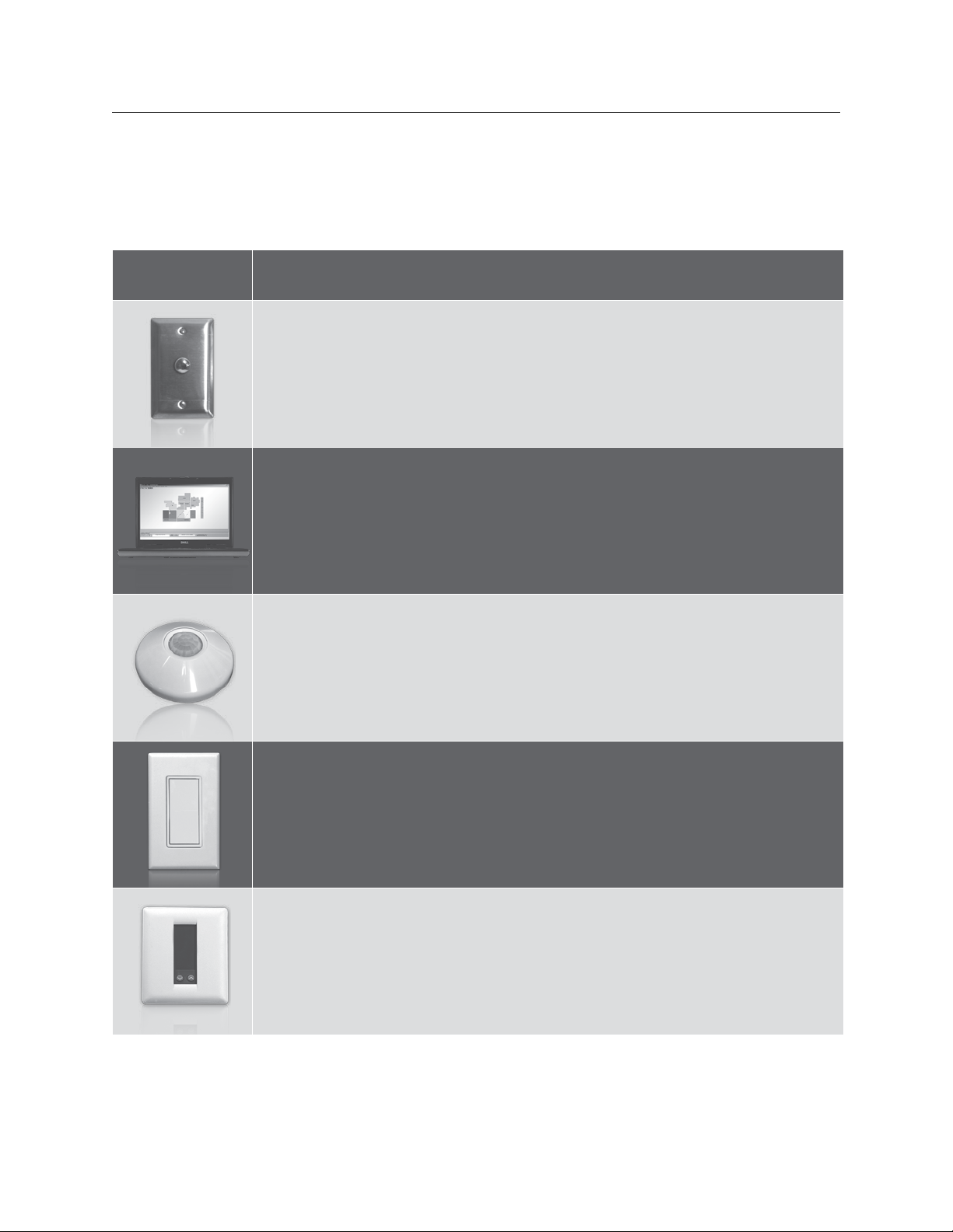
The accessories below may not be available as a stocking product, but can be ordered.
Product: Description:
SwitchBolt: One or two vandal resistance buttons per gang. Switches can be mounted outdoors or almost any location.
Product Code: SB-1 or 2
Link-To PC/Ethernet: Connect multiple computers to the GR 2400 system from any RS232,
USB port or an ethernet network connection.
Product Code: L2-PC
LCDBBO03Sept08
Occupant Sensors: A full line of sensors. One sensor can control any relay(s) in any panel(s).
Occupant sensors require a Digital Input Card.
Product Code: (Contact LC&D factory)
Digital Rocker Switch: Looks like a regular decora style switch; operates like a 2-button digital
switch.
Product Code: RS
Digital Thermostats/T-Link: A single T-Link card can control up to 32 digital thermostats (heatpump or multi-stage).
Product Code: T-LINK (Contact factory for T-STAT ordering.)
Page 22
22 THE BLUE BOX LT OVERVIEW
APPLICATIONS
See how easy it is to design and install the Blue Box™ LT in
different applications. We stand behind each of our products with a 3 year warranty.
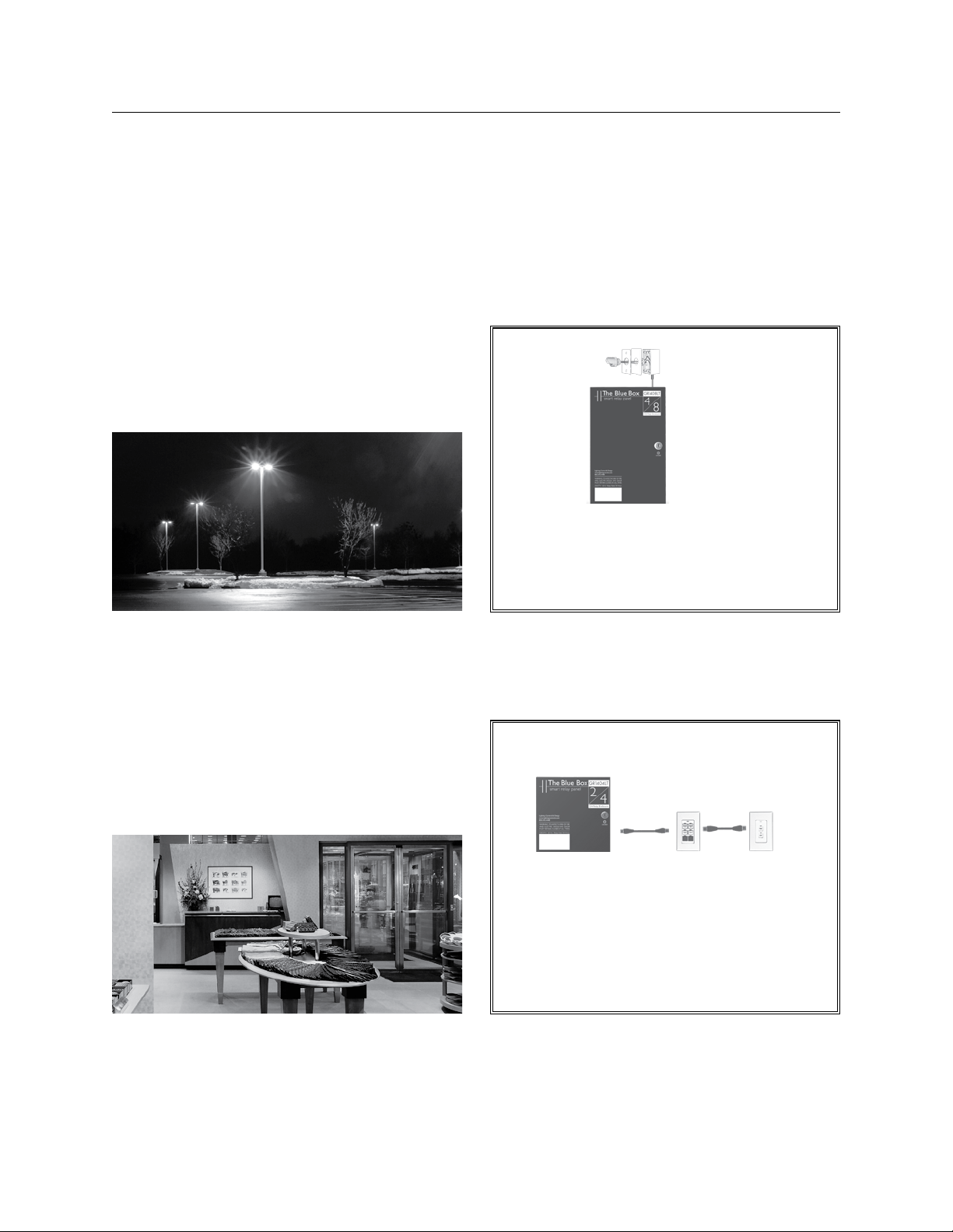
SMALL PARkING LOT (SINGLE CONTROL PANEL)
Select a master panel with the correct number of relays.
The DTC astronomical clock does the rest. Order an outdoor photocell (PCO) as a back up for stormy days (not
required for code compliance).
GR1408LT master was compared to a equivalent
assembly of lighting contactors and a multi-channel astronomical clock. The Blue Box
less expensive than the lighting contactors!
Outdoor Photocell
Master
Relay Panel
™
LT was 50%
RETAIL STORES (WITH 6 OvERRIDE zONES)
Separately zone lighting circuits to comply with local
codes, and use the DTC clock to schedule the off-sweeps.
A multi-button digital switch is the override and manual
control, and complies with energy codes.
Master Relay Panel
Digital Override Switches
The Blue Box™ LT was compared to similar package of (4) 2-pole lighting contactors, a multichannel clock and twist-timers: The Blue Box™ LT
Series was 60% less expensive than the lighting
contactors!
LCDBBO03Sept08
Page 23
THE BLUE BOX LT OVERVIEW 23
APPLICATIONS (Continued)
How Does the Blue Box™ LT Series Stack-up? In a nationwide survey of Electrical Contractors, the cost to
purchase and field-assemble lighting contactor panels was
compared to the cost of the Blue Box™ LT Series.
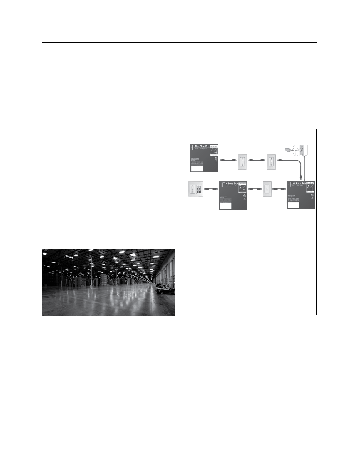
WAREHOUSE (MULTIPLE CONTROL PANELS)
Locate multiple Blue Box™ LT panels and digital switches
where you need them and then link them with Cat. 5 cable.
One Blue Box™ LT master (with a Digital Time Clock
(DTC) can control relays in multiple slave panels and digital switches (up to 16 digital devices).
Digital switches are used for manual control and afterhours override.
A photocell can be used as back up for outdoor lighting, or
even as a simple daylight harvesting system for skylights.
Check your local codes for how large an area each switch
can override.
If you are unsure, visit www.lightingcontrols.com for a free
code excerpt for your state.
Slave Relay Panel
Slave Relay Panel
Chelsea
Digital Switch
The Blue Box™ LT Series system shown above was
compared to multiple lighting contactor panels
(each with a multi-channel clock), manual switches,
twist-timers, and photocells.
The Blue Box™ LT Series was 64% less expensive!
Outdoor Photocell
Master
Relay Panel
LCDBBO03Sept08
Page 24

24 THE BLUE BOX LT OVERVIEW
BLUE BOX TECHNICAL SUPPORT
AFTER-MARkET SUPPORT
The Blue Box™ LT Series comes with LC&D’s top-notch
customer suppor t and, when connected to a phone line,
includes free lifetime dial-up programming.
Make changes to the Blue Box™ LT Series remotely (with
purchase of a modem) over dial-up. Or call our Technical
Support line and have us do it for you (for free) for the
life of the system.
DITCH THE OLD WAY OF DOING THINGS
Traditional lighting contactor panels require an electrical-mechanical assembly specific to the job at hand. This
means design, parts/pieces and assembly time. Any customer changes require re-wiring and re-assembly.
LIGHTING CONTROL & DESIGN
905AllenAve•Glendale,CA91201•Support800-345-4448•www.lightingcontrols.com
LCDBBO03Sept08
Page 25

MAINTENANCE
& TROUBLESHOOTING
MAINTENANCE & TROUBLESHOOTING
Making Up Cat. 5 with RJ45 Connectorsa)
Adding a New Deviceb)
Parts Replacement Guidec)
Hardware Troubleshootingd)
LCDBBO&M03Sept08
Page 26

LCDBBO&M03Sept08
Page 27

®
™
THE BLUE BOX
LT
MAKING UP CAT.5
CABLE WITH RJ45
CONNECTORS
LCDBBMUCAT03Sept08
®
Lighting Control & Design
905 Allen Ave, Glendale CA 91201
•
Tel: 800-345-4448
www.lightingcontrols.com
Page 28

28 THE BLUE BOX LT MAKING UP CAT. 5 CABLE WITH RJ45 CONNECTORS
TABLE OF CONTENTS
Introduction .......................................................................................29
Ethernet Network ................................................................................29
The GR 2400 Bus and RS485 Communications Protocol................................................30
Cable and Crimping Quality .......................................................................31
The Importance of a Proper Crimp..................................................................31
Type of Wire .....................................................................................31
The Ideal Scene: Professionally Made Commercial Cables ...............................................32
Reasons Why It’s Hard to Make Good Crimps on RJ45s ............................................33
Solid Wire is Ductile...............................................................................33
The Right Crimping Tool ...........................................................................33
The Right Modular Connector ......................................................................34
How to Make Proper Crimps ......................................................................35
Sequence of Actions ..............................................................................35
Miscellaneous Information .........................................................................37
Cable Kinks ......................................................................................37
Dirty RJ45 Sockets ................................................................................37
Summary ........................................................................................38
Stable Datums on Crimping Cat. 5...................................................................38
LCDBBMUCAT03Sept08
Page 29
THE BLUE BOX LT MAKING UP CAT. 5 CABLE WITH RJ45 CONNECTORS 29
INTRODUCTION
All Lighting Control & Design systems use Cat. 5 cable with
RJ45 connectors to network devices. While both our system & Ethernet networks use Cat. 5 cabling, there are huge
differences between the two (Note: Cat. 6 is often substituted for Cat. 5. Our system accepts either type of cable.)
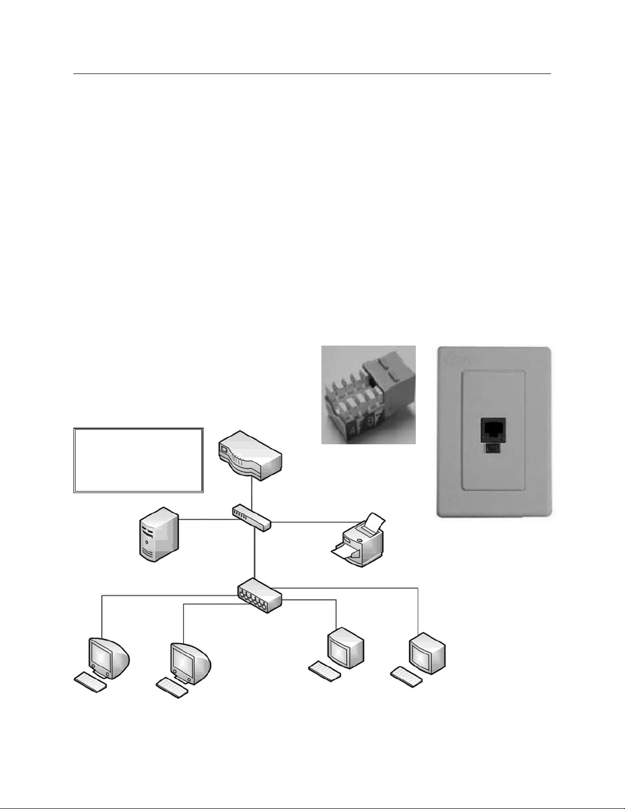
ETHERNET NETWORk
Typically Ethernet networks have multiple devices connected to a central point, this design scheme is called a
star topology (Figure 1.1 illustrates a multi-level star topology). In this example, the four workstations are connected directly to a switch/hub, which is connected to another
star to access either the file server, printer or router.
The hub/switch receives the data sent by the four workstations; upon receipt of the data, the hub/switch checks
the data for errors and re-transmits to another switch to
access the other devices on the network. The data travels
only one section of the cable before it gets cleaned up or
repeated and forwarded to another point. Thus any incon-
Figure 1.1 - Typical Ethernet Network Setup
Ethernet uses Cat. 5 cables,
each cable does not exceed
100 meters (330ft).
Router
sistent quality in the Cat. 5 cable or crimp will not severely
impact this network’s stability. It may slow the data transmission on one leg of the network, but not as to affect the
other nodes on the network.
In an Ethernet network, one cable is connected to the
switch, workstation, printer, etc. and terminated at a jack
socket in the wall (Figure 1.2a and 1.2b). This socket has
insulation displacement connections, which do not require
crimping. The cable from the wall socket to the device is
typically a factory-manufactured cable. These cables use
flexible stranded wires and crimps made on pneumatic
crimping machines, which exert several hundred pounds
of pressure to ensure an excellent crimp.
Figure 1.2a: Insulation
Displacement Socket
LCDBBMUCAT03Sept08
Switch
File Server
Switch/Hub
Workstation 1 Workstation 2 Workstation 3 Workstation 4
Printer
Figure 1.2b
Page 30
30 THE BLUE BOX LT MAKING UP CAT. 5 CABLE WITH RJ45 CONNECTORS
INTRODUCTION (Continued)
THE GR 2400 BUS AND RS485
COMMUNICATIONS PROTOCOL
LC&D devices communicate using a method known simply as half duplex RS485. This data communication method uses one twisted pair of the stranded Cat. 5 cable to
transmit data; and the other three pairs to carry power to
the switches.
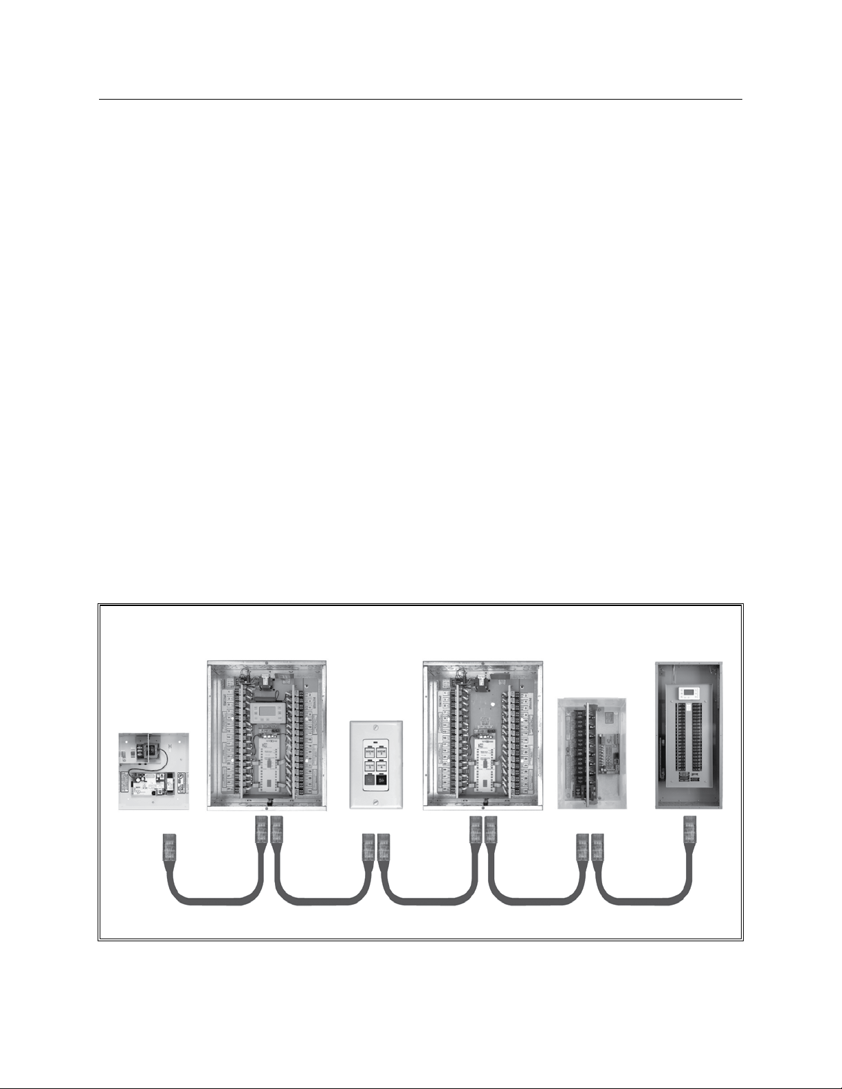
All devices are connected in a single line (or bus). This
RS485 network allows multiple items on a bus to be connected in parallel, also called “Daisy Chain” wiring.
Each item on our system has two RJ45 jacks that allow the
cabling to come in on one side and go out the other.
To illustrate the “daisy chain” method, Figure 1.3 shows a
diagram of an LC&D GR2400 lighting control system.
One can see how a bad connection, say at the digital
switch, can prevent communication from the Master Panel
/DTC from reaching the rest of the bus.
Small imperfections in the Cat. 5 cable crimps tend to be
the most common “bad connections.”
Though a single imperfection may only slow down the
communication by a small margin it gets multiplied up
over the length of the chain.
RJ45 connectors simplify the wiring and connections of
our system, but the impor tance of having a good crimp
is paramount.
Figure 1.3
Uplink
™
Card
GR 2400
™
Master Panel
Chelsea
DigitalSwitch
GR 2400™ Slave Panel
MicroPanel
™
SmartBreaker
™
GR 2400 Master Panel GR 2400 Slave Panel SmartBreaker Panel
™
Panel
LCDBBMUCAT03Sept08
Page 31
THE BLUE BOX LT MAKING UP CAT. 5 CABLE WITH RJ45 CONNECTORS 31
CABLE AND CRIMPING qUALITY
THE IMPORTANCE OF A PROPER CRIMP
Imperfections in a crimp adds a resistive and capacitive load
at that point in the network. For example, if the voltage is
dropped to 75% of its previous value at each crimp, the
signal voltage will drop from 5V to 3.75V on the first crimp
and 2.8V after the second.
Therefore, multiple bad crimps can cause the signal to be
lost in the noise threshold after consecutive voltage drops;
this loss of signal through the length of a cable is called
attenuation. Impedance is the measurement of cable
resistance to a signal, measured in ohms.
If the RJ45 connectors are improperly terminated, the
additional resistance and capacitance at the connector
changes the “character” of the wire causing what is called
an impedance mismatch.
Impedance mismatch causes signal attenuation because
part of the transmitted signal is reflected back much like
an echo and does not reach the receiver. Inconsistent
crimps compound these effects and cause a larger part of
the signal to be reflected back.
When these reflected signals collide with the first
discontinuity, part of the signal will return to the original
direction and create multiple echo effects. This results in
an “unstable bus” because these reflections or echoes
make it difficult for our devices to receive data.
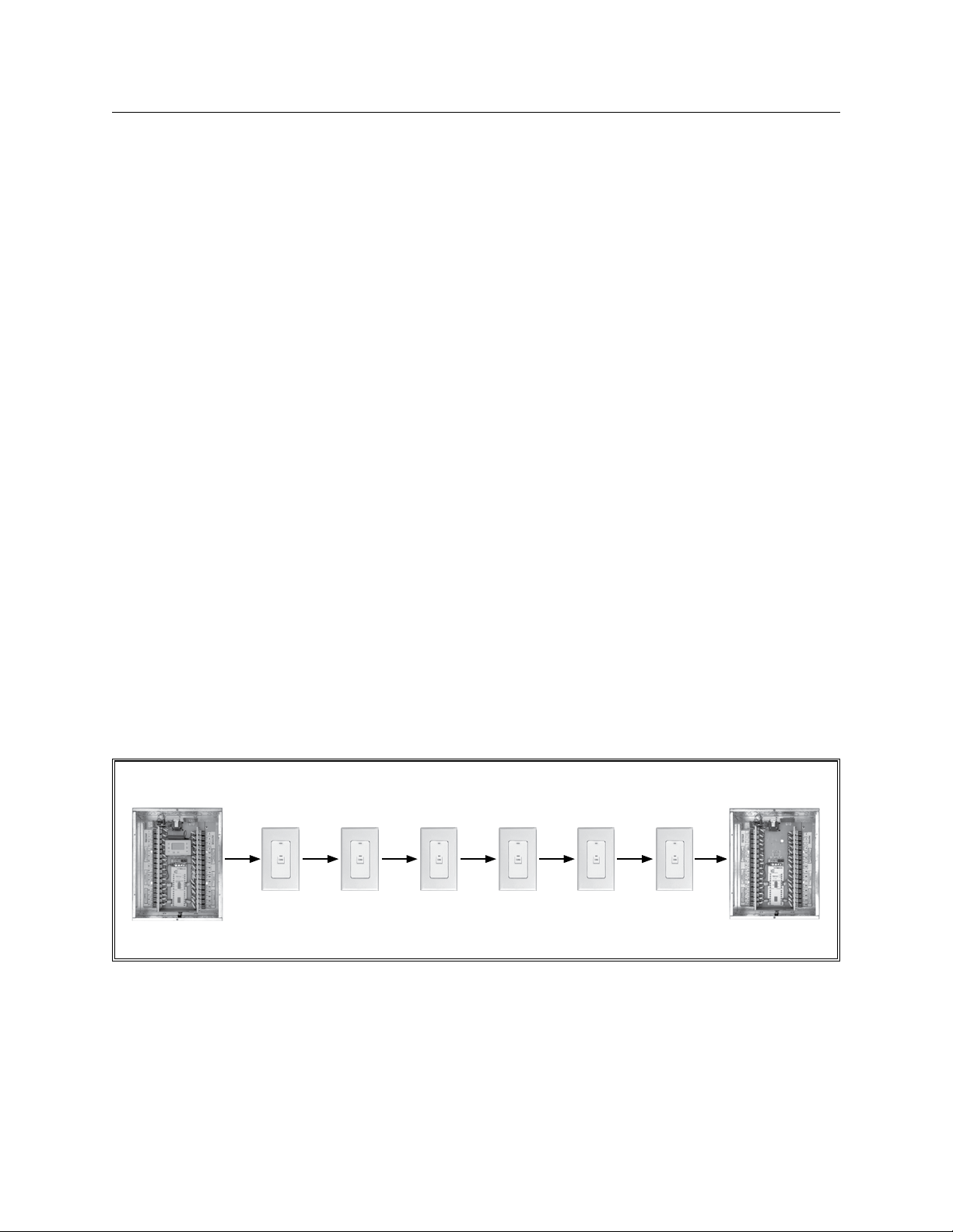
Figure 1. 4 shows a daisy-chained network; if there are bad
crimps as described above the transmitted signal from the
relay panel can lose strength with every device.
TYPE OF WIRE
There are three types of wire that use RJ45 crimped
connectors. The first is a flat telephone cable, made of 26
gauge wires. It is not Cat. 5 since the wires all run parallel to
each other and are not twisted and thus lack immunity to
noise. We use this type cable for low frequency signals and
short distances, such as to provide power to the clock.
The other two cables are round in form. They come in
stranded and solid varieties. The stranded wires are used
for “patch cables” from a computer to a wall socket.
LCDBBMUCAT03Sept08
Figure 1.4
Page 32
32 THE BLUE BOX LT MAKING UP CAT. 5 CABLE WITH RJ45 CONNECTORS
CABLE AND CRIMPING qUALITY (Continued)
Stranded wire does not fatigue as easily and break. Solid
wire is usually used as “building wire.” The reason being
that it used to be cheaper and is not usually flexed after
it has been installed. LC&D only recommends the use of
stranded Cat. 5 wire.
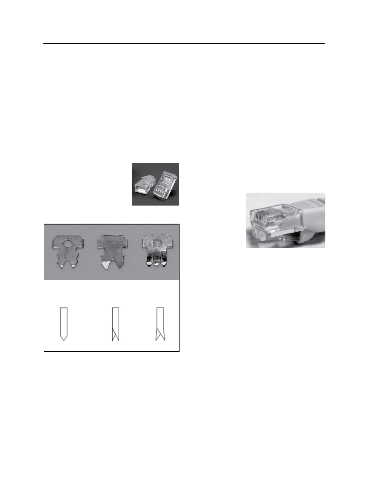
The three types of wire have three types of crimps
(Figures 1.5a & 1.5b show an RJ45 connector and three
cable crimp types):
Contacts for Stranded wires
C
ontacts
for Solid/Stranded wires
C
ontacts
for Solid wires.
Figure 1.5a
THE IDEAL SCENE: PROFESSIONALLY MADE
COMMERCIAL CABLES
Common attributes of commercially made cables include:
They always use stranded cable.a)
The pneumatically crimped connectors have per-b)
fectly flat contacts.
The strain reliefs are usually injection molded.c)
Figure 1.6 illustrates an example of a commercial cable.
Take note of the injection molded strain relief. This prevents any movement of the connector from the cable
to ensure the cable
crimp stays engaged.
Figure 1.6
Stranded Only Solid / Stranded Solid Only
Figure 1.5b
(Note: It is very important that the correct crimps/
contacts are used for the right wire! The contacts that
mate with the wires have different shapes for the different
types of wire).
LCDBBMUCAT03Sept08
Page 33
THE BLUE BOX LT MAKING UP CAT. 5 CABLE WITH RJ45 CONNECTORS 33
REASONS WHY IT’S HARD TO MAkE
GOOD CRIMPS ON Rj45s
There are two components needed to crimp a Cat. 5 cable:
a “crimper” and a “RJ45 modular connector.” A crimper is
the tool used to make a crimp and seal the cable to the
connector. RJ45 connectors create the interface for a connection and come in four sizes : 4-, 6-, 8-, and 10-position
(position is the placement in the connector that holds a
contact [pin]).
It is important to note, all crimpers and connectors are
not created equal. We have performed many trials to determine a recommended crimper tool and connectors for
our systems; these products will be discussed in a later
section.
Note that no matter what brand of connector or crimp
tool used, just the action of crimping a connector to a
cable can cause it to deform and splay the connections.
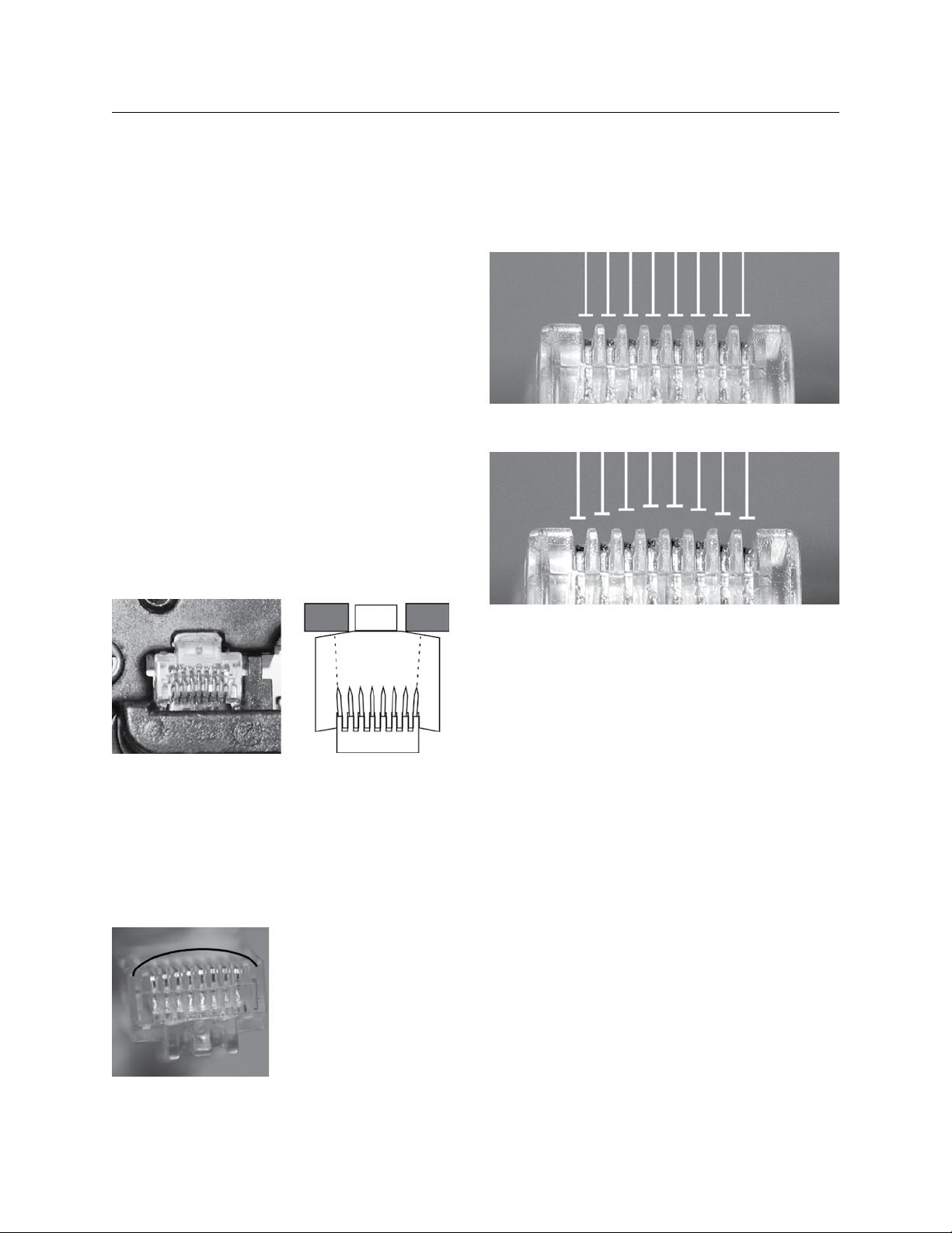
Figure 1.9a: Contacts are seated properly.
Figure 1.7a
Figure 1.7a illustrates how the crimper head pushes the
contacts down by the same distance but deforms the
plastic case under the pressure; as you see in Figure 1.7b
the contact causes the center crimp to not be adequately
supported or seated. Figure 1.8 shows a crimp after
release; notice how it has a “bowed” appearance.
Figure 1.8
LCDBBMUCAT03Sept08
Figure 1.7b
A bowed crimp is a recipe for
disaster. The two center pins
do not have adequate contact
with the wire. And for the
purpose of LC&D lighting
systems, the two center pins
carry the data! The ONLY
way to completely flush the
Figure 1.9b: Contacts are not seated properly.
center pins is to crimp multiple times (Note: we suggest
5-10 crimps for a successful Cat. 5 cable crimp) (Figure 1.9a
and 1.9b are examples of properly seated and non-properly
seated contacts).
SOLID WIRE IS DUCTILE
The action of pulling a cable side to side does two things: a) pulls
the side wires out of the crimp and/or b) squashes the copper
wire, first one way and then another. The copper “flows” into
a new shape and stays there as if it has been hammered
flat. An example of this pulling occurs unintentionally when a
switch is pushed/forced into a tight space or wall enclosure.
This can result in an “open” connection. This is why we do not
recommend solid wire cable.
THE RIGHT CRIMPING TOOL
Choosing the right crimping tool is the most critical part
of a cable crimping job. All crimping tools do pretty
much the same thing, they force the contacts within the
connectors onto the cable. But as we mentioned earlier,
there is a big difference in the quality of crimps on different
types of crimping tools. In trial testing, we found even the
Page 34
34 THE BLUE BOX LT MAKING UP CAT. 5 CABLE WITH RJ45 CONNECTORS
REASONS WHY IT’S HARD TO MAkE
GOOD CRIMPS ON Rj45S (Continued)
expensive, solidly made crimping tools did not make good
crimps. The best and recommended crimper is provided
in the LC&D Crimping Kit. This crimping tool has no “stop”
feature. The no “stop” feature allows “over-crimping”
to ensure the wires are seated correctly; and thus it is
possible to get the center contacts properly engaged.
THE RIGHT MODULAR CONNECTOR
After much research, we found a modular connector that is
easy to setup and makes it possible to crimp a perfect Cat.5
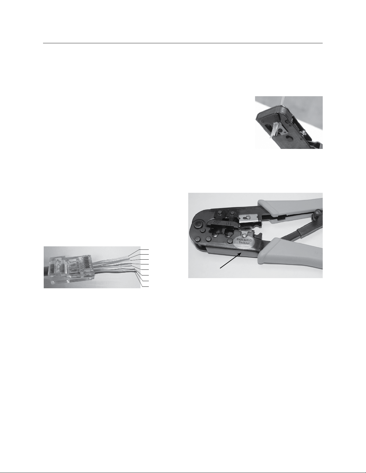
cable every time. The brand is “EZ RJ45” (shown in figure
1.11). It allows for faster terminations and is compatible
with our crimper tool.
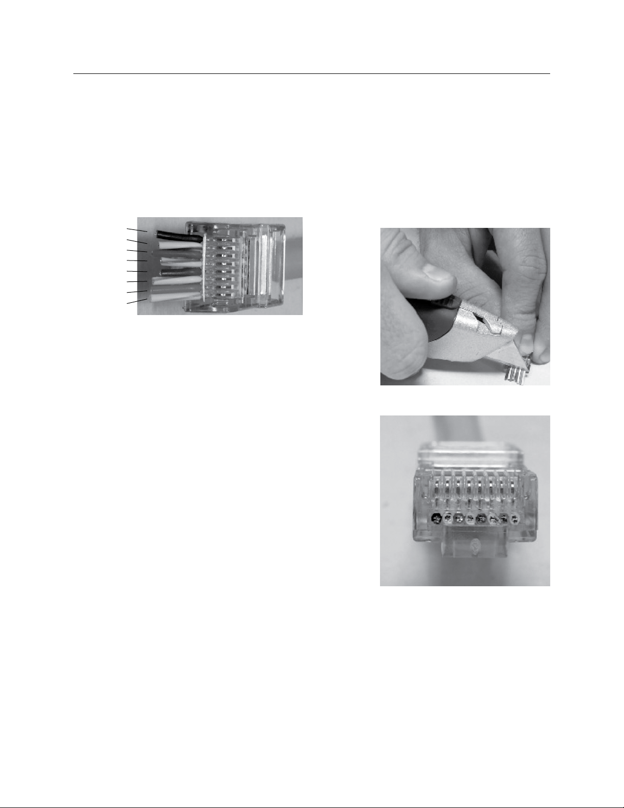
The EZ RJ45 crimp has holes in the front of the connector
which allow the 24AWG wire to protrude from the end
prior to crimping. (shown in figure 1.11) This will ensure
proper wire color arrangement and will also ensure that
the wires will be pushed all the way into the end of the
RJ45 connector.
White/Orange
Orange
White/Green
Blue
White/Blue
Green
White/Brown
Brown
Figure 1.11
The “EZ RJ45 Crimping Tool” (shown in Figures 1.12a and
1.12b) is specifically designed for these connectors and
will cut through the excess wires protruding from the end
of the RJ45 connector when crimped down.
It has some professional features such as the large crimping head but it is not capable of “over-crimping” to ensure
that the center conductors have really been engaged.
Though this crimper is very convenient; it will NOT make
good crimps. Use only the ratcheting crimper provided in
the LC&D Crimping Kits. Thus it may ONLY be used as an
initial crimper/cutter and then give the crimp multiple hits
with our recommended ratcheting crimper.
One can use the “EZ-RJ45” connectors with any crimper. It
just requires that the excess wire is cut off very close to the
end of the connector; this can be done with flush cutters.
Care must be taken to
prevent any excess wire
protruding from the end
of the connector since
this will prevent the
connector from seating
properly in the jack.
There are two wiring
standards used for making Cat.5 cables; 568A and 568B. Either one may be used,
as long as it is consistent along the bus. This manual references the 568B convention in the examples and images.
Patented Taiwan
This crimper is available in the LC&D
crimper kit. It is also private labeled
under many brand names.
Figure 1.12a
Figure 1.12b
LCDBBMUCAT03Sept08
Page 35
THE BLUE BOX LT MAKING UP CAT. 5 CABLE WITH RJ45 CONNECTORS 35
HOW TO MAkE PROPER CRIMPS
SEqUENCE OF ACTIONS
Always use STRANDED cable! a)
Only use “EZ-RJ45” brand connectors!b)
Proper preparation of the wires is very important. c)
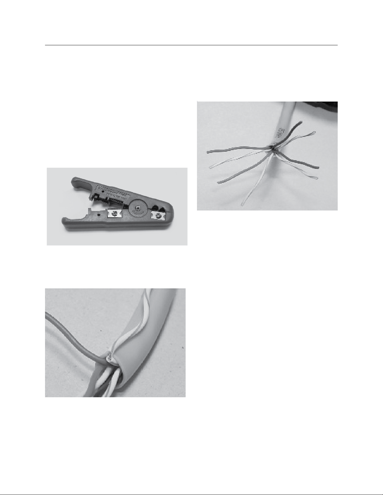
Our kit comes with a wire stripper and cutter that
is separate from the crimper (Figure 1.13 shows a
standard wire stripper/cutter)
Figure 1.13
Figure 1.15
LCDBBMUCAT03Sept08
Use a very light touch with the wire jacket stripper d)
tool. Inspect the conductors for nicks, it is easy to
nick the wires inside the jacket. This is especially
true with stranded cables.
Figure 1.14
Untwist all four pairs and straighten/smooth out the e)
kinks (as shown in Figure 1.15).
Now put the wires in order. It is really easy to remember
the order with the following stable datums.
i. Every white/color wire is followed by a solid
color wire.
ii. Start with White/Orange.
iii. The two center pairs (Green and Blue) straddle
each other with the blue in the middle.
iv. The order goes as follows:
White/Orange
Orange
White/Green
Blue
White/Blue
Green
White/Brown
Brown.
Once the wires are all in line, hold them solidly about ½
inch from the insulation and cut straight across the wires
to get even ends. The twists in the wires are hard to
smooth out at the very end so cutting prevents the wires
crossing up once inside the connector.
After cutting the wires do not let go of the insulation before pushing the wires into an EZ-RJ45 connector - make
Page 36
36 THE BLUE BOX LT MAKING UP CAT. 5 CABLE WITH RJ45 CONNECTORS
HOW TO MAkE PROPER CRIMPS (Continued)
sure the locking prongs are facing down. Make sure that
the insulation is well under the strain relief and that the
wires are in the right order.
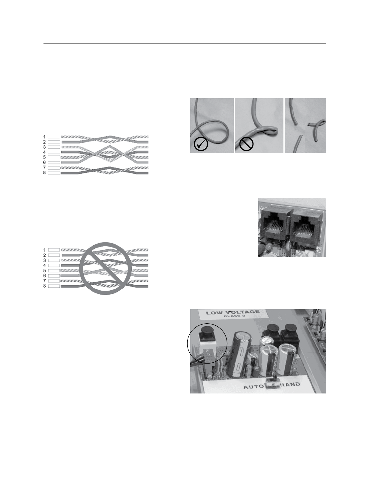
Brown
White/Brown
Green
White/Blue
Blue
White/Green
Orange
White/Orange
Figure 1.16
Figure 1.16 shows an example of the proper wire sequence (from right to left):
f) Depending on preference one can cut the ends of
the wires off at this point or after they have been
crimped. The positive of cutting the ends off right
now is that one can use flush cutters and then pull
the wires back into the connector so that they are
just inside prior to crimping. This may be easier
than cutting the wire after being crimped. Having
the wires protrude before being cut off allows one
to do a double check to make sure that the color
code is correct.
g) Crimp the connector multiple times, we
recommend at least 5 to 10 times. (Note: Fast
hard crimps will help the contacts seat better than
slow crimps. )
h) Visually inspect the crimp! Crimps must NOT
be bowed or arched. If they are, hit them again
multiple times with the ratcheting crimper.
i) If the wires have not been cut short as shown in
figure 1.16, the excess wire has to be cut off right
next to the connector. We want to make sure there
are no stubs protruding that prevent the crimp from
latching into a jack (see figure 1.17).
Figure 1.18 shows front view of a correctly made
Cat. 5 cable. Observe that none of the strands
are in a position to short to another strand or
cause problems.
j) Assemble the other end the same way for a straight
through cable. Test each cable for continuity using a
LAN tester. While testing, wiggle and tug to verify
a solid crimp.
Figure 1.17
Figure 1.18
LCDBBMUCAT03Sept08
Page 37
THE BLUE BOX LT MAKING UP CAT. 5 CABLE WITH RJ45 CONNECTORS 37
MISCELLANEOUS INFORMATION
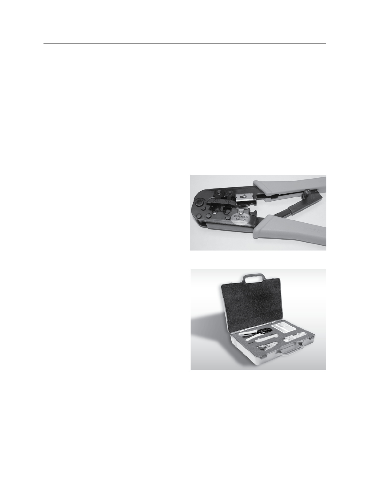
Our cables are made up as “Straight Through” cables. The
connectors at each end look identical. Notice that the
green pair straddles the blue while the orange and brown
take up the edges.
White/Orange
Orange
White/Green
Blue
White/Blue
Green
White/Brown
Brown
Never ever have a mixed pair on pins (4) and (5). Such as
Blue on (4) and White Green on (5). This will cause major
data loss. It is hard to find since the cable tester will tell
you that the cable is OK.
An additional comment on cable testers. They only tell
you if the wires have continuity from one end of the cable
to the other and that they are in the same order at each
White/Orange
Orange
White/Blue
Blue
White/Green
Green
White/Brown
Brown
end. They do not tell you if you have good crimps or if
your cables will work. The cables are part of the GR 2400
system. They are the par t of the system that is manufactured in the field. Thus LC&D has the least amount of
control over it. We have had cables that were tested with
high end, high frequency equipment that pass individually
but when plugged in end to end, the system did not work.
visual inspection of each crimp however showed bowed
crimps. When corrected the system was fine.
DIRTY Rj45 SOCkETS
A panel can be installed and sit in a dusty electrical room
for days or months while the building is being readied. In this
way the sockets can get dirty. The grit inside the socket can
prevent a proper electrical connection. It may
allow some contact but
eventually this connection
can cause problems.
Be aware of this and make
sure that the socket plugs
provided are replaced if a
cable is removed.
Additionally one can push the RJ45 connector into the
socket upside down; this causes the gold plated spring
contacts to be deformed. The only solution in this case is
to replace the entire card.
CABLE kINkS
Cable kinks cause loss of data! Cat. 5 specifications say a
LCDBBMUCAT03Sept08
cable must have a radius of 1" going round a corner. Wires
that have been tightened up and then straightened out
cause data loss on our bus. If an electrician pulls a kink it
must be cut out and the wires pulled again.
Page 38
38 THE BLUE BOX LT MAKING UP CAT. 5 CABLE WITH RJ45 CONNECTORS
MISCELLANEOUS INFORMATION (Continued)
LC&D ships all relay panels with caps for the RJ45 connectors to get rid of the possibility of contamination.
SUMMARY
There is a lot to know about making good Cat.5 cables
with RJ45 connectors. The purpose of this guide is to
cover the basics of crimping Cat.5 cable; which is vital to
LC&D system installation, operation and maintenance.
Please follow the steps outlined in this guide thoroughly; if
you have any questions or need assistance call Tech Support (800) 345-4448.
STABLE DATUMS ON CRIMPING CAT.5
Ethernet cabling standards are different from our GR 1.
2400 Cat. 5 cabling. Ethernet cables max out at 100m
(330ft). RS485 can go to 4000ft.
A cable can pass a LAN cable test but still cause an un-2.
stable bus, no matter how expensive the cable tester.
Inconsistent crimping causes problems in a network. The 3.
expression “weakest link in the chain” really applies on a
DAISY CHAINED system. If there is a bad connection in
the chain, nothing on the far side of that connection can
communicate back to the beginning of the chain.
Inconsistent crimps that may work fine on an Ethernet 4.
network may yet cause problems on a “multi-drop” or
“daisy chained” bus.
Professionally made wires use stranded RJ45 cable. Al-5.
ways use stranded wire. It is only slightly more expensive than solid cable and yet can save hours and hours
of tracking down and correcting bad crimps.
LC&D can only recommend EZ-RJ45 brand modular 6.
connectors.
The EZ-RJ45 brand crimper that also cuts off the wires is 7.
NOT recommended since it still produces bowed crimps
no matter how many times you hit the crimp. The recommended crimper is provided in the LC&D crimper kit.
It’s also widely available from other suppliers who private
label the same crimper. They all look the same.
When you crimp an RJ45, always crimp it down multi-8.
ple times to ensure properly aligned and evenly seated
contacts on the connector.
Never bend Cat. 5 with a radius of less than 1". Cut out 9.
and throw away sections of cables that have been kinked
and straightened out. They can cause drop outs.
Always VISUALLY inspect crimps. This one action can 10.
save a lot of work. Always follow up with a cable tester
once both ends of the cable have been crimped.
RECOMMENDED CRIMPER - Patented Taiwan
LC&D CRIMP KIT - Ships with 50EZ RJ45 Connectors and
is provided at LC&D cost.
LIGHTING CONTROL & DESIGN
905 Allen Ave • Glendale, CA 91201 • Support 800-345-4448 • www.lightingcontrols.com
LCDBBMUCAT03Sept08
Page 39
®
THE BLUE BOX™ LT
AddING A NEW dEVICE
INSTRUCTIONS:
STEP 1:
Install new devices and note down their serial numbers on
the
“System Device Schedule” in the Master Panel
Installation Guides)
STEP 2:
Remove terminators from both ends of the bus.
STEP 3:
Pull Cat. 5 cable in a daisy-chain to new devices. If convenient
new devices can be added to the middle of the existing bus.
(Never splice Cat. 5 cable!). Add “EZ“ brand RJ 45 connec-
tors to cable ends using the proper color code. .... Pg.41
STEP 4:
Test new cables with a LAN tester and once passed plug each
in. Do not power-up devices until Step 7........Pgs.41-42
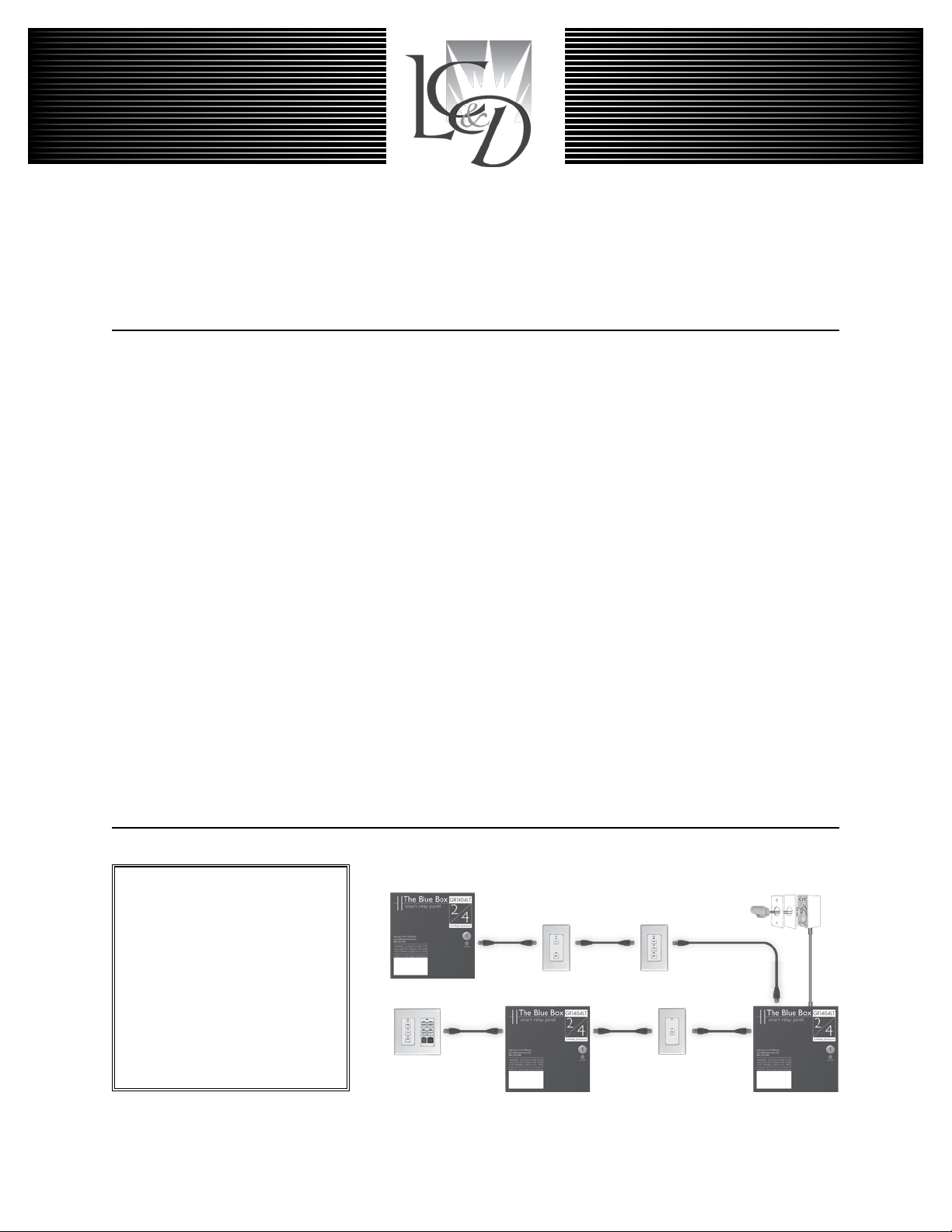
Digital Network:
Locate multiple Blue Box LTs and
control stations where you need
them and then link them all with
Cat. 5 cable. One master panel
(with a Digital Time Clock) for 16
digital devices. Control stations
LCDBBAND04Sept08
provide combined manual control
and after-hours override.
Note: The photocell is not on the
digital bus and should not be connected until Step 5.
(Refer to
Slave Relay Panel
Chelsea Digital Switch
Slave Relay Panel
STEP 5:
Verify proper connections and cabling for the entire bus using
the Hardware Activation Tests ......................Pg.42
STEP 6:
Make up low voltage cabling and connections for contact
closure devices and photocells. ... (See Installation Guides)
STEP 7:
Power-up and auto-address new devices.......... Pg.43
STEP 8:
Verify the system is operating without errors .....Pg.45-46
STEP 9:
Begin Programming..................(See O&M Manual)
Outdoor Photocell
Master Relay Panel
Page 40
40 THE BLUE BOX LT ADDING A NEW DEVICE
LOW vOLTAGE CABLING
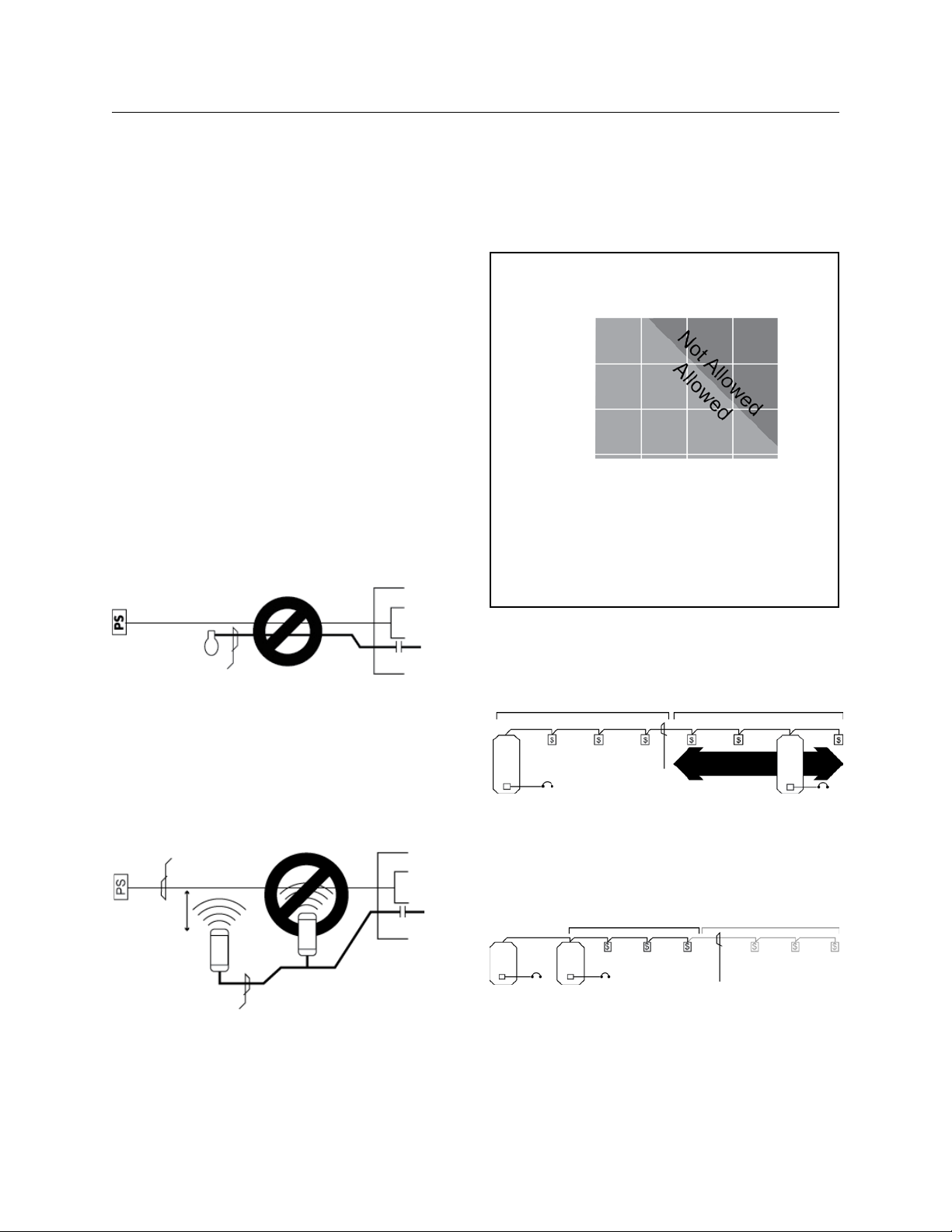
Digital devices have two RJ45 connectors and are daisychained using Cat. 5 (see cover). Non-digital devices (photosensors, toggle switches, etc.) are cabled per their installation guides (not daisy-chained).
Adhere to 568A or 568B standards for Cat. 5 cables.
!
Always use a dedicated pair for the center pins.
Refer to individual product installation guides for line-voltage cabling details and low voltage connection details Do
not “home run” digital switches back to a relay panel. No
spurs or T-Taps are allowed. Do not exceed 16 devices on
any system with a Blue Box LT Master.
ELIMINATE INTERFERENCE; ISOLATE CAT. 5
CABLES
…From Line Voltage Cable: Cat. 5 cable must be at least
12” from all line voltage conductors, except to cross or
make terminations.
Low Voltage Cable
Photosensor
Photosensor
Line Voltage Cable
Low voltage cabling must not be run in parallel with
line voltage cable, and must not share the same conduit,
whether digital cable (Cat. 5) or low voltage cable (3#18
from a photosensor).
…From Line Voltage Devices: Low voltage cabling must avoid
EMF or RF from ballasts, arc welders or other “noisy” loads.
EMF or RF interference can create an unstable bus.
Low Voltage
Cable
Photosensor
12" or more
Line Voltage Cable
Input
Relay
Relay Panel
Photosensor
Input
Relay
Relay Panel
DON’T CAUSE vOLTAGE DROP!
There is a limit to how many switches and photocell cards
you can add in a row over long runs of Cat. 5 cabling.
Bus-Powered Devices Allowed
for Each Active Device
1000 ft.
900 ft.
800 ft.
700 ft.
Total Feet of Cable from
One Active Device
Number of Bus-Powered Devices
Active Device - Device with power supply (a transformer). It
acts as a source of electrical energy for the bus.
Bus-Powered Device - Any device that relies on the 12v
supplied by the bus for its power. Example: digital switches,
and photosensor cards.
The more feet of Cat. 5 cable used, the fewer bus-powered devices before adding another active device.
Examples: Per the above char t, up to 3 bus-powered devices may be powered across 1,000 feet of Cat. 5 cable.
Bus-Powered Devices
Power
Active Device
The active device may be located anywhere within the
1,000 foot region.
Multiple active devices in the same location will not increase the distance allowed.
Power
Active Devices
For the above, the correct solution is to connect the active devices (relay panels) as the center of the network
and have two runs of cable. Call the Tech Support if cable
runs exceed 1000ft without active devices.
Bus-Powered Devices
3
6
9
12
Active Device Anywhere
Cat. 5 Cable
1000 ft. Insufficient Power
Power
in the 1000 ft. zone
Active Device
Bus-Powered Devices
Cat. 5 Cable
Power
LCDBBAND04Sept08
Page 41
THE BLUE BOX LT ADDING A NEW DEVICE 41
MAkING UP Rj45 CONNECTORS
Never made up RJ45 connectors before? Its easy. Just follow the steps below. For a shor t lesson on making RJ45
connectors, refer to The Blue Box LT “O&M Manual”.
To be successful, only use the ratcheting crimping tool recommended by LC&D and a Local Area Network (LAN)
cable tester that allows remote testing — the ends of the
cable will be remote from each other.
Only use stranded Cat. 5 cable.
!
Only use EZ RJ45 brand connectors provided by Light-
!
ing Control & Design (LC&D).
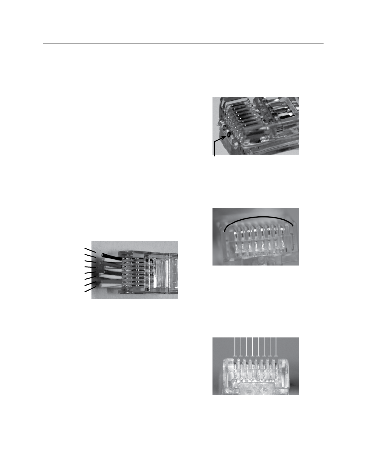
Remove two inches of the Cat. 5 jacket - use the 1.
wire stripper and cutter provided in our kit. Carefully
inspect the conductors for nicks.
Untwist all four pairs, and straighten/smooth out 2.
each conductor.
Reorganize the conductors in the order shown in the 3.
illustration below. Bring all conductors together until
they touch.
Contacts were not correctly cut off - will prevent
proper seating in socket.
Visually inspect each connector. Contacts should be 7.
pushed into the insulation of each conductor.
Repeat on the other end of the cable for a straight-8.
through cable.
Brown
Brown/White
Green
Blue/White
Blue
Green/White
Orange
Orange/White
Place an EZ connector on the end of the cable with 4.
the locking prong facing down.
Push conductors completely through and (using flush 5.
cutters or box cutters) trim-off all excess cable. Conductors should butt up to the end of the connector
– they must not protrude or be too short.
Always follow acceptable safety procedures when using a
!
sharp cutting tool. Tools
more hazards than sharp ones.
LCDBBAND04Sept08
Using the recommended ratcheting crimp tool, crimp 6.
at least five times for the best possible connection.
must be sharp; dull tools cause
Contacts not seated properly (bowed crimping).
Test every cable for continuity with a LAN cable tes-9.
ter. While testing, wiggle and tug on each connector
to test for a solid crimp.
Never make “hot” RJ45 crimps (crimping the other end of
a cable that has been plugged into a powered device). This
can damage equipment.
Contacts properly seated (at crimping).
Page 42
42 THE BLUE BOX LT ADDING A NEW DEVICE
HARDWARE ACTIvATION TESTS
Before starting, note total approximate bus cable length:
Once each cable has been checked with a LAN cable
tester and plugged-in, it is still possible for the entire connected cable structure to be problematic. For instance,
dirt may have accumulated inside the RJ45 sockets, the
strain on the Cat. 5 when pushing switches into the wall
may weaken connections or even break the conductors,
or the bus length may exceed 4000 ft.
Each test must be passed before moving onto the next. If
any readings are out of range, refer to “Hardware Activation Troubleshooting” section at the end of this document
or call Technical Support at 1-800-345-4448.
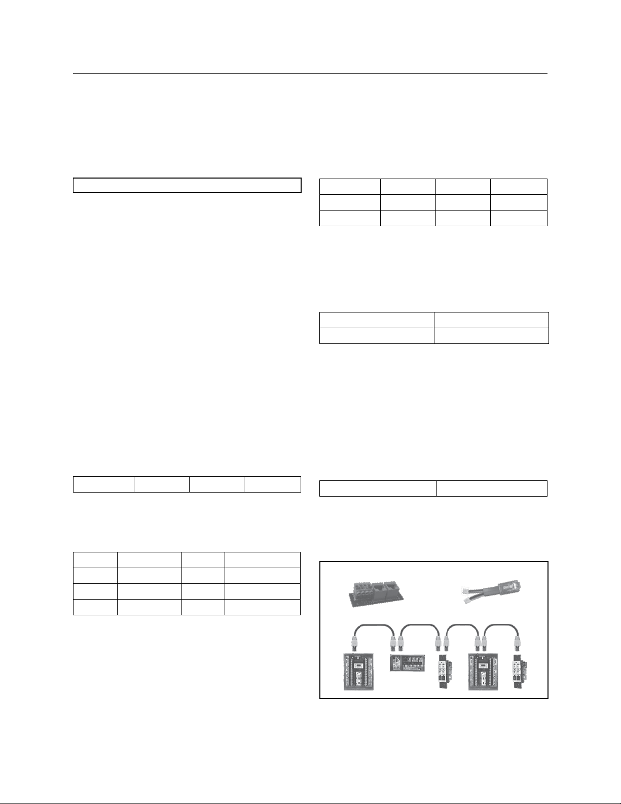
CONTINUITY TEST
This test is intended to verify bus length, continuity, and
detect crossed data-pair wires.
1. De-power every item on the bus and check the voltage
at both ends to ensure a reading of 0vdc. Remove any
terminators.
2. At one end of the bus, plug in the “Data/Power Jumper.”
3. At the other end of the bus, plug in the “Bus Checker Card”
and measure resistance across the following terminals:
Gnd to A ____ohms B to +12 ____ohms
6. All test values should be greater than 1K ohm!
Gnd to A ____ohms A to B ____ohms
Gnd to B ____ohms A to +12 ____ohms
Gnd to +12 ____ohms B to +12 ____ohms
EARTH GROUND TEST
This test is intended to detect any pathways to earth
ground.
7. Measure resistance between the terminals mentioned below, and “Earth ground” (a metallic enclosure or conduit).
Gnd A
+12 B
8. All readings between each terminal and “Ear th ground”
should be infinite or “Open”!
TERMINATOR TEST
This test is intended to ensure that only 2 terminators
exist, one at each end of the bus. If the readings are out of
range, it would indicate a missing, misplaced, or an extra
terminator.
9. Add a “Terminator” on the first and last device. On the
“Bus Checker Card“, measure
A to B ____ohms
4. All test values must be within 10% of the values in the
chart below to be considered valid!
Continuity Test Results (Gnd to A & B to +12)
Length Ohms Length Ohms
100 ft 3 Ω to 6 Ω 2000 ft 68 Ω to 80 Ω
500 ft 12 Ω to 20 Ω 3000 ft 102 Ω to 120 Ω
1000 ft 34 Ω to 40 Ω 4000 ft 130 Ω to 160 Ω
SHORT CIRCUIT TEST
This test is intended to detect any short circuits along the
bus. Please use the lowest resistance range (200 Ω) setting
on your multimeter. DO NOT use a “beep” test.
5. Remove the “Data Power Jumper.” On the “Bus Checker
Card,” measure the resistance across the following terminals:
10. Test reading should be within 62
11. Remove the bus checker card and call our Tech Support with your results at: 1-800-345-4448 x391.
Ω to 92 Ω!
Figure A:
Bus Checker Card
Data/Power Jumper
LCDBBAND04Sept08
Page 43
THE BLUE BOX LT ADDING A NEW DEVICE 43
Device Type
Location
Serial #
Address
Device Type
Location
Serial #
Address
Device Type
Location
Serial #
Address
Device Type
Location
Serial #
Address
Device Type
Location
Serial #
Address
Device Type
Location
Serial #
Address
Device Type
Location
Serial #
Address
Device Type
Location
Serial #
Address
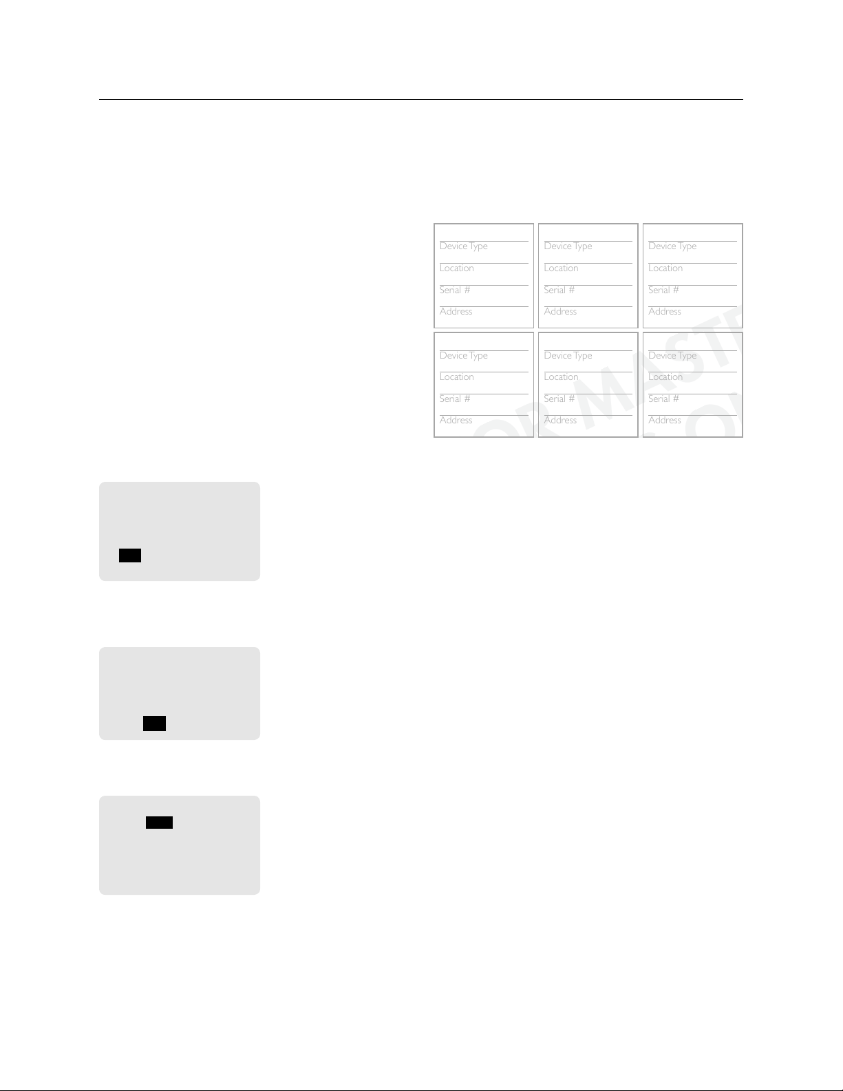
SYSTEM DEVICE SCHEDULE: (for Master Panels)
(Master) LCP1
1
3 btn sw
Hallway
8875
6 btn sw
lobby
4685
DI-6
LCP 1
4055
7
LCP 2
telecom
af97
5
(Master) LCP1
elec rm
ce80
1
AUTO-ASSIGNING ADDRESSES
TO A NEW DEvICE
Any newly added digital device (switch, relay panel, DI
card, etc) to any system with a Blue Box LT Master panels
may be auto-addressed as follows:
After completing the product Installation Guide(s), 1.
power up all Slave Panels, and active devices (any device with an onboard - 120 or 277 - power supply) first
and then power up the Master Panel. Check that the
power-indicator LEDs on all digital devices are lit-up.
The main screen will be displayed for a few seconds, 2.
after which the following will be displayed. TAB to YES
and press ENTER to auto-address the new device(s).
If the number of devices detected do not match the
number of devices present on the bus, proceed to
trouble-shooting section.
Found 1 device on the
system that are not used.
Would you like to
auto-assign them?
YES / NO / ->
Never Ask Again
To view address assignment, TAB to YES and press 3.
ENTER to go to the “Serial Number Scan” screen.
Assigned 1 device.
Review assignments by
scanning all serial
numbers?
YES / NO
If adding more than one device, TAB to “Serial#” field 4.
and SCROLL UP or DOWN to review each device.
SCAN by serial#
Serial# CE80
Adr: 6
Item Type: Switch
Mapd: 6 Btn. Switch
Address: OK
SAVE ADDRESS CHANGES
LCDBBAND04Sept08
Add the new device(s) to the “System Device Sched-5.
ule” on the back of the “Panel Schedule” located inside
the Blue Box LT Master Panel for future programming.
The “Serial Number
Scan” screen displays the
serial number, address,
and device-type of any
newly added device(s)
Not sure what the serial numbers are? Each device has a
unique Serial Number label or do the following to “read”
the Serial Number from the DTC clock:
a. Navigate to the “Read Address” screen: USER MENU
> SETUP MENU > RESTRICTED > ADDRESSINGBUS SCAN > READ ADDRESS. The password to
enter the RESTRICTED area is 900001.
b Press the first button on a switch or the “Address/
Assign” button. The screen will display the “Address”
and “Serial number”. Record this data on the System
Device Schedule.
ERROR CHECk
The system is now ready for Error Checking. EXIT repeatedly to navigate to the main menu.
Navigate to the Error Statistics Screen. Use the path 6.
USER MENU > SETUP MENU > RESTRICTED >
ADDRESSING-BUS SCAN > ERROR STATISTICS.
Tab to the field that says CLEAR and press ENTER to 7.
clear errors. If after 3 minutes no errors accumulate
on this screen, your system is stable.
If errors continue to accumulate, refer to the “Error 8.
Check Troubleshooting” section in the Blue Box LT
O&M Manual or System Start-Up and Cabling Guide
or call Technical Support: 1-800-345-4448.
Page 44
44 THE BLUE BOX LT ADDING A NEW DEVICE
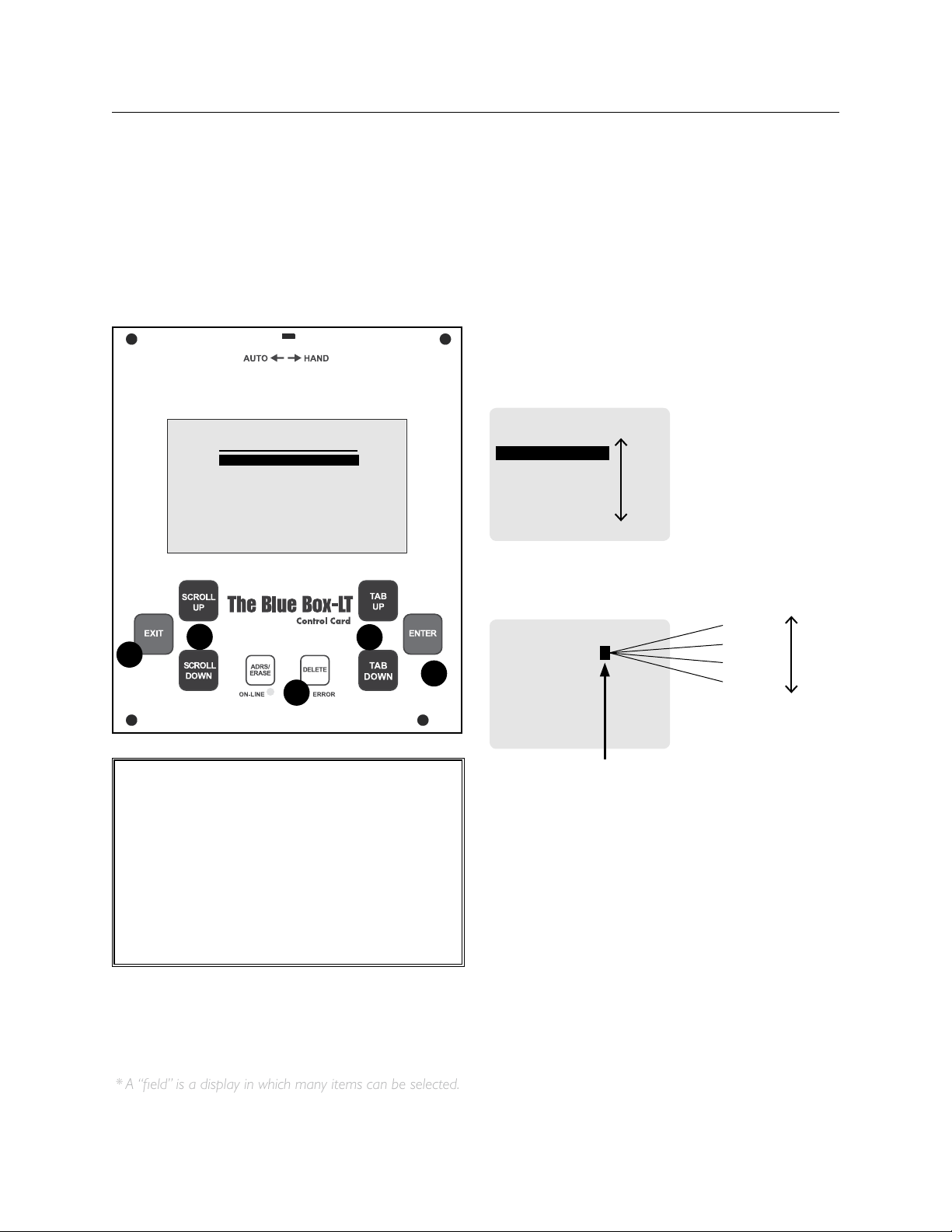
* A “field” is a display in which many items can be selected.
DTC CLOCk NAvIGATION BASICS
Most devices can be programmed from the DTC
(Digital Time Clock) in the master Lighting Control
Panel (LCP).
USER MENU
MANUAL OVERRIDE
REVIEW SCHEDULE
GROUP LOADS
PROGRAM SWITCH
SETUP MENU
1
3
4
5
2
CALL OUT LEGEND:
SCROLL through choices in one fi eld*1.
TAB to position the cursor2.
DELETE information or programming about 3.
an item. Use caution.
ENTER to select4.
EXIT to leave a screen.5.
TAB moves the cursor through a screen
SWITCHES PAGE 1-1
#04: SWITCH 4
#05: SWITCH 5
#06: SWITCH 6
#07: SWITCH 7
#08: SWITCH 8
#09: SWITCH 9
#10: SWITCH 10
SCROLL to choose one item from a fi eld.*
SWI ID05-5 TOGGLE
EDIT: LCP-2 LOAD-1
Load 4
Load 3
Load 2
Load 1
This“ eld” contains a list of possible
selections, but only displays one item
from that list at a time.
DIGITAL TIME CLOCk (DTC) NAvIGATION BASICS
DTC CLOCk NAvIGATION BASICS
All devices can be programmed from the DTC (Digital
Time Clock) in the master Lighting Control Panel (LCP).
TAB moves the cursor through a screen
SWITCHES PAGE 1-1
#04: SWITCH 4
#05: SWITCH 5
#06: SWITCH 6
#07: SWITCH 7
#08: SWITCH 8
#09: SWITCH 9
#10: SWITCH 10
SCROLL to choose one item from a field.*
SWI ID05-5 toggle
EDIT: LCP-2 LOAD-1
This“eld” contains a list of possible
selections, but only displays one item
from that list at a time.
Load 4
Load 3
Load 2
Load 1
LCDBBAND04Sept08
Page 45

THE BLUE BOX LT ADDING A NEW DEVICE 45
HARDWARE ACTIvATION TROUBLESHOOTING
Always re-check “failed” results. If improperly set or
!
connected a meter can display unusual readings during
testing.
The “Bus-Splitting Technique” is the fastest way to find
!
a bad cable and/or damaged device. Be sure to docu-
ment the cable path!
Cat. 5cables that pass a LAN cable test can still short
!
or break from stress and strain during installation. If retesting a suspected cable with a LAN tester, roughly wiggle
and tug the conductors (cable wires) near the RJ45 connector to ensure the conductors are properly engaged.
CONTINUITY TEST TROUBLESHOOTING
Fluctuating resistance readings indicate one or more 1.
“active” devices are still “hot”. De-power all devices
and re-test.
High resistance readings indicate broken or resistive 2.
connections. Use the “Bus-splitting” technique to find:
RJ45 connectors not properly pushed into sockets •
(check to make sure that the wires are not extended
beyond the end of the RJ45 connector)
•Cable strain can break conductors or pull conductors out of RJ45 contacts (visually inspect cable and
connector).
Unseated RJ45 sockets (rough install• environment)
Damaged device (rare)•
Dirt or paint on RJ45s (rare)•
Bad data/power jumper cable (rare)•
SHORT CIRCUIT TEST TROUBLESHOOTING
A low resistance reading indicates a crossed or short-1.
ed pair or (rarely) a damaged device. Cable strain
when pushing switches into a wall can short nicked
conductors. Use the bus splitting technique to find
the bad cable, crimp or device.
Resistance readings below 3002. Ω on A-B only indicate
an extra terminator. Use the bus splitting technique
LCDBBAND04Sept08
to find the short or extra terminator.
After the problem has been resolved, please com-3.
plete the “Continuity Test” again.
UNSTABLE BUS TROUBLESHOOTING
Ensure terminators are present at both ends of the bus.1.
EARTH GROUND TROUBLESHOOTING
LAN-tested cables can still have a path to earth ground.
An abraded or “folded” cable inside the conduit will 1.
cause a short to earth ground.
Other low voltage or high voltage wires touching 2 .
any device on the bus will cause continuity to ear th
ground
Use the Bus Splitting Technique to locate the problem.
TERMINATOR TROUBLE-SHOOTING
Ensure that the Data/Power Jumper is removed.1.
Visually inspect both terminators are present and 2.
properly seated on each bus-end device.
ERROR CHECk TROUBLESHOOTING:
If the hardware activation tests have just been completed
and the bus is unstable, consider the following causes:
Failure to follow the 568A or 568B color code (or 1.
minimally to use a dedicated pair for the center pins)
will cause the Error Check test to fail. Visually inspect
RJ45 connectors.
Occasionally the flat-cable connecting the clock to 2.
the Master panel can become damaged. Visually inspect the Cat. 5 cable – if damaged, replace it with a
new cable.
An external source of EMF (electro-magnetic fre-3.
quency) or RF (radio frequency) interference may
be affecting the bus (or digital devices). Refer to the
beginning of this guide on running low voltage cables
across or parallel to line voltage cables or exposing
low voltage cables to EMF or RF sources (e.g. welders,
ballasts, improperly grounded wireless devices, etc.);
any of which can interfere with the bus operation
and stability.
Visually inspect and handle any external sources of signal
noise - a digital device can also become damaged and create signal noise.
An oscilloscope can be used to locate the source of the
bus failure. The Oscilloscope Test procedures can be found
in The Blue Box LT “O&M Manual”. If unfamiliar with how
to use an oscilloscope or if one is unavailable on-site, contact Tech Support: 1-800-345-4448.
Page 46
HARDWARE ACTIvATION TROUBLESHOOTING
(Continued)
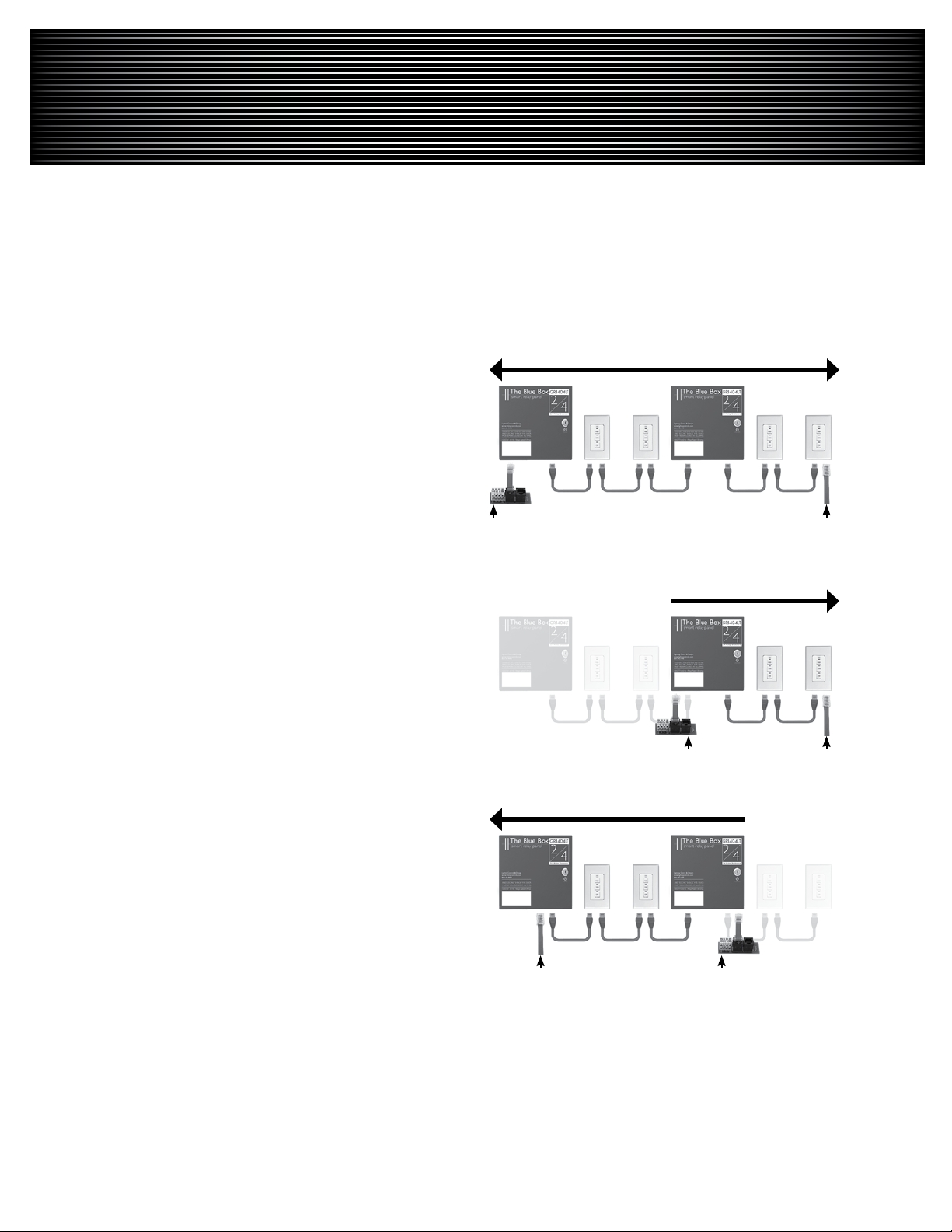
BUS SPLITTING TECHNIqUE
Note:To speed up troubleshooting when readings are
!
less than 200Ω on the Continuity or Short-Circuit test,
refer to the “Bus Length Chart” earlier in this document
before splitting the bus; this can provide an approximate
distance to a shorted pair or extra terminator from the
test point.
On the middle device of the bus, disconnect one Cat. 1.
5 cable to create two smaller “half-buses”.
Test each “half-bus” to find the side with the out-of-2.
range values.
Repeat steps 1 & 2 on the out-of-range “half-bus,” 3.
to create another “half-bus” until the cable, crimp or
device creating the out of range measurements is located.
The idea is to split a bus in half and then half again – over and
over until the bad area has been located. It is OK to visually
inspect each cable, crimp or device to detect the problem.
Bus Checker Card Data/Power Jumper
Bus Checker Card Data/Power Jumper
Bus Checker CardData/Power Jumper
LIGHTING CONTROL & DESIGN
905 Allen Ave • Glendale, CA 91201 • Support 800-345-4448 • www.lightingcontrols.com
LCDBBAND04Sept08
Page 47

®
THE BLUE BOX™ LT
PARTS REPLACEMENT &
INSTALLATION GUIdE
LCDBBPRIG03Sept08
®
Lighting Control & Design
905 Allen Ave, Glendale CA 91201
•
Tel: 800-345-4448
www.lightingcontrols.com
Page 48
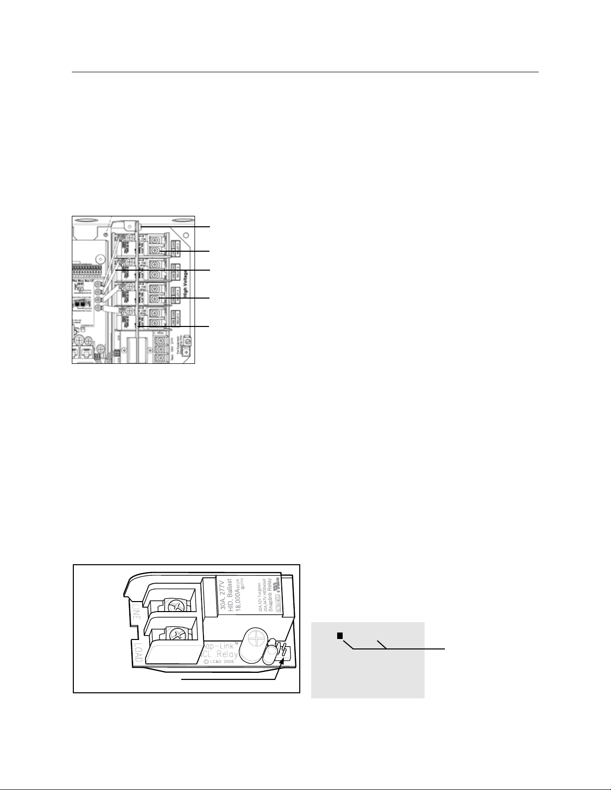
48 THE BLUE BOX LT PARTS REPLACEMENT & INSTALLATION GUIDE
LC&D recommends that any suspect circuit be faultchecked prior to re-energizing.
RELAY REPLACEMENT AND INSTALLATION
Screw/ Lockwasher
fasteners
Relays
Low Voltage jumper
connector
Line/Load Connection
lugs
line/low voltage
barrier
To remove a defective relay:
Switch off all breakers feeding relays and the 1.
transformer in the Blue Box LT.
For master panels: Unscrew and open the hinged 2 .
display-panel door to expose the high-volatge section.
Remove the screw and lockwasher fasteners that 3.
hold the line/low voltage barrier over the relays.
Pull off the low voltage jumper that connects the relay to 4.
the control card (LT 4 & 8) or the smacker strip (LT 16).
Loosen the LINE and LOAD connection lugs on 5.
the relay and remove the conductors. [Note: For
safety reasons, use a wire nut to tie the two wires
together]
Line Lug
Removal Slot
Load Log
Low voltage connector pins
Pry the relay out of the plastic track by applying a 6.
flat-blade screw driver to the slot located at the
relay card’s edge near the line and load lugs.
To replace a defective relay
Push the replacement relay back into the track 7.
until it “snaps” securely in place – use a flat-blade
screw driver to snap in one or both ends.
Reconnect the low voltage jumper between the 8.
relay and the relay driver pins on the control card
(LT4 and LT8) or the smacker strip (LT16).
Re-install the line/low voltage barrier and the screw 9.
and lockwasher fasteners. If necessary, break out
the “break-away“ tab(s) (one for each new relay)
on the voltage barrier for the replacement relay(s).
Reconnect Line and Load conductors to the 10.
connection lugs.
For master panels: Close and screw down the 11.
hinged display-panel door.
After the defective par t replacement installation 12.
is complete, return the part using the prepaid
USP return label and envelope to LC&D.
[Note: If the defective part is not returned within a
30-day period, your account will be automatically billed
for the part. ]
To exercise and test the replacement relay:
Switch the breakers powering all the relays and 13.
the transformer back ON
Navigate on the DTC to USER MENU > 14.
MANUAL OVERRIDE and TAB or SCROLL to
the correct LCP and Load (relay) and ENTER to
exercise the relay by switching it on and off 3 or 4
times. If possible, listen to hear the relay contacts
clicking as they open and close.
MANUAL CONTROL AU
LCP-1 LOAD-1
1- 3■ 5■ 7■ 9- 11- 13- 15-
2- 4- 6- 8■ 10- 12- 14- 16-
SCROLL to select LCP
TAB to LOAD
SCROLL to select
LOAD
ENTER to toggle
status
LCDBBPRIG03Sept08
Page 49
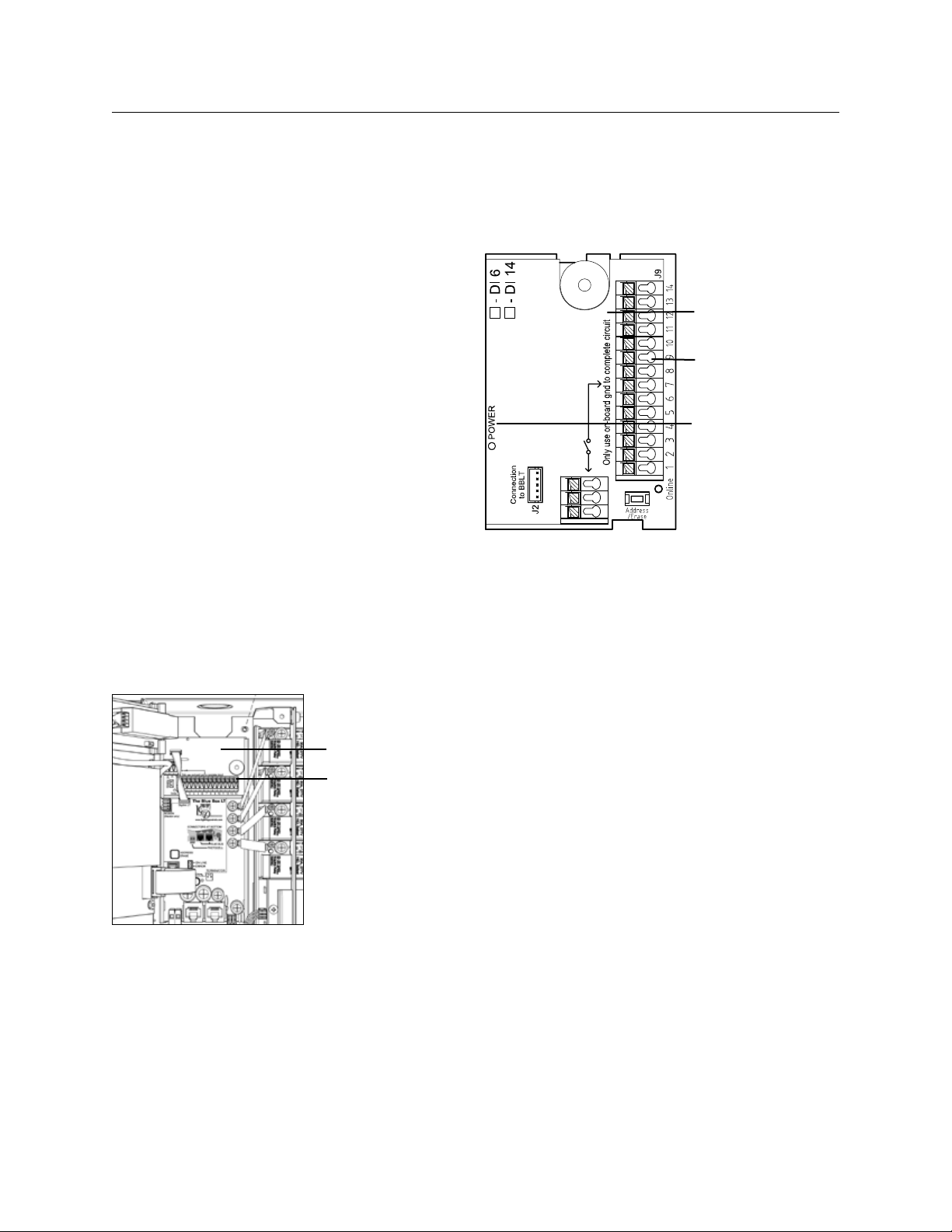
THE BLUE BOX LT PARTS REPLACEMENT & INSTALLATION GUIDE 49
24V 3.3V Gnd
Refer to the Digital Input Card Installation Guide
section of the Blue Box LT “O&M Manual” for more
details.
DI CARD REPLACEMENT AND INSTALLATION
To remove a defective DI Card:
Note the address of the existing DI Card. Refer to 1.
the SYSTEM DEVICE SCHEDULE in the master
panel or by process of elimination - the READ
ADDRESS screen.
De-power the Blue Box LT by switching off the 2.
breaker feeding the power supply (the relays in
that panel will close).
Disconnect the power/data jumper cable from 3.
the DI card (leave it connected to the control
card).
Remove all low voltage conductors for contact 4.
closure devices from the input/output terminals.
Pry the DI Card out of the plastic track by 5.
applying a flat-blade screw driver to the slot on
the side of the card.
DI Card
Input/output
terminals
To replace a defective DI Card
Snap the new DI card into the plastic track .6.
Re-connect the power/data jumper cable to the 7.
DI card.
Reconnect all low voltage conductors for contact 8.
closure devices to the input/output terminals.
Re-power the Blue Box LT.9.
If this is a master panel, the main screen will 10.
be displayed for a few seconds, after which the
“device detection” screen will be displayed. DO
NOT ASSIGN THIS DEVICE A NEW ADDRESS!
TAB to NO and ENTER
When the screen prompts: ”Are you sure?” TAB 11.
to YES and ENTER.
After the defective par t replacement installation 12.
is complete, return the part using the prepaid
USP return label and envelope to LC&D.
DI Card
Input/output
terminals
Power
LCDBBPRIG03Sept08
[Note: If the defective part is not returned within a
30-day period, your account will be automatically billed
for the part. ]
To address the replacement DI Card
Navigate to the AUTO-ADDRESSING screen: 13.
USER MENU> SETUP MENU> RESTRICTED
(PASSCODE: 900001) > ADDRESSING-BUS
SCAN > AUTO ADDRESSING.
Page 50
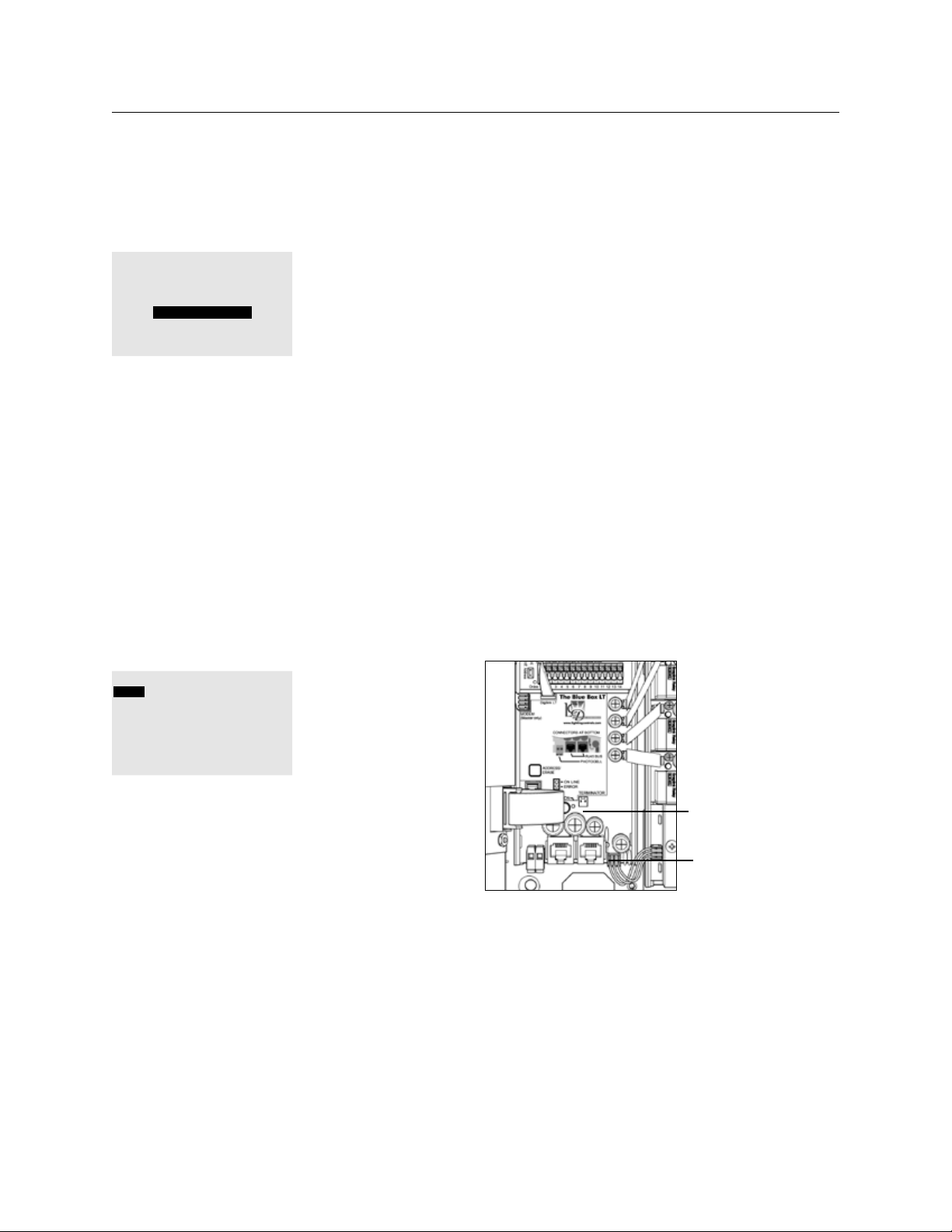
50 THE BLUE BOX LT PARTS REPLACEMENT & INSTALLATION GUIDE
DEVICE MANAGEMENT
SCAN BY SERIAL #
ERASE ALL ADDRESSING
AUTO ADDRESSING
SCAN FOR ZERO ID ON
POWER UP: YES
SCROLL UP until the address of the previous DI 14.
is displayed.
Press the address button on the DI CARD. 15.
If the DI “takes” the address, the display will 16.
increment by one (e.g. from “3” to “4”).
To verify the bus recognizes the replacement DI
Card:
Navigate to SCAN BY SERIAL NUMBER screen: 17.
USER MENU > SETUP MENU > RESTRICTED
(PASSCODE 900001) > ADDRESSING –
BUS SCAN> BUS DIAGNOSTICS > MORE
DIAGNOSTICS > DEVICE MANAGEMENT >
SCAN BY SERIAL#
SERIAL# SCAN
BACK FWD |SAVE|
SERIAL# CE80
ADR: 1
LCP
NO ADDRESS COLLISION FOUND
ON THIS CARD
that panel will close).
Once the panel is de-powered, disconnect all 2.
cables connected to the control card.
Pry the Control Card out of the plastic track by 3.
applying a flat-blade screw driver to the slot on
the side of the card.
To replace a defective Control Card
Snap the new control card into the plastic track.4.
Re-connect all cables and conductors to the 5.
control card.
Re-power the Blue Box LT6.
After the defective par t replacement installation 7.
is complete, return the part using the prepaid
USP return label and envelope to LC&D.
[Note: If the defective part is not returned within a
30-day period, your account will be automatically billed
for the part. ]
ENTER to begin a system scan.18.
If the screen shows no collisions, DI Card 19.
replacement is complete.
If collisions exist, contact Technical Support.20.
Reconnect all low voltage conductors for contact 21.
closure devices to the low voltage input/output
terminals.
Program the new DI card.22.
CONTROL CARD [MASTER] REPLACEMENT AND
INSTALLATION
To remove a defective Control Card
De-power the Blue Box LT by switching off the 1.
breaker feeding the power supply (the relays in
Master Control Card
Power
LCDBBPRIG03Sept08
Page 51
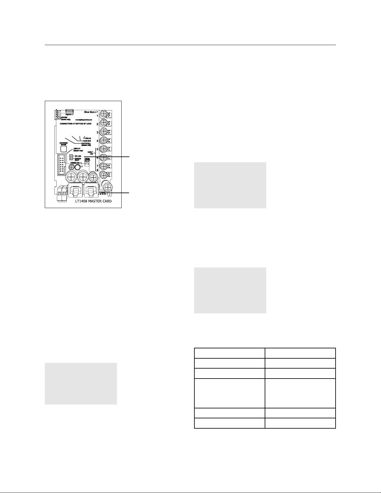
THE BLUE BOX LT PARTS REPLACEMENT & INSTALLATION GUIDE 51
If collisions exist, contact Technical Support.11.
If no collisions exist or collisions have been 12.
resolved, the bus needs to be mapped so that
the devices can be programmed. Navigate to
the BUS MAP screen: USER MENU > SETUP
MENU > RESTRICTED (PASSCODE 900001) >
Master Control Card
Power
ADDRESSING – BUS SCAN> BUS MAP.
ADDRESSING PAGE 1-19
ID1 : UNUSED
ID2 : UNUSED
ID3 : UNUSED
ID4 : UNUSED
ID5 : UNUSED
ID6 : UNUSED
ID7 : UNUSED
To address and verify the bus recognizes replacement Control Card
The Blue Box master Control Card contains the time
clock for the system. To save time, the time, date and
location settings can be pre-loaded at the factory - if
requested. Time schedules and any groups which had
Loads (relays) in LCP 1 (master panel) will need to be
re-programmed.
If your system has a modem, contact Technical Support
to have all of the programming (listed below) done.
Navigate to SCAN BY SERIAL NUMBER screen: 8.
USER MENU > SET UP MENU > RESTRICTED
(PASSCODE 900001) > ADDRESSING –
BUS SCAN> BUS DIAGNOSTICS > MORE
DIAGNOSTICS > DEVICE MANAGEMENT >
SCAN BY SERIAL#
ENTER to begin a system scan.9.
SCAN BY SERIAL#
SCANNING COMPLETE.
FOUND 3 ITEMS.
NOT ADDRESSED: 0
HIT ENTER WHEN READY
LCDBBPRIG03Sept08
If the Screen shows no collisions SCROLL through 10.
each device noting down the address (ID) and
the device type (3 button switch, etc)
To define the Master Blue Box, TAB to ID1 and 13.
SCROLL to select Panel LCP 1 (4 or 8 relay
panels). For a 16 relay panel, TAB to ID2 and
SCROLL to “Panel LCP 1” also. Every 8 relays
take up an address, so a 16 relay panel will take
up 2 addresses.
ADDRESSING PAGE 2-19
ID1 : PANEL LCP1
ID2 : PANEL LCP1
ID3 : UNUSED
ID4 : UNUSED
ID5 : UNUSED
ID6 : UNUSED
ID7 : UNUSED
Map the remaining devices into the BUS MAP 14.
screen using the data from the SCAN BY SERIAL
NUMBER screen
Item Bus Map Name
Blue Box LT-4 Panel LCP X (1-32)
Blue Box LT-8 Panel LCP Y (1-32)
Blue Box LT-16
(Blue Box LT 16 requires
Panel LCP Z (1-32)
Panel LCP Z (1-32)
two addresses)
1 button digital switch 1 Btn. Switch, etc
DI-14 14 Btn. Switch
Page 52
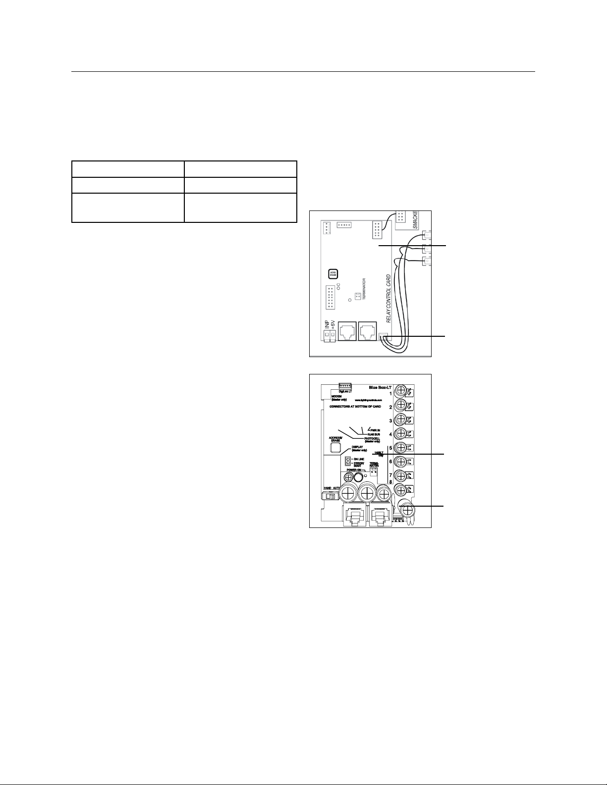
52 THE BLUE BOX LT PARTS REPLACEMENT & INSTALLATION GUIDE
Item Bus Map Name
DI-6 14 Btn. Switch
Any Digital Switch that is
14 Btn. Switch
enabled or disabled
Re-program schedules and groups
Since the master panel control card is also 15.
the system clock, all programs will need to be
programmed back into the clock.
Any groups which had relays in LCP 1 will need 16.
to be modified to add back the relays from LCP 1.
Relays from other LCPs will automatically appear
on the Groups screens.
CONTROL CARD [SLAvE] REPLACEMENT AND
INSTALLATION
To remove a defective Control Card
Note the address of the LCP (lighting control 1.
panel). Refer to the SYSTEM DEVICE SCHEDULE
in the Master Panel or use the READ ADDRESS
screen.
De-power the Blue Box LT by switching off the 2.
breaker feeding the power supply (the relays in
that panel will close).
Once the panel is de-powered, disconnect all 3.
cables connected to the control card.
Pry the Control Card out of the plastic track by 4.
applying a flat-blade screw driver to the slot on
the side of the card. [Note: If this is a warranty
replacement, do not forget to ship relay back to
LC&D.]
To replace a defective Control Card
Snap the new control card into the plastic track.5.
Re-connect all cables and conductors to the 6.
Control Card.
Re-power the Blue Box LT.7.
After the defective par t replacement installation 8.
is complete, return the part using the prepaid
USP return label and envelope to LC&D.
[Note: If the defective part is not returned within a
30-day period, your account will be automatically billed
for the part. ]
Slave Control Card
Power
Slave Control Card
Power
To address and verify the bus recognizes replacement Control Card
Navigate to the AUTO ADDRESS screen: 9.
USER MENU> SET UP MENU> RESTRICTED
(PASSCODE: 900001) > ADDRESSING BUS
SCAN > AUTO ADDRESSING.
SCROLL UP until the address of the LCP is 10.
displayed.
Press the address button on the Control Card. 11.
If the address “takes” the address on the display 12.
will increase by one for an LT4 and LT-8, or 2 for
an LT-16) (e.g. from “3” to “4”).
LCDBBPRIG03Sept08
Page 53
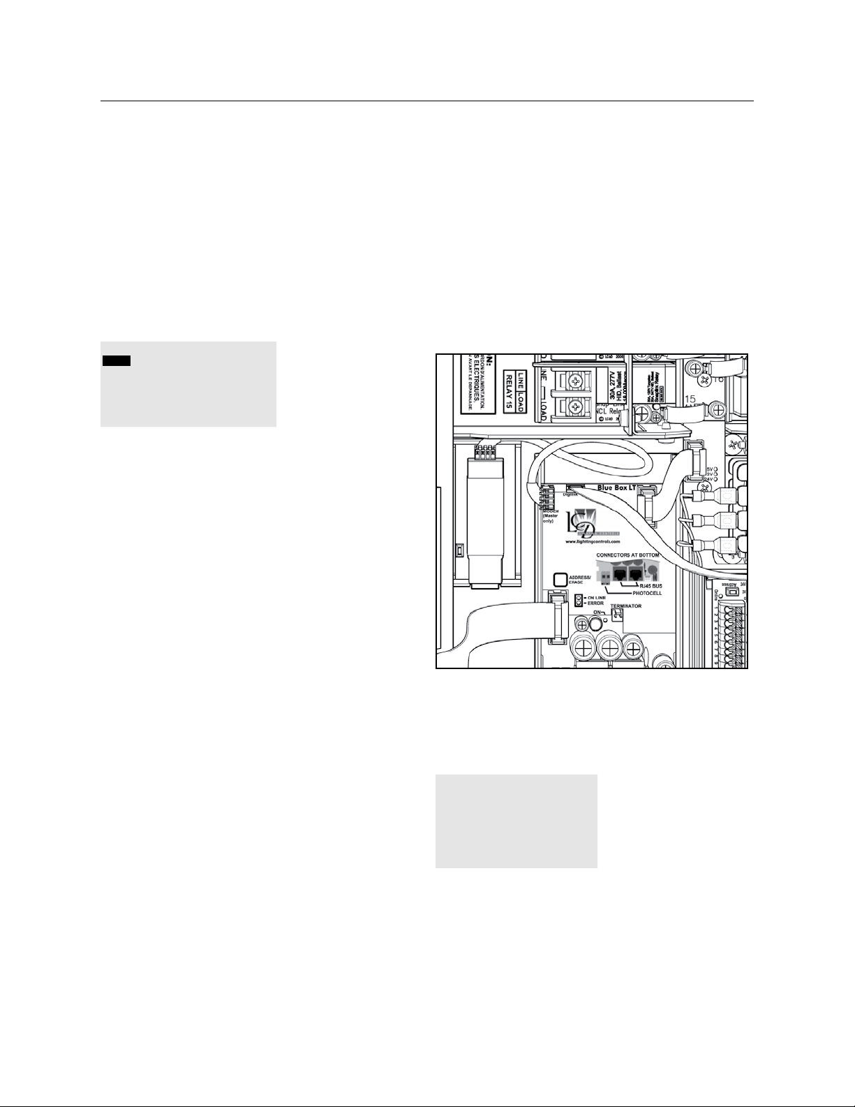
THE BLUE BOX LT PARTS REPLACEMENT & INSTALLATION GUIDE 53
Navigate to SCAN BY SERIAL NUMBER screen: 13.
USER MENU > SETUP MENU > RESTRICTED
(PASSCODE 900001) > ADDRESSING –
BUS SCAN> BUS DIAGNOSTICS > MORE
DIAGNOSTICS > DEVICE MANAGEMENT >
SCAN BY SERIAL#
SERIAL# SCAN
BACK FWD |SAVE|
SERIAL# CE80
ADR: 1
LCP1
NO ADDRESS COLLISION FOUND ON
THIS CARD
ENTER to begin a system scan.14.
If collisions exist, contact Technical Support.15.
If no collisions exist or collisions have been 16.
resolved, the bus needs to be mapped so that
the devices can be programmed. Navigate to
the BUS MAP screen: USER MENU > SETUP
MENU > RESTRICTED (PASSCODE 900001) >
ADDRESSING – BUS SCAN> BUS MAP.
Re-program Groups
Any Groups which had relays in the LCP with the 17.
new control card will need to be modified to add
back the relays from that LCP. Relays from other
LCPs remain unaffected.
REPLACING A MODEM (MASTER PANELS ONLY)
To remove a defective modem
Disconnect the power/data cable connected to 1.
the modem.
Disconnect the RJ-12 (phone line)2.
Pry the modem out of the plastic track by applying 3.
a flat-blade screw driver to the slot located on
the side of the card.
After the defective par t replacement installation 7.
is complete, return the part using the prepaid
USP return label and envelope to LC&D.
[Note: If the defective part is not returned within a
30-day period, your account will be automatically billed
for the part. ]
Modem
To verify replacement modem is operational:
Navigate to the DIAL UP HOST screen: USER 8.
MENU > SETUP MENU > RESTRICTED
(PASSCODE 900001) > REMOTE SYSTEM
MENU > DIAL UP HOST
DIALING UP HOST
ENTER THE COMPLETE
PHONE NUMBER OF THE
HOST AND HIT ENTER.
To replace a defective Modem
LCDBBPRIG03Sept08
Snap the new modem into the plastic track .4.
Re-connect cables. 5.
Re-power the Blue Box LT6.
Refer to the DIAL UP HOST section in the O&M 9.
manual to place an outbound call to a cell phone
or land line.
A successful call means installation is complete. 10.
If the call was not successful, contact Technical
Support for assistance.
Page 54
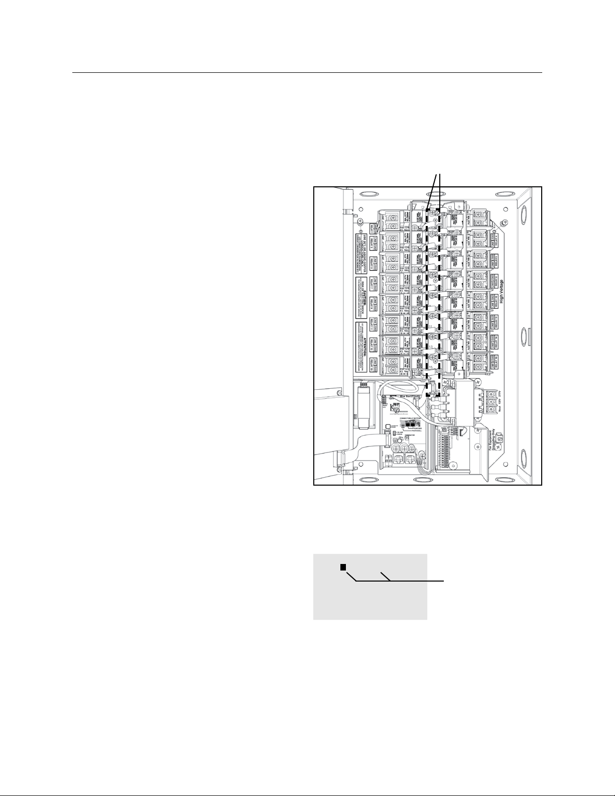
54 THE BLUE BOX LT PARTS REPLACEMENT & INSTALLATION GUIDE
DTC DISPLAY REPLACEMENT AND
INSTALLATION
Unplug the jumper cable at the back of the 1.
DTC.
Unscrew the four fasteners on the back of the 2.
DTC.
Mount the new DTC.3.
Re-connect the new DTC.4.
After the defective par t replacement installation 5.
is complete, return the part using the prepaid
USP return label and envelope to LC&D.
[Note: If the defective part is not returned within a
30-day period, your account will be automatically billed
for the part. ]
SMACkER STRIP (BLUE BOX LT16)
REPLACEMENT AND INSTALLATION
To remove a defective smacker strip
De-power the Blue Box LT by switching off the 1.
breaker feeding the power supply (the relays in
that panel will close).
Once the panel is de-powered, disconnect all 2.
cables connected to the smacker strip.
Remove the three screws and lift the smacker 3.
strip out of the panel.
To replace a defective smacker strip
Mount the new Smacker Strip using the three 4.
screws.
Re-connect all flat cables and relay jumpers. 5.
Refer to the Blue Box LT 16 schematic drawing if
uncertain about cable placement.
Re-power the Blue Box LT.6.
After the defective par t replacement installation 7.
is complete, return the part using the prepaid
USP return label and envelope to LC&D.
[Note: If the defective part is not returned within a
30-day period, your account will be automatically billed
for the part. ]
Smacker Strip
To verify proper connections:
To exercise and test the newly added smacker 8.
strip, navigate to the MANUAL OVERRIDE
screen: USER MENU > MANUAL OVERRIDE
MANUAL CONTROL AU
LCP-1 LOAD-1
1- 3■ 5■ 7■ 9- 11- 13- 15-
2- 4- 6- 8■ 10- 12- 14- 16-
SCROLL to select LCP
TAB to LOAD
SCROLL to select
LOAD
ENTER to toggle status
TAB or SCROLL to the correct LCP. Exercise each 9.
relay by manually switching it on and off 3 or 4
times. Make sure the relay corresponds to the Load
number on the MANUAL OVERRIDE screen.
Correct any mis-connections.10.
LCDBBPRIG03Sept08
Page 55
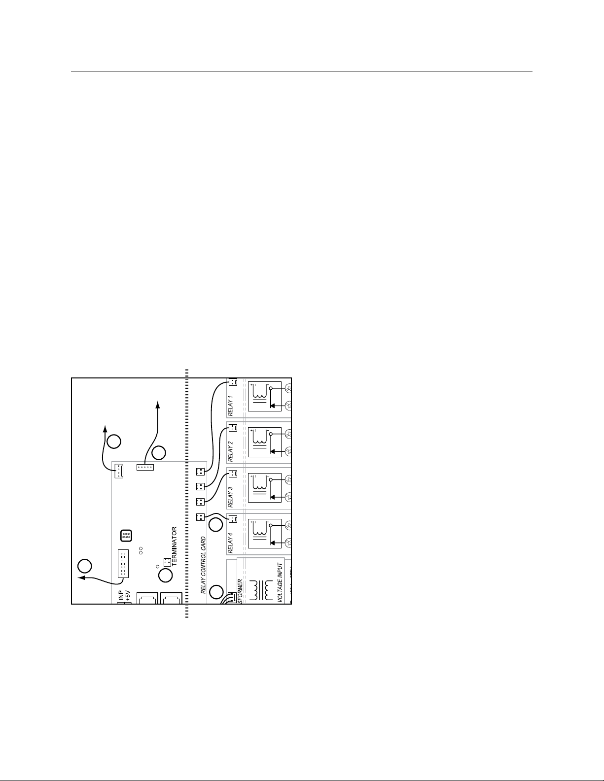
THE BLUE BOX LT PARTS REPLACEMENT & INSTALLATION GUIDE 55
To DTC
To optional Modem
master panels only
To optional DI Card
3
4
5
6
1
2
TRANSFORMER REPLACEMENT AND
INSTALLATION
To remove a defective Transformer
De-power the Blue Box LT by switching off the 1.
breaker feeding the power supply (the relays
in that panel will close). De-power any other
breakers that may present a hazard during
installation.
For master panels: Unscrew and open the hinged 2.
display-panel door to expose the high-voltage
section.
Remove the screw and lockwasher fasteners 3.
that hold the line/low voltage barrier on top of
the power supply (transformer) and remove the
barrier to free it up.
Low Voltage/High Voltage Barrier
For LT 4 and 8: Pr y the transformer out of the 6.
plastic track by applying a flat-blade screw driver
to the slot located at the card’s edge near the
hot and neutral lugs. For LT 16: Remove the four
screws at the base of the transformer.
To replace a defective Transformer
For LT 4 and 8: Push the new replacement 7.
transformer into the track until it “snaps” securely
in place. You may need to use a flat-blade
screw driver to snap in one or both ends. For
LT 16: Mount the new transformer with the four
screws.
Reconnect the low voltage connectors.8.
Reconnect hot and neutral conductors9.
Re-install the line/low voltage barrier and the 10.
screw and lockwasher fasteners.
For master panels: Close and screw down the 11.
hinged display -panel door.
Re-power any breakers.12.
After the defective par t replacement installation 13.
is complete, return the part using the prepaid
USP return label and envelope to LC&D.
LCDBBPRIG03Sept08
Low Voltage High Voltage
Loosen the hot and neutral connection lugs on the trans-4.
former’s terminal block and remove the conductors.
Pull off the low voltage connector(s) (one wire 5.
for LT 4 and 8 and three wires for LT 16) that
connects the transformer to the control card.
[Note: If the defective part is not returned within a
30-day period, your account will be automatically billed
for the part. ]
To exercise the replacement Transformer
Visually inspect that the ONLINE LED on the 14.
control card is blinking and the clock is powered
up and displaying correctly.
Navigate on the DTC to USER MENU > 15.
MANUAL OVERRIDE and TAB or SCROLL to
the correct LCP and Load (relay). Exercise each
relay by manually switching it on and off 3 or 4
times. If possible, listen to hear the relay contacts
clicking as they open and close.
Page 56
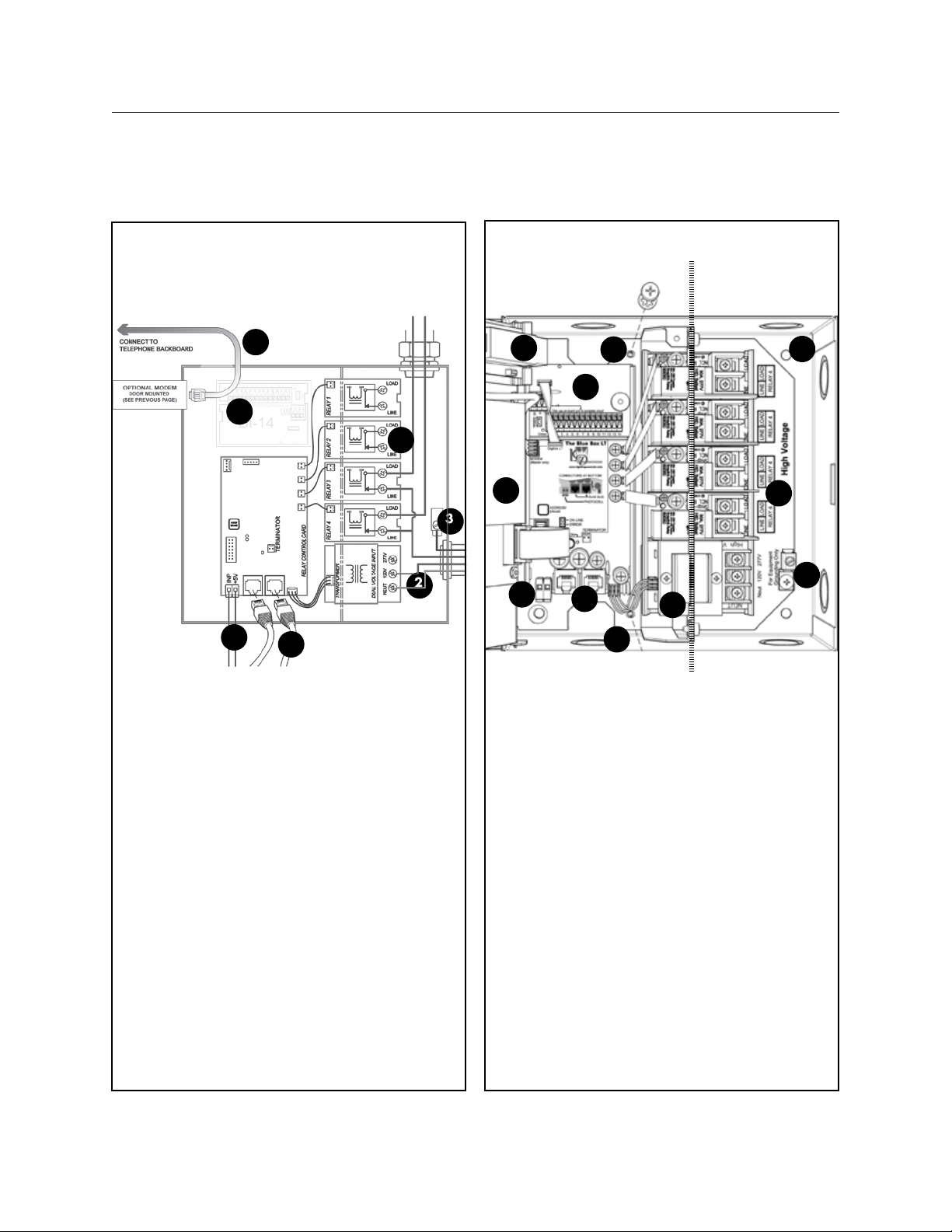
56 THE BLUE BOX LT PARTS REPLACEMENT & INSTALLATION GUIDE
BLUE BOX LT 1404/1408
low voltage only line voltage only
7
6
1
3
2
4
5
10
5
4
2
8
3
2
9
1
6
7
3#18 AWG. Supplies power and neu-1.
tral from transformer to relay control
card.
1-14 conductor ribbon cable: carries
2.
control signal between DTC and relay
control card (master panel only).
4(1404LT)/ 8 (1408) 2 conductor rib-
3.
bon cable: carries control signal from
smacker strip to relays - one per relay.
Terminator / terminator pin-outs. (pro-
4.
vided inside master panel) - terminates
bus line.
Blue Box mounting holes (4).1.
Back plate mounting screws.2.
RJ45 sockets for GR 2400 bus.3.
Photocell input (master only). The Pho-4.
tocell may control any relay(s) in any
panel(s).
Optional modem. Analog phone line con-
5 .
nects to RJ-12 socket.
Relays (line and load lugs).
6.
Dual-voltage (120V or 277V)power 7.
supply.
(Optional) Digital Input Card. [DI] 14
8.
(or 6 enable/disable) inputs.
Terminator pins. Terminate the bus only
9.
after the “System Start-Up and Cabling
Guide” has been completed.
Clock backplate and back of DTC clock
10.
(for the master panel only).
LCDBBPRIG03Sept08
Page 57
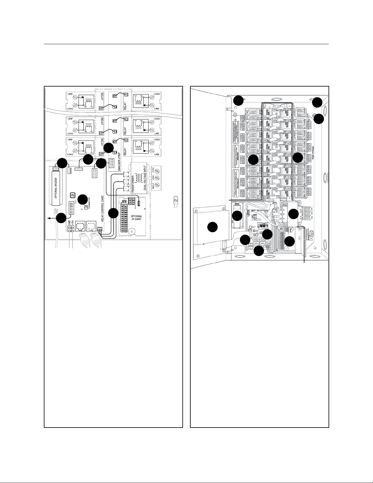
THE BLUE BOX LT PARTS REPLACEMENT & INSTALLATION GUIDE 57
BLUE BOX LT 1416
6
2
3#18 AWG. Supplies power and neu-1.
tral from transformer to relay control
card.
14 conductor ribbon cable: carries
2.
control signal between DTC and relay
control card (master panel only).
2 conductor ribbon cable: carries con-
3.
trol signal from smacker strip to relays
- one per relay.
P10 conductor ribbon cable: carries
4.
digital signal from relay control card to
smacker strip
5 conductor ribbon cable: carries digital
5.
signal from relay control card to (optional) digital input card
4#22AWG carries rs-232 signal from
6.
(optional) modem to relay control card
(master panel only) Dual-voltage (120V
LCDBBPRIG03Sept08
or 277V)power supply.
Terminator / terminator pin-outs. (pro-
7.
vided inside master panel) - terminates
bus line.
2
3
5
4
7
1
10
6
5
9
4
3
6
7
8
1
2
Blue Box mounting holes (4).1.
Back plate mounting screws. (Retaining 2.
pin located at bottom, lift up and out to
remove)
RJ45 sockets for GR 2400 bus.
3.
Photocell input (master only). The Pho-4.
tocell may control any relay(s) in any
panel(s).
Optional modem. Analog phone line con-
5 .
nects to RJ-12 socket.
Relays (line and load lugs).
6.
Dual-voltage (120V or 277V)power 7.
supply.
(Optional) Digital Input Card. [DI] 14
8.
(or 6 enable/disable) inputs.
Terminator pins. Terminate the bus only
9.
after the “System Start-Up and Cabling
Guide” has been completed.
Clock backplate and back of DTC clock
10.
(for the master panel only).
Page 58

LCDBBPRIG03Sept08
Page 59

™
®
BLUE BOX
LT
HARdWARE
TROUBLESHOOTING
LCDBBHTS03Sept08
®
Lighting Control & Design
905 Allen Ave, Glendale CA 91201
Tel: 800-345-4448 • www.lightingcontrols.com
Page 60

60 THE BLUE BOX LT HARDWARE TROUBLESHOOTING
HARDWARE TROUBLESHOOTING
RELAY TROUBLESHOOTING
This section contains the most common problems, causes
and solutions for troubleshooting relays. These specific
issues will be covered in depth:
Relay(s) stuck open / stuck closed•
Light turns OFF by itself after a certain period of time•
Light turns ON by itself after a certain period of time•
Relay(s) chattering•
PROBLEM: Relay(s) not working:
Relay may be stuck to its previous state and need to be cycled
Go to “Manual Override” screen•
Try to cycle the relay ON/OFF•
If successful, the physical relay status and the on-•
screen status indicator will change, in addition the
relay should start clicking
QUESTION:
Is the relay “Stuck Open”?
Stuck Open – Lights are constantly OFF, no continuity
across the relay when you measure across line & load, and
no voltage going to the load side of the relay
Check the circuit breaker:a)
Verify the breaker is set to the ON position•
If necessary, measure voltage on Line Side of relay.•
Next, find out what type of relay it is:b)
“Normally Open Relay”•
“Normally Closed Relay”•
If the relay is “Stuck Open” and it is a Normally c)
Closed Relay (relays are defaulted to the “Normally Closed” position):
Unplug the relay jumper to cut the power of the •
relay and it should go to its failed state
The relay is “Normally Closed” so it should fail closed•
The red LED on the relay should be OFF•
There should be continuity if you measured across •
the relay. There should be voltage going to the
load side
Is the relay “Stuck Closed”?
Stuck Closed – Lights are constantly ON, there’s continuity
across the relay when you measure across line & load, and
there’s voltage (120/277) going to the load side of the relay
If the relay is “Stuck Closed” and it is a Normally a)
Open Relay:
Unplug the relay jumper to cut the power to the •
relay; if the relay is “Normally Open” it should go
to its fail state, it should fail open.
The red LED on the relay should be OFF, if not•
Troubleshooting to check:
...If the relay is bad:
Swap relay with a known working relay or use a spare•
Then cycle the relay ON & OFF•
If spare relay works, the relay may be bad; contact •
LC&D Technical Support for a replacement.
If not, there is a possible loose ribbon cable.•
i. Unplug, then plug the ribbon cable back
ii. Cycle the relays ON & OFF
...If the Relay Jumper is bad:
Change the relay jumper cable by using the jumper •
cable from a known working relay
Cycle the relay ON & OFF •
If not fixed, the relay jumper cable is bad; contact •
LC&D Technical Support for a replacement.
...If the Ribbon Cable is bad:
Change ribbon cable using a cable from another •
panel if available
Then cycle the relay ON & OFF •
If not fixed, this is a bad Ribbon Cable; contact •
LC&D Technical Support for a replacement.
...If the Smacker Strip is bad:
Change the smacker strip using a known working •
smacker strip
Cycle the relay ON & OFF •
LCDBBHTS03Sept08
Page 61

THE BLUE BOX LT HARDWARE TROUBLESHOOTING 61
HARDWARE TROUBLESHOOTING (Continued)
If not fixed, this is a bad smacker strip; contact LC&D •
for a replacement.
...If the relay is in Timer Mode:
Go to “Manual Override Screen.” •
The status indicator on the screen will have an •
extra leg, if the relay is in timer mode.
If not in relay timer mode, the relay may be in a •
Maintain + Timer or Maintain + Blink Group
Find out if and which Group controls that relay.•
Go to the “What and When” menu or refer to the •
system Bus file.
If the relay is not supposed to be on a Maintain + •
Timer or Maintain + Blink Group, remove it from
Group.
...If the relay(s) are chattering it may be caused by insufficient voltage driving the relay:
Check for any loose connections with the relay •
jumpers or the ribbon cable.
Unplug, and then plug the relay jumper cable back.•
SMACkER STRIP TROUBLESHOOTING
If relays do not turn ON or OFF and the relay troubleshooting procedure does not help resolve a relay related
issue, follow the steps below:
Check the voltage between the smacker strip relay 1.
driver pins (24V and Gnd) for the relay in question:
For Normally Closed Relays
If 24V and LED on relay button is OFF
For Normally Open Relays
If 24V and LED on relay button is ON
If correct voltage is present, connect a different relay 2.
to the driver pins and exercise relay – listen for a
clicking sound.
LCDBBHTS03Sept08
If 24 V ac is not present on the pins, check other pins 3.
for voltage. If no relay driver has 24 V ac, disconnect
power cable at the bottom of the strip and reconnect. Measure voltage on each driver pin. If no voltage
is present, refer to the transformer troubleshooting
procedure.
If voltage is present on all pins except for the one that 4.
controls the relay in question, relay driver is bad and
smacker strip will need to be replaced.
If voltage is present on all pins, transformer is supply-5.
ing correct voltage on the secondary side, and power
to smacker strip has been reset, disconnect the control card power cable, then disconnect smacker strip
power cable, and then the relay jumper. Reconnect
control card power cable first, then smacker strip
power cable, and finally the relay jumper. Exercise relay and listen for clicking sound. Repeat Step 2. If relay
does not respond, replace smacker strip.
If replacing the Smacker Strip does not work, the prob-6.
lem lies on the card; contact LC&D for a replacement.
CONTROL CARD TROUBLESHOOTING
Check to see if the “Online” LED is ON.
If “Online” LED is ON (blinking or solid):
Navigate to the “Read Address” screen. Read the address.1 .
Screen should display either an address or a “0” address.2 .
If the screen displays an address:3.
Use the “Scan by Serial Number” screen, to check if any
address collisions exist with another device on the bus.
If collision exists, re-address card to an unassigned address
and define it in the “Bus Map”.
If no collision exists, but the card was already assigned to an
address in a previous location (where it was causing a collision
with another device) on the bus map, eliminate device from
bus map and define the correct device on that address.
If the screen display’s a “0”4.
Address the card through the “AUTO-ADDRESSING”
screen and define it in the “Bus Map” screen.
If unable to read address:
Remove the control card from the bus (disconnect 1.
all Cat.5),
Connect directly to the master control card with •
a LAN tested cable
Read the address of the card through the read •
address screen
Page 62

62 THE BLUE BOX LT HARDWARE TROUBLESHOOTING
HARDWARE TROUBLESHOOTING (Continued)
If address is displayed, a problem exists somewhere 2.
along the bus.
Troubleshoot the bus using the “Bus splitting tech-•
nique” for a powered bus – refer to the “System
Diagnostics Tools” section of the O&M
If a “0” is displayed, address the card using the •
“AUTO-ADDRESSING” screen and define it in
the “Bus Map” screen
If unable to read the address, 3. power cycle the card
and read address again.
If address is displayed, a problem exists some-•
where along the bus
If a “0” is displayed, address the card through the •
“AUTO-ADDRESSING” screen and define it in
the “Bus Map” screen
If address is not displayed still, control card needs •
to be replaced; contact LC&D for a replacement.
DTC TROUBLESHOOTING
If the DTC shows no display, follow the steps below:
Check for power to the DTC.
Vary contrast to the darkest setting.4.
Open low-voltage panel door. On the back of the •
display clock, the “contrast” dial can be used to
vary the display contrast
Using a small Phillips screw driver to turn the con-•
trast dial:
- Clockwise to turn up the contrast
- Counter-clockwise to turn down the contrast
Power cycle the DTC.5.
Disconnect the clock cable on the back side of the •
clock display that connects to the control card
Re-connect cables and wait for a few seconds for •
the clock display to show up
Disconnect master panel from the bus:6.
Disconnect both Cat. 5 cables connected to the •
master panel and wait for a few seconds
If the display shows up, the problem on the bus •
exists with the Cat. 5 cabling
Replace clock cable with a new one7.
Disconnect clock cable•
Replace with a new cable and wait a few seconds •
for display to show up
If replacing the clock cable does not fix the problem, 8.
DTC needs to be replaced; contact LC&D for a replacement.
If the DTC displays the message: “Upload in Progress,” the
clock is either in the middle of a software upgrade or it
was interrupted and got stuck. The fix to this problem is
to re-upload the DTC software, if this does not correct
the problem, the DTC will need to be replaced. Contact
LC&D for a replacement.
TRANSFORMER TROUBLESHOOTING
The transformer should have 120/277 V ac on the primary side and the secondary side should have 20 V between
the two outer terminals and 10 V between the center and
either outer terminal.
If the voltage on the primary side is not 120/277 Vac, 1.
Check to see if the breaker is in the ON position •
and that there is voltage from the breaker to the
transformer
If the voltage on the primary side is correct (120/277 2.
Vac) and any of the devices in the panel are not receiving appropriate voltage:
Check the voltage on the secondary side terminals•
If there is a 120/227 Vac supply from the breaker to 3.
the transformer, but not sufficient or steady voltage
supply on the secondary side:
Transformer needs to be replaced: contact LC&D •
for a replacement.
LCDBBHTS03Sept08
Page 63

®
™
THE BLUE BOX
LT
TROUBLESHOOTING
WITH AN OSCILLOSCOPE
LCDBBTSWO03Sept08
®
Lighting Control & Design
905 Allen Ave, Glendale CA 91201
Tel: 800-345-4448 • www.lightingcontrols.com
Page 64
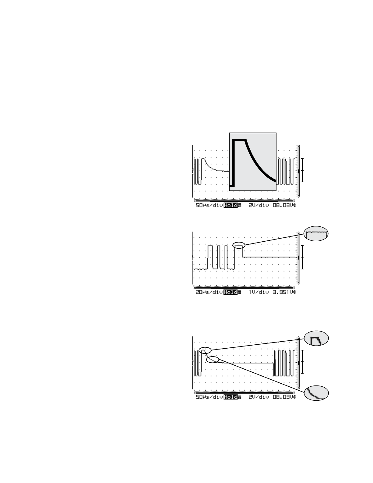
64 THE BLUE BOX LT TROUBLESHOOTING WITH AN OSCILLOSCOPE
USING AN OSCILLOSCOPE TO TEST
A DIGITAL BUS
In troubleshooting a system or a bus, the “Final Activation
Checklist” is always the first and most important step. An Oscilloscope is a visual aid to troubleshoot the bus better.
The Oscilloscope will let one test the stability of the bus
while everything is powered up. This will show if the bus
is getting noise, how clean the bus signal is, if the bus is
properly terminated, if there is a bad device present on
the bus, and give an indication of crimp quality.
Below are some examples where the use of an Oscilloscope is definitely needed:
The Hardware Activation Tests included the “System 1.
Startup and Cabling Guide” passed, but when the system is powered up, devices appear/disappear on the
bus scan.
The Hardware Activation Tests passed, but some de-2.
vices don’t seem to be working if the bus is connected, and the same devices work perfectly fine when
connected directly to a master panel.
Everything else was checked (The Hardware Activa-3.
tion Tests” passed and all devices are good) but the
bus is still unstable.
HOW TO SETUP THE SCOPE FOR TESTING
Make sure the Oscilloscope is not earth grounded in any
way. A battery powered scope is best.
Connect the probe leads to the system’s A & B ter-1.
minals; A “Bus Checker Card” may be used to make
the testing easier. Attach the alligator clip (which is the
ground lead of the probe) to the bus checker card’s
B terminal, then connect the main probe lead (which
is usually a retractable hook tip) to the bus checker
card’s A terminal.
Adjust the vertical & horizontal controls accordingly 2.
and set the input coupling to DC. You should be able
to see your bus signal which is a “Square Wave Signal.”
The advisable setting would be “1.0 volts/div” & “(20 3.
µs to 50 µs) sec/div” this should be able to let one see
a decent size waveform on the screen. (10-1 Probe).
A completely “Stable Bus” should show a clean & bal-4.
anced square wave signal. The baseline is centered at
“0” and never changes.
If the bus is not terminated properly, some “ringing” 5.
may be seen. With less loading, the Vpp is higher. If
there are not bad devices, the baseline is still at Zero.
+V = -V
+V = -V
Ideal wave form; Square waves with no ring or dampen-
ing means the bus is terminated. +V = -V means no bad
devices.
+V = -V
Problematic: Dampened square wave means the bus is
missing one or both terminators. +V = -V means no bad
devices.
LCDBBTSWO03Sept08
Page 65
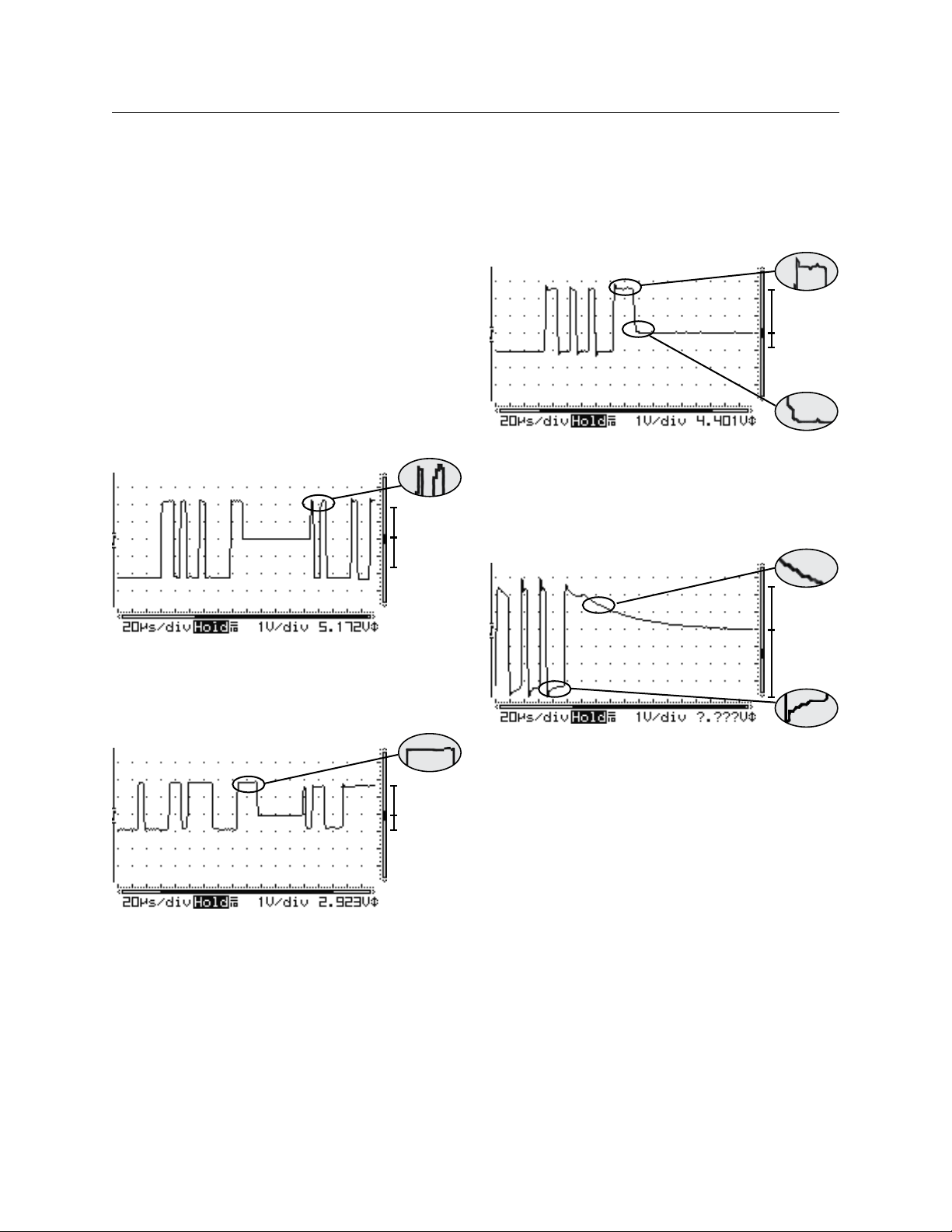
THE BLUE BOX LT TROUBLESHOOTING WITH AN OSCILLOSCOPE 65
USING AN OSCILLOSCOPE TO TEST
A DIGITAL BUS (Continued)
With a par tially bad device, it is sometimes hard to 6.
distinguish because it looks very similar to a good bus.
One has to carefully examine the waveform and see
if the baseline is centered at Zero.
A bad device causes the baseline to shift and become 7.
unbalanced. (Baseline is not at Zero anymore). Below
are three examples where A & B are not equal.
Use the Bus-Splitting technique to find the problem.8.
Problematic: Ringing and dampened square wave means
that the bus is missing one or both terminators. +V ≠ -V
means damaged devices. Usually caused by over-voltage:
static, lightning, or line voltage.
+V = -V
+V ≠ -V
Problematic: Ringing on peak of square wave means the bus
is missing one or both terminators. +V = -V means no bad
devices.
+V ≠ -V
Problematic: Clean square waves mean the bus is terminated. But +V ≠ -V means damaged devices. Usually caused
by over-voltage: static, lightning, or line voltage.
LCDBBTSWO03Sept08
+V ≠ -V
Problematic: Ringing and extremely dampened square wave
means the bus is missing one or both terminators. +V ≠
-V means damaged devices. Usually caused by over-voltage:
static, lightning, or line voltage.
Page 66
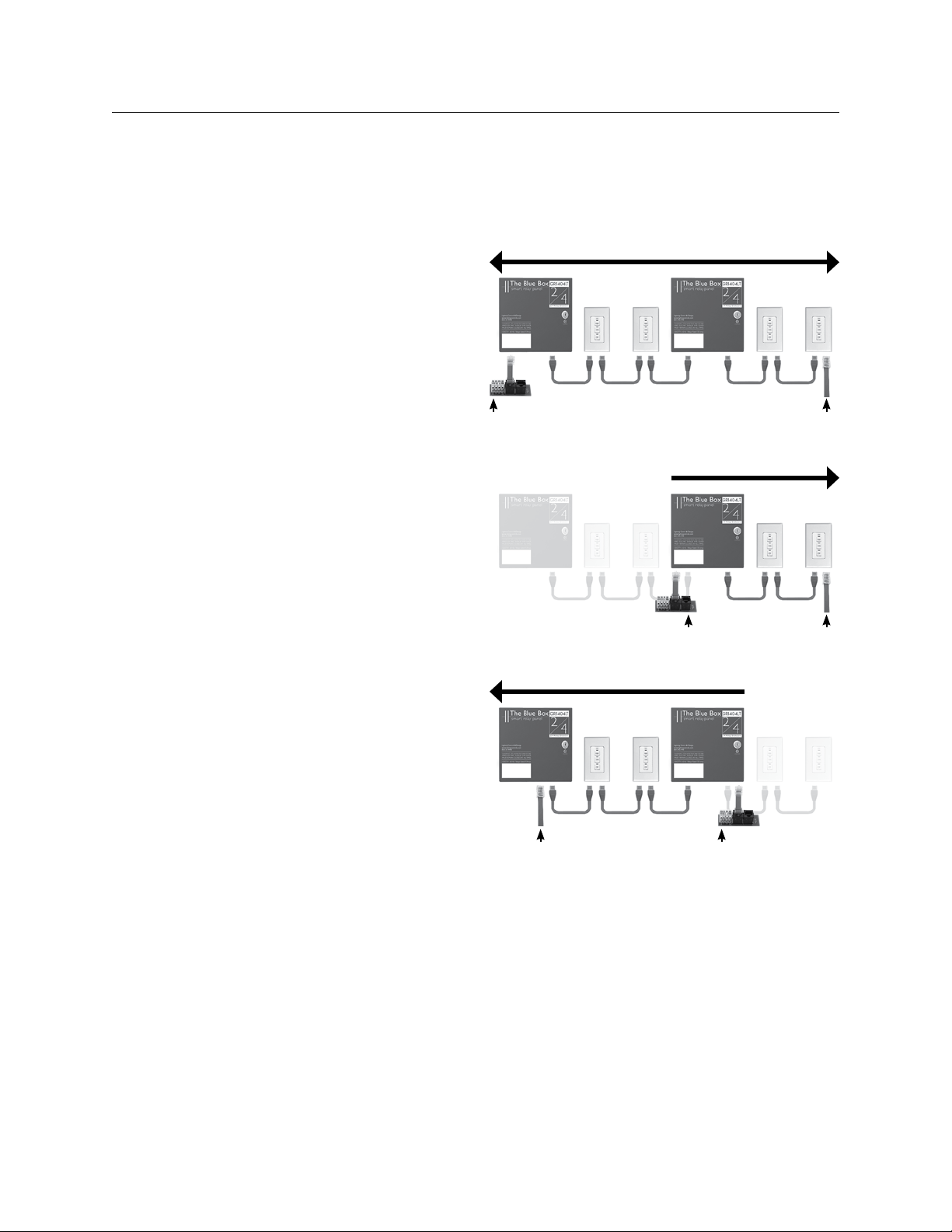
66 THE BLUE BOX LT TROUBLESHOOTING WITH AN OSCILLOSCOPE
BUS SPLITTING TECHNIqUE
Note:To speed up troubleshooting when readings are
!
less than 200Ω on the Continuity or Short-Circuit test,
refer to the “Bus Length Chart” on page 4 before splitting
the bus; this can provide an approximate distance to a
shorted pair or extra terminator from the test point.
On the middle device of the bus, disconnect one Cat. 1.
5 cable to create two smaller “half-buses”.
Test each “half-bus” to find the side with the out-of-2.
range values.
Repeat steps 1 & 2 on the out-of-range “half-bus,” 3.
to create another “half-bus” until the cable, crimp or
device creating the out of range measurements is located.
The idea is to split a bus in half and then half again – over
and over until the bad area has been located. It is also OK
to visually inspect each cable, crimp or device to detect the
problem.
Bus Checker Card
Data/Power Jumper
Bus Checker Card
Data/Power Jumper
Data/Power Jumper
Bus Checker Card
LCDBBTSWO03Sept08
Page 67

®
™
THE BLUE BOX
LT
PROGRAMMING
LCDBBP03Sept08
®
Lighting Control & Design
905 Allen Ave, Glendale CA 91201
Tel: 800-345-4448 • www.lightingcontrols.com
Page 68

68 THE BLUE BOX LT PROGRAMMING
TABLE OF CONTENTS
Programming ..............................................................................69
DTC Clock Navigation Basics ..............................................................69
Manual Control of Relays..................................................................70
Programming Switches or DI Inputs .........................................................71
Time Schedules ..........................................................................73
Programming a Blue Box LT Photocell .......................................................76
To Add a Holiday List to a Schedule.........................................................77
More Data on Scheduled Events............................................................78
Group Types.............................................................................80
Programming Groups .....................................................................81
Additional Groups Parameters .............................................................82
Group FAQs ............................................................................83
Other System / Set Up Programming .......................................................86
Daylight Saving Time ......................................................................86
Keyboard Lock Code .....................................................................87
Time Schedule Programming Examples ......................................................88
Exercise #1- Contact Closure Device Controlling 4 Relays .....................................88
Exercise #2 - Contact Closure Device Controlling 10 Relays....................................88
Exercise #3 - Time Schedules with Override Switches .........................................88
Exercise #4 - Retail Store .................................................................89
LCDBBP03Sept08
Page 69
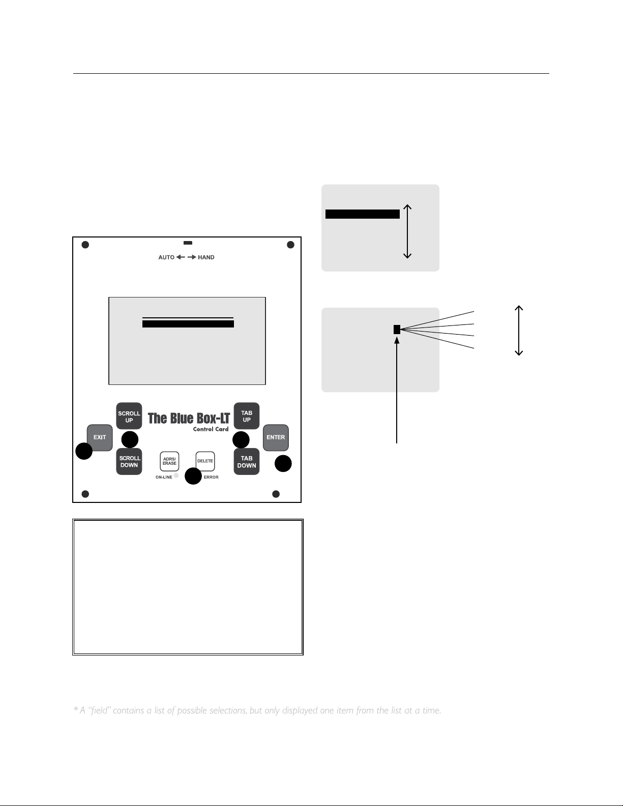
THE BLUE BOX LT PROGRAMMING 69
DTC CLOCk NAvIGATION BASICS
Most devices can be programmed from the DTC
(Digital Time Clock) in the master Lighting Control
Panel (LCP).
USER MENU
MANUAL OVERRIDE
REVIEW SCHEDULE
GROUP LOADS
PROGRAM SWITCH
SETUP MENU
1
3
4
5
2
CALL OUT LEGEND:
SCROLL through choices in one fi eld*1.
TAB to position the cursor2.
DELETE information or programming about 3.
an item. Use caution.
ENTER to select4.
EXIT to leave a screen.5.
TAB moves the cursor through a screen
SWITCHES PAGE 1-1
#04: SWITCH 4
#05: SWITCH 5
#06: SWITCH 6
#07: SWITCH 7
#08: SWITCH 8
#09: SWITCH 9
#10: SWITCH 10
SCROLL to choose one item from a fi eld.*
SWI ID05-5 TOGGLE
EDIT: LCP-2 LOAD-1
Load 4
Load 3
Load 2
Load 1
This“ eld” contains a list of possible
selections, but only displays one item
from that list at a time.
TAB moves the cursor through a screen
SWITCHES PAGE 1-1
#04: SWITCH 4
#05: SWITCH 5
#06: SWITCH 6
#07: SWITCH 7
#08: SWITCH 8
#09: SWITCH 9
#10: SWITCH 10
SCROLL to choose one item from a fi eld.*
SWI ID05-5 TOGGLE
EDIT: LCP-2 LOAD-1
Load 4
Load 3
Load 2
Load 1
This“ eld” contains a list of possible
selections, but only displays one item
from that list at a time.
* A “field” contains a list of possible selections, but only displayed one item from the list at a time.
PROGRAMMING
DTC CLOCk NAvIGATION BASICS
Most devices can be programmed from the DTC
(Digital Time Clock) in the master LCP (Lighting
Control Panel).
LCDBBP03Sept08
Page 70
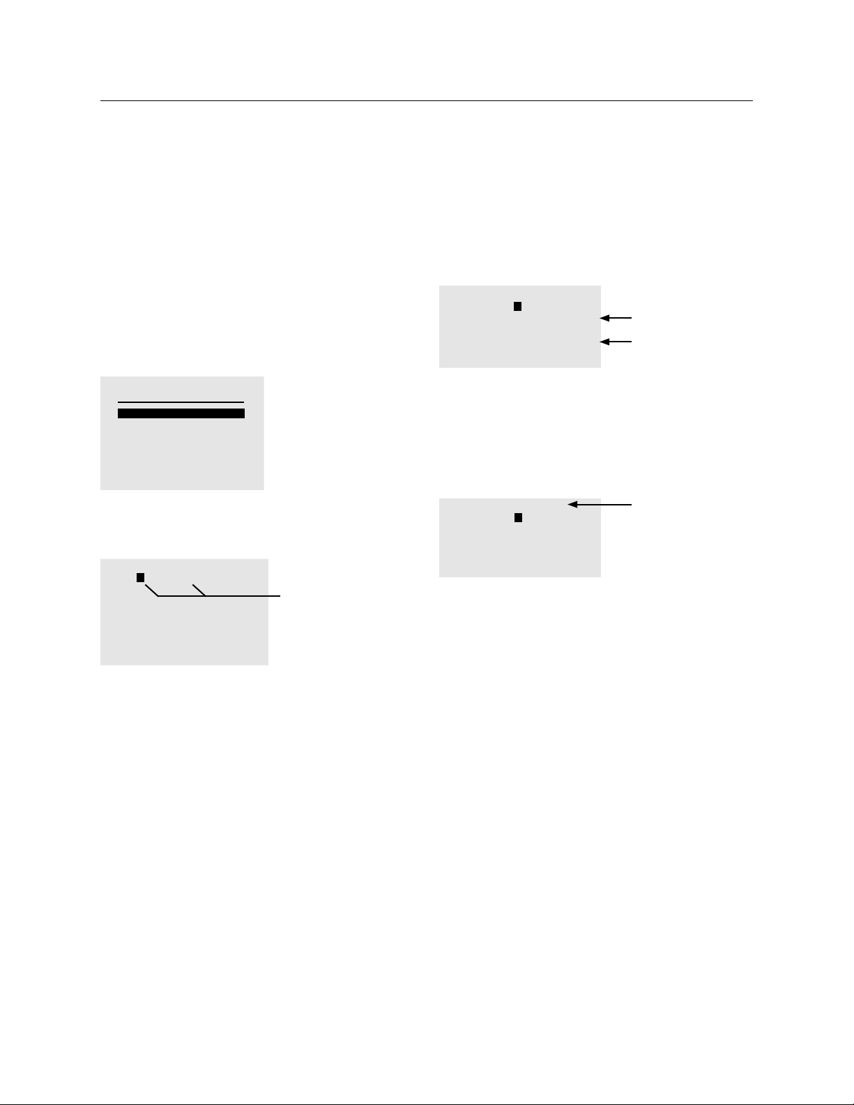
70 THE BLUE BOX LT PROGRAMMING
MANUAL CONTROL OF RELAYS
Manually control and visually check the (on/off) status
of any relays(s) in any panel(s).
To Start
TAB once or twice to get started. The USER 1.
MENU will display.
TAB to MANUAL OVERRIDE.2.
USER MENU
MANUAL OVERRIDE
REVIEW SCHEDULE
GROUP LOADS
PROGRAM SWITCH
SETUP MENU
ENTER to select the MANUAL CONTROL screen.3.
To Navigate to a LOAD (Relay)
MANUAL CONTROL AU
LCP-1 LOAD-1
1- 3■ 5■ 7■ 9- 11- 13- 15-
2- 4- 6- 8■ 10- 12- 14- 16-
SCROLL to select LCP
TAB to LOAD
SCROLL to select LOAD
ENTER to toggle status
To Control a LOAD (Relay):
ENTER to toggle the status of the LOAD “off” 8.
or “on”.
MANUAL CONTROL AU
LCP-1 LOAD-1
1■ 3■ 5■ 7■ 9■ 11- 13- 15■
2- 4- 6- 8■ 10- 12- 14- 16-
LOAD 15 is on. .
LOAD 16 is off.
- indicates the LOAD is off
■ indicates the LOAD is on
There are other relays statuses. Refer to “Groups
FAQ” for a more complete description of all of the
different relay statuses.
MANUAL CONTROL AU
LCP-1 LOAD-1
1■ 3■ 5■ 7■ 9- 11- 13- 15-
2- 4- 6- 8■ 10- 12- 14- 16-
AU indicates LCP 1 is
in AUTOMATIC mode.
“MN” indicates LCP 1
is in HAND mode
Press EXIT several times to get back to the main 9.
screen.
TAB to LCP-1(Lighting Control Panel 1).4.
SCROLL to select the correct LCP (for systems 5.
with multiple LCPs).
TAB to LOAD-1.6.
SCROLL up or down to select the LOAD (relay) 7.
to control.
LCDBBP03Sept08
Page 71

THE BLUE BOX LT PROGRAMMING 71
PROGRAMMING SWITCHES OR DI INPUTS
To Navigate to Digital Switch or DI Card
TAB to start.1.
TAB to PROGRAM SWITCH and ENTER to 2.
select.
USER MENU
MANUAL OVERRIDE
REVIEW SCHEDULE
GROUP LOADS
PROGRAM SWITCH
SETUP MENU
If needed SCROLL to the correct Page.3.
SWITCHES PAGE 1-2
#04: switch 4
#05: switch 5
#06: switch 6
#07: switch 7
#08: switch 8
#09: switch 9
#10: switch 10
Indicates Page 1 of 2
If cursor starts here,
multiple pages exist
with switches on each.
SCROLL to navigate
to the correct page.
TAB to the correct Switch.4.
ENTER to select (Switch 11).5.
SWITCHES PAGE 2-2
#11: Switch 11
#12: switch 12
#16: switch 13
This is the name of
the switch.
This is the address of
the switch.
To Select Control Type
Before adding or deleting loads it is important to
determine the Control Type (see the Control Types
section of this manual).
Tip: Most common Control Types for switches are
TOGGLE, ON, and OFF.
SCROLL to select Control Type.1.
SWI ID11-6 TOGGLE
EDIT: LCP-1 LOAD-1
Indicates Control Type
Note: Switches may control any number of loads. If
more than 8 loads are selected, the system will create
a Group upon exiting. When prompted to create a
new Group, select “YES” (See Groups Section for
more information).
To Add or Delete Loads for all Control Types
(except Mixed Mode)
TAB to LCP 1.1.
SCROLL to select LCP (1,2,3 etc.).2.
TAB to LOAD 1.3.
SWI ID11-6 TOGGLE
EDIT: LCP-1 LOAD-1
LCP1: 1
“Toggle” Control Type
has been selected
LCP1 Relay1 has been
added to the Load
Summary
TAB to the correct Button/Input.6.
ENTER to select.7.
SELECT BTN SWI ID#11
SETUP PAGE 1-1
B1: BUTTON 1
B2: BUTTON 2
B3: BUTTON 3
B4: BUTTON 4
B5: BUTTON 5
B6: BUTTON 6
LCDBBP03Sept08
Switch ID#11
SETUP is for advanced
programming only!
Button6, Switch ID11
SCROLL to the LOAD you want to add or 4.
delete.
ENTER once to select LOAD - it will be added to the 5.
Load Summary.
ENTER again to delete LOAD from the Load 6.
Summary.
Repeat to add or delete more LOADs.7.
EXIT up to main menu.8.
To Add or Delete Loads for Mixed Mode:
Page 72
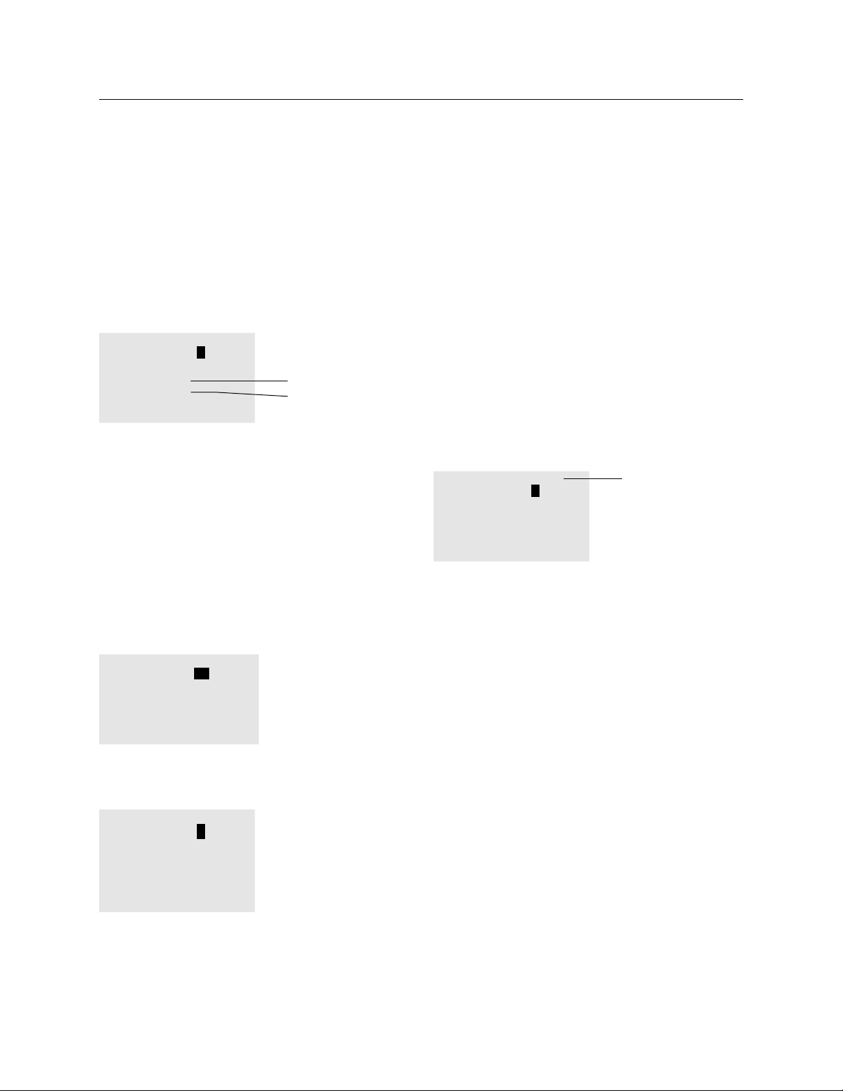
72 THE BLUE BOX LT PROGRAMMING
SCROLL to select LCP (1,2,3, etc.).1.
TAB to LOAD 1.2.
SCROLL to the LOAD you want to add or 3.
delete.
ENTER once to add to ON Load Summary.4.
SWI ID13-1 MIXED MODE
EDIT: LCP-2 LOAD-3
ON LCP1: 1-3
OFF LCP2: 1-3
ENTER twice to add to OFF Load Summary.5.
ENTER third time to delete LOAD from Load 6.
Summary.
Repeat to add or delete more LOADs.7.
EXIT up to main menu.8.
To Delete a Load:
TAB and SCROLL to select LOAD.1.
ENTER until the LOAD is deleted from the Load 2.
Summary.
SWI ID13-1 TOGGLE
EDIT: LCP-2 LOAD-4
LCP1: 2-5,12
LCP2: 1,4
Mixed Mode
Load Summary
shows LOADS to be
switched ON and
switched OFF
Delete LCP2:4 from
Load Summary
1.TAB to LCP 1
2. SCROLL to LCP 2
3. TAB to LOAD 1
4. SCROLL to LOAD 4
5. ENTER to remove
from Load Summary
Programming an Occupant Sensor
Once the occupant sensor has been connected to
the low-voltage dry contact inputs in the DI card, the
inputs must be programmed.
Occupant sensor contacts send a “Maintain”
type closure to the inputs on the DI card and are
therefore programmed as a “Maintain” Control Type
(or Maintain Group for more than 8 relays).
To program a DI Input:
Navigate to the DI card inputs: USER MENU > PRO-1.
GRAM SWITCH > SWITCH # > BUTTON #.
SCROLL to select MAINTAIN as the Control Type.2.
SWI ID13-1 MAINTAIN
EDIT: LCP-2 LOAD-5
Occupant Sensors
use a MAINTAIN
Control Type
LCP2: 4,5
Add/delete LOADs (refer to Add or Delete Loads 3.
section).
If more than 8 relays are added, accept the
creation of a new Group upon EXITing.
To use an existing Group SCROLL to the Control
Type and select the Group.
For more information on Control Types, Groups and
Group types, refer to the relevant sections in the
O&M.
SWI ID13-1 MIXED MODE
EDIT: LCP-2 LOAD-3
ON LCP1: 1-3
OFF LCP2: 1-3
Delete “LCP1:3” from
“ON” Load Summary
1. TAB to LOAD 1
2. SCROLL to LOAD 3
5. ENTER until
removed from (ON &
OFF) Load Summary
LCDBBP03Sept08
Page 73
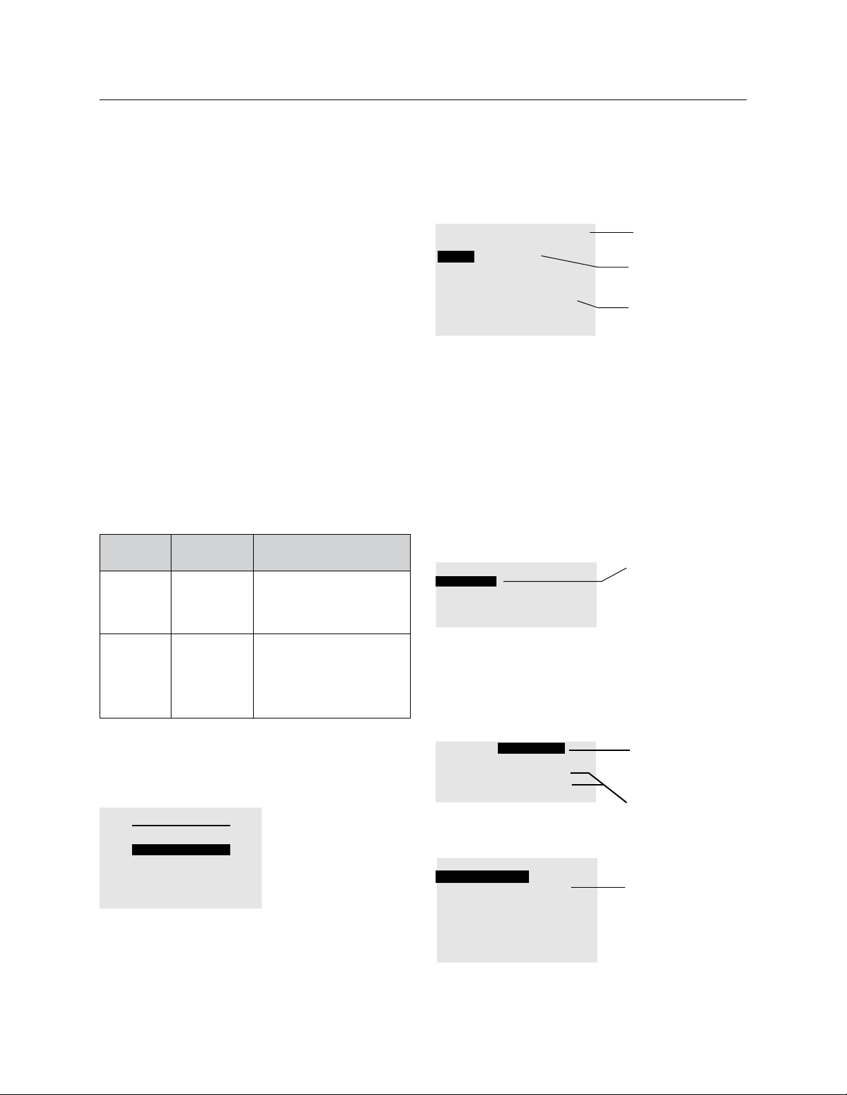
THE BLUE BOX LT PROGRAMMING 73
TIME SCHEDULES
Introduction to Time Schedules
There are a few important things to note before
programming a Time Schedule:
Time Schedules DO NOT control relays – they
control Groups and have Scheduled Events (when
things are on and off). Groups contain Loads (relays)
and describe “behaviors” pertaining to the schedule.
For more information about groups refer to Groups
Section.
When creating or modifying a schedule.
Scheduled the Events.1.
Add a group which contains loads (relays) and 2.
their behaviors.
Example:
Name
Schedule 1 Group 1
Group 1
What it
Controls
LCP1:
relays 1-5
LCP2:
relays 3 & 9
Its Behaviors
On 9am
Off 5pm
Mon-Fri
When the group is “off ”,
relays may only be turned
on for 2 hours (relay-timer)
Prior to shutting lights off,
relays issue a blink warning.
To Navigate to Any Schedule (up to 32).
TAB to start.1.
TAB to REVIEW SCHEDULE and ENTER to 2.
select.
USER MENU
MANUAL OVERRIDE
REVIEW SCHEDULE
GROUP LOADS
PROGRAM SWITCH
LCDBBP03Sept08
SETUP MENU
A list of the first 6 (of 32) schedules will be 3.
displayed. If needed SCROLL to the correct Page
SCHEDULES PAGE 1-6
Name: SCHEDULE 1
SCH 1 UNUSED
SCH 2 UNUSED
SCH 3 UNUSED
SCH 4 ===> NO LOADS
SCH 5 UNUSED
SCH 6 UNUSED
Page 1 of 6. SCROLL
to view more pages
“UNUSED” means
sch unprogrammed
“NO LOADS” means
sch is programmed no loads assigned..
TAB to a new or existing SCHEDULE and 4.
ENTER to select.
TAB to EVERY DAY (default) and SCROLL to 5.
select one of three schedule types:
Every Day.1.
Mon-Fri, Sat Sun.2.
By Day.3.
For more information on the three schedule types
refer to Scheduled Types Section.
SCH 1 EXCEPT NONE
EVERY DAY
ON TIME: 09:00 AM
OFF TIME: 05:00 PM
SCROLL to adjust
EVERY DAY•
M-F, S, S•
BY DAY•
For Every Day or Mon-Fri-Sat-Sun Schedules:
TAB to each ON TIME and OFF TIME.1.
SCROLL to adjust the Scheduled Event (refer to 2 .
“Scheduled Events” Section for more information).
SCH 1 EXCEPT NONE
EVERY DAY
ON DUSK -30mins
OFF DAWN +30mins
To Add or to edit
Holiday Lists refer to
Holiday Section
SCROLL to adjust
Scheduled Event
Every Day Schedule - same on & off times 7 days/wk.
SCH 1 EXCEPT NONE
MONDAY - FRIDAY
ON TIME: 09:00 AM
OFF TIME: 05:00 AM
SAT ON TIME: 11:00 AM
OFF TIME: 03:00 PM
SUN none
none
Tab to each Scheduled
Event and SCROLL to
adjust.
Page 74
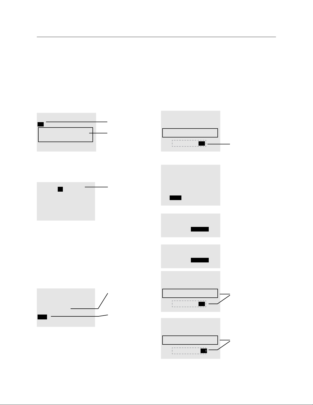
74 THE BLUE BOX LT PROGRAMMING
For “By Day” Schedule
With different Scheduled Events for each day of
the week, the “BY DAY” schedule offers the most
comprehensive feature set of all schedule types.
SCH 1
BY DAY H1 H2
Mo Tu We Th Fr Sa Su
ON TIME: 09:00:00a
OFF TIME: 05:00:00p
from Jan 1 to Dec 31
Monday is highlighted
This is the summary
of Monday’s
Scheduled Events
Tab to any day and ENTER to edit that day.1.
TAB to ON TIME or OFF TIME and SCROLL to 2.
adjust Scheduled Events.
ON TIME: 11:30:00 am
OFF TIME: 02:00:00 pm
ADJUST THESE DAYS:
Mon
every day
This is the summary
of Monday’s
Scheduled Events in
editing mode
To Add Scheduled Events from one day to multiple
days (“By Day” schedules only)
TAB to Every Day (bottom of screen).3.
SCROLL and 4.
ENTER to select the desired day
or group of days. Repeat until all desired days
are selected. The list of selected days will be
displayed (see below).
EXIT. Selected days will be updated.5.
ON TIME: 11:30:00 am
OFF TIME: 02:00:00 pm
ADJUST THESE DAYS:
Mon, Tue, Wed
Thu
This is a list of more
days the Scheduled
Events for Monday
will be copied to
TAB to here. SCROLL
and ENTER to add
days to the above list.
Repeat steps 1-5 to edit schedules for other days.6 .
To Select a Start-Date and End-Date
1. TAB to JAN and SCROLL to adjust.
2. TAB to 1 and Scroll to adjust.
3. Repeat as above to edit the end-date.
4. EXIT when complete.
SCH 1
BY DAY H1 H2
Mo Tu We Th Fr Sa Su
ON TIME: 09:00:00a
OFF TIME: 05:00:00p
from Sep 1 to Jun 15
Edit Schedule start
date and end date
here.
Sample Schedules:
SCH 1 EXCEPT NONE
MONDAY - FRIDAY
ON dusk -30 mins
OFF TIME: 01:00 am
SAT dusk -30 mins
OFF TIME: 10:00 pm
SUN NONE
NONE
SCH 1 EXCEPT NONE
EVERY DAY
ON PCEL: 06:00am
OFF PCEL: 09:00am
SCH 2 EXCEPT NONE
EVERY DAY
ON PCEL: 03:00pm
OFF PCEL: 07:00pm
SCH 8
BY DAY H1 H2
Mo Tu We Th Fr Sa Su
ON TIME: 07:00:00a
OFF TIME: 07:00:00p
from Sep 1 to Jun 15
SCH 9
BY DAY H1 H2
Mo Tu We Th Fr Sa Su
ON TIME: 11:00:00a
OFF TIME: 02:00:00p
from jun 16 to aug 31
These lights will be
switched on 30 mins
prior to dusk Mon-Sat.
Off time on Saturday
is earlier (10pm).
Lights are off Sunday.
These two schedules
when combined will
control outdoor egress
and parking lighting
before and after
hours for employees
but only when it is
dark out (during the
short daylight hours of
winter.
These two schedules
control lighting at a
school in tandem.
During the school year
(Sept 1 to Jun 15)
lights operate on one
schedule (SCH 8)
During summer break
(Jun 16 to Aug 31),
lights operate on a
much shorter schedule
(SCH 9)
LCDBBP03Sept08
Page 75
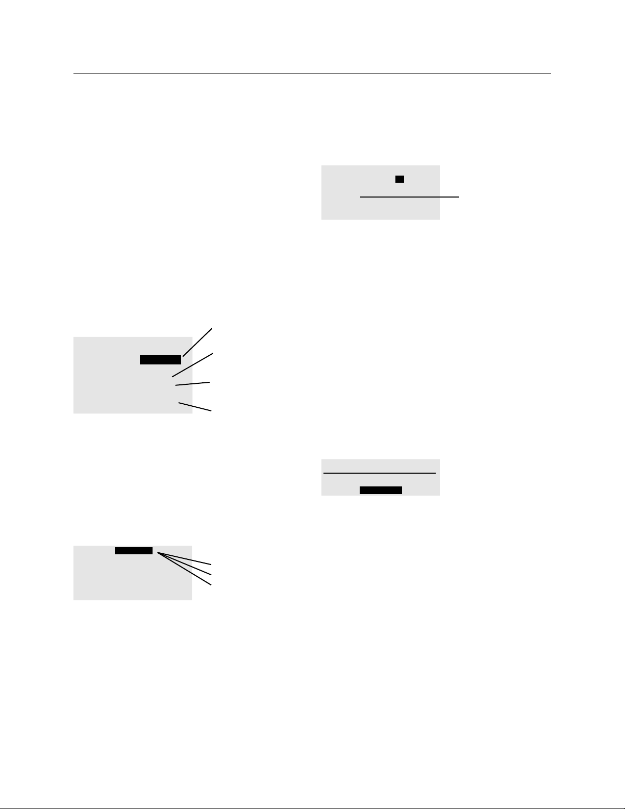
THE BLUE BOX LT PROGRAMMING 75
To Add Loads to a Schedule
When you have completed programming a time
schedule, the next step is to add the loads to be
controlled.
To save the schedule press EXIT. TAB to “yes” 1.
and ENTER to save the schedule. The clock will
take a second to save the changes and exit back
to the SCHEDULE LIST menu.
TAB to “NO LOADS” and ENTER to add loads 2.
to the schedule.
Schedule 1 is
programmed and has
no loads
SCHEDULES PAGE 1-6
Name: SCHEDULE 1
SCH 1 ==> NO LOADS
SCH 2 UNUSED
SCH 3 UNUSED
SCH 4 ==> GROUP 4
SCH 5 UNUSED
SCH 6 ==> DISABLED
Schedule 3 is not
programmed
Schedule 4 is
programmed and
controls GROUP 4
Schedule 6 is
programmed, but is
disabled
TAB to MAINTAIN and SCROLL to choose the 3.
Group Type.
Quick Tip: Choose MAINTAIN for outdoor lighting
and MNTN + BLINK for indoor lighting. For a more
complete understanding of Group Types, refer to the
Group Section later in this manual.
GROUP1 MAINTAIN
EDIT: LCP-2 LOAD-5
LCP1:1-5
LCP2:3,4
Choices are
MAINTAIN•
MNTN + TIMER•
MNTN + BLINK•
TAB to LOAD 1.4.
SCROLL to the desired Load (relay) and ENTER 5.
to add to the Load Summary.
LCDBBP03Sept08
Repeat the TAB and SCROLL sequence and add 6.
as many loads as required.
GROUP1 MAINTAIN
EDIT: LCP-2 LOAD- 5
LCP1: 1-5 and LCP
LCP1:1-5
LCP2:3,4
3,4 are in the Load
Summary
Additional steps for MAINTAIN + TIMER and
MAINTAIN + BLINK Groups
These steps are considered best practice for indoor
lighting, and include after-hours relay timers.
MAINTAIN groups can EXIT at this point.
With “MNTN + __” highlighted, ENTER to set 7.
advanced options.
TAB to AUTOMATIC ON. SCROLL to change 8.
to NO AUTOMATIC ON if desired. NO
AUTOMATIC ON means lighting will not
automatically be switched on in the morning by
the clock but must be manually switched on by
an occupant. This is considered an energy savings
feature. AUTOMATIC ON will turn the lights
on by the clock, whether occupants are present
or not.
GROUP1 PARAMETERS
AUTOMATIC ON
SET TIMER
TAB to SET TIMER and ENTER to program 9.
the after-hours relay timers. This features allows
occupants to switch lights on after the scheduled
time, but only for a timed duration. This is an
energy savings feature and is required by most
energy codes.
TAB to the Hours/Minutes/Seconds display 10.
and TAB/SCROLL to set the Hours/Minutes
and Seconds of the after-hours timer. 2:00:00 is
usually recommended.
Page 76
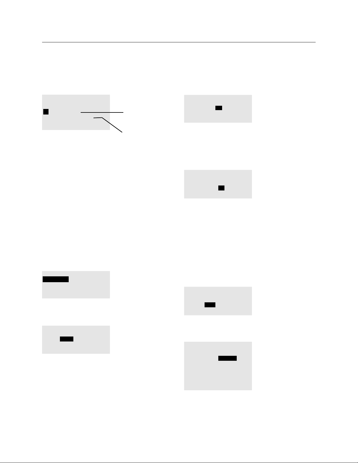
76 THE BLUE BOX LT PROGRAMMING
TIMER SETTING
REGULAR TIMER MODE
30:59:59 H/M/S
BLINK ONE: 05:00 M/S
BLINK TWO DISABLED
After Hours Timer is
for all relays in this
Group - relays will be
in a Timer-Mode to
conserve energy
BLINK is only for
MNTN+BLINK group
TAB to 05:00 and TAB and SCROLL to change 11.
the Blink Timer. EXIT twice when complete to
return to the Groups screen (Load Summary).
EXIT when complete.12.
PROGRAMMING A BLUE BOX LT PHOTOCELL
When an outdoor photocell is plugged directly
into The Blue Box LT master panel, the photocell is
programmed as part of a time schedule (available for
schedules 1-8 only).
Navigate to: USER MENU>REVIEW SCHEDULE.1.
Use the SCROLL and TAB keys to navigate to 2.
the desired schedule. ENTER to select.
SCROLL to select schedule type (EVERYDAY, 3.
BY DAY, M-F S S).
SCH 1 EXCEPT NONE
EVERY DAY
ON TIME:09:00am
OFF TIME:05:00pm
SCROLL to select
schedule type
TAB to ON TIME or OFF TIME for each day or 4.
group of days and SCROLL to select PCEL.
SCH 1 EXCEPT NONE
EVERY DAY
ON PCEL:09:00am
OFF PCEL:05:00pm
SCROLL to select
PCEL
TAB to the time settings after ON PCEL and 5.
SCROLL to select an “on” time. This is the time
that the photocell will be “enabled.” When
enabled, the group is switched on only if the light
levels are below the ON trigger, otherwise they
will remain OFF until the light levels drop below
the ON trigger.
SCH 1 EXCEPT NONE
EVERY DAY
ON PCEL: 03:00pm
OFF PCEL: 05:00pm
TAB to hours
and minutes and
SCROLL to select
“on” time
TAB to the time settings after OFF PCEL and 6.
SCROLL to select an “off ” time. This is the time
that the photocell will be “disabled” (not allowed
to operate). When the photocell is disabled, the
group is also switched off.
SCH 1 EXCEPT NONE
EVERY DAY
ON PCEL: 03:00pm
OFF PCEL: 10:00pm
TAB to hours
and minutes and
SCROLL to select
“off ” time
For outdoor lighting, we recommend an “on” time of
about 3:00 PM and an “off” time that coincides with
the scheduled “off ” time.
For daylight harvesting use the PCC3 which offers
settings more appropriate for daylight harvesting.
(See GR2400 system catalog).
Adjusting Photocell Triggers
With the cursor on PCEL, ENTER to edit the 7.
trigger settings.
SCH 1 EXCEPT NONE
EVERY DAY
ON PCEL: 03:00pm
OFF PCEL: 10:00pm
TAB to either PCEL
and ENTER to go to
trigger settings
SCROLL to adjust the “off ” Time Delay (10 8.
minutes is usually recommended).
On Board Photocell
Reading: 0
Delay to off: 10 mins
Off when when light level
rises above: 30
Delay to On:5mins
On when light level
falls below: 20
In trigger settings you
can edit the “on” delay
and the “off ” delay
and the on and off
triggers
The default setting for the “off” trigger (rises 9.
above) is 30. The default setting for the “on”
LCDBBP03Sept08
Page 77
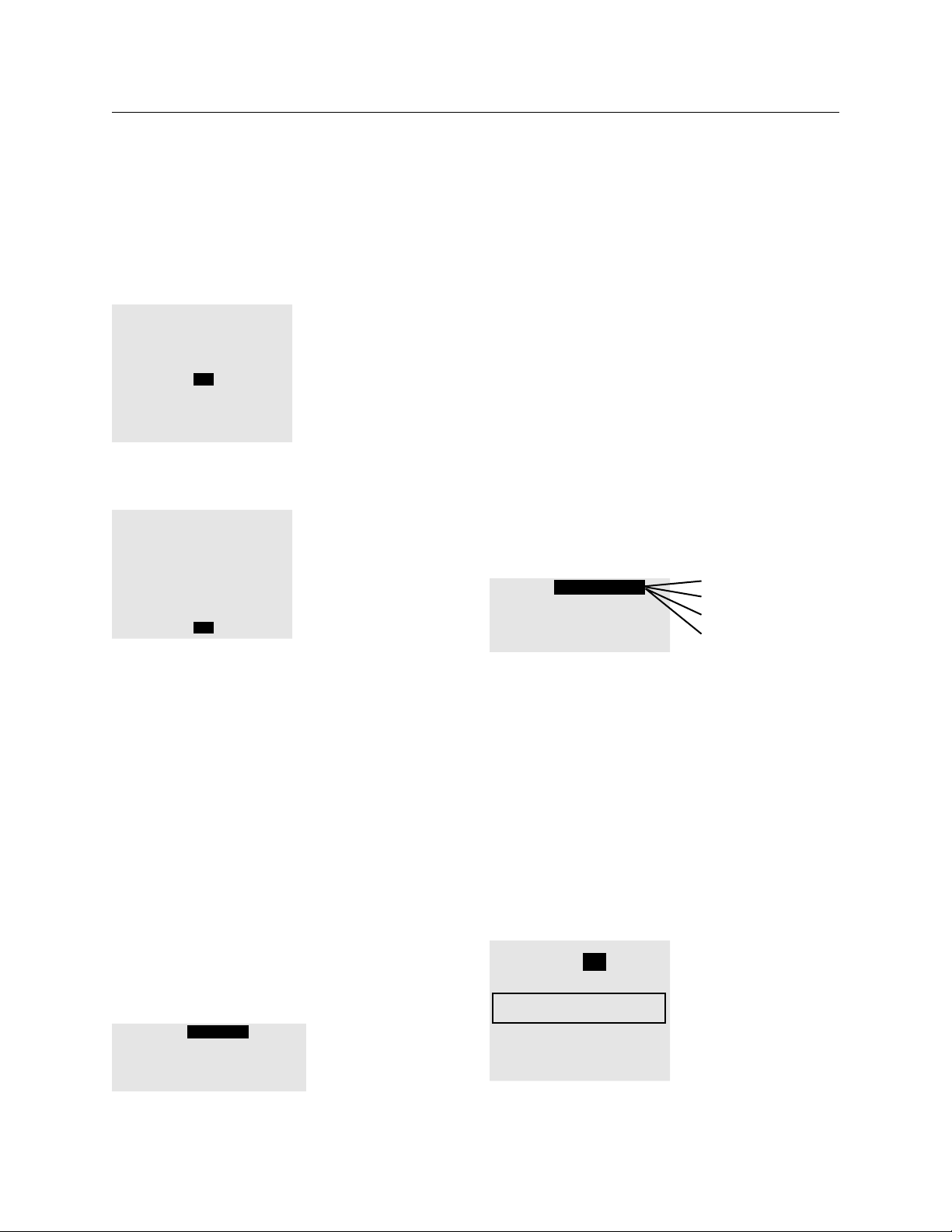
THE BLUE BOX LT PROGRAMMING 77
trigger (falls below) is 20. TAB DOWN to each
trigger and and SCROLL to adjust.
On Board Photocell
Reading: 0
Delay to off: 10Mins
Off when when light level
rises above: 40
Delay to On:5Mins
On when light level
falls below: 41
TAB DOWN to “off”
trigger (raises above)
and SCROLL to adjust.
ON and OFF triggers
should remain at least
10 points apart.
TAB to ”on” trigger (falls below) and SCROLL 10.
to adjust.
On Board Photocell
Reading: 0
Delay to off: 10Mins
Off when when light level
rises above: 40
Delay to On:5Mins
On when light level
falls below: 41
Tip: A good way to determine the best trigger
settings is to do the above steps at a time when
daylight about matches when you want the lights
to go on or off. For example, set the Off (raises
above) trigger in the morning when the sun is
just coming up. Check the light level reading on
the clock when the area is bright enough for the
lights to shut off and use this reading as the “Off ”
value. Similarly, set the On (falls below) trigger in
the evening when it is just getting dark enough
so that the lights should come on. Check the
light level reading at that time and use it as your
“On” value.
EXIT and SAVE.11.
To add loads(relays) to this schedule, refer to 12.
“Adding Loads to a Schedule”. The PCELL
schedule is always programmed as MAINTAIN.
LCDBBP03Sept08
GROUP 1 MAINTAIN
EDIT: LCP-1 LOAD-5
LCP1:1,2,5
Use a MAINTAIN
group for
photosensor
settings.
TO ADD A HOLIDAY LIST TO A SCHEDULE
The system offers up to 2 separate editable Holiday
Lists. This portion of the menu allows you to select
from pre-existing holiday lists. See Edit/Create
Holiday List for instructions on how create or edit a
new Holiday List.
Every Day & Mon-Fri, Sat, Sun Schedule
These two schedules only allow the Holiday Lists to
be exempt from the schedule.
Follow this path: USER MENU › REVIEW 1.
SCHEDULE.
SCROLL to the correct page and then TAB to the 2.
SCHEDULE you wish to add a Holiday List to.
In the Schedule, TAB to EXCEPT NONE.3.
SCH 1 EXCEPT NONE
EVERY DAY
ON TIME: 09:00 AM
OFF TIME: 05:00 PM
Except None
Except H1
Except H2
Except H1 + H2
SCROLL to select the desired Holiday Exception.4.
Continue programming this schedule or Exit and 5.
Save.
Holiday List in “By Day” Schedule
This schedule allows one or both of the Holiday Lists
to be exempt, or even a new schedule created just
for the days included in the Holiday List.
Follow this path: USER MENU › REVIEW 1.
SCHEDULE.
SCROLL to the correct page and then TAB to 2.
the SCHEDULE you wish to add a Holiday List.
SCH 1
BY DAY H1 H2
Mo Tu We Th Fr Sa Su
ON TIME: 09:00:00a
OFF TIME: 05:00:00p
from Jan 1 to Dec 31
ENTER each
Holiday List to
edit the Holiday
Options
Page 78
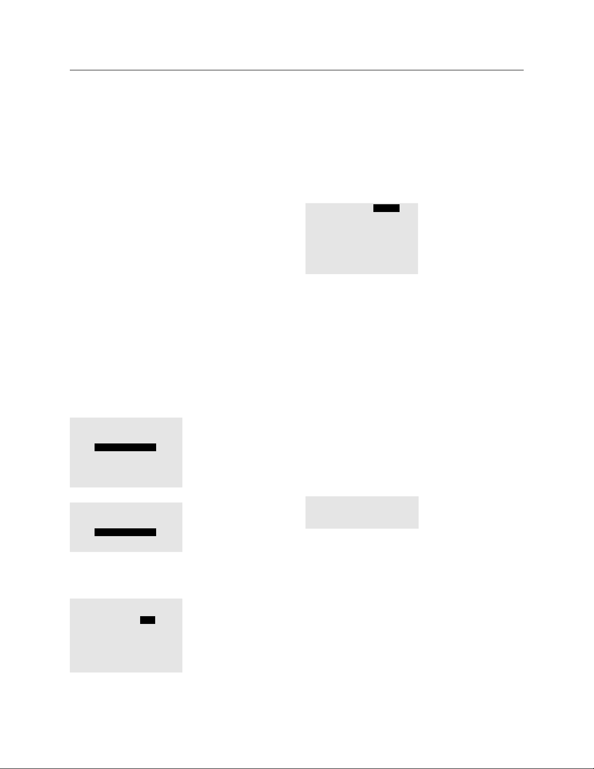
78 THE BLUE BOX LT PROGRAMMING
TAB to either H1 or H2. – the two Holiday Lists. 3.
Both can be selected, but only individually.
ENTER to go to the Holiday options menu.4.
SCROLL to select the desired Holiday option. 5.
There are three choices:
Do Not Omit (default) – the days on this •
holiday list will be included in this schedule.
Omit - the days on this holiday list will not be •
included in this schedule.
ON-OFF schedule - the days on this holiday •
list will have unique schedules.
Program a unique schedule for this Holiday list.6.
Continue programming this schedule or Exit & Save.7.
To Edit a Holiday List
The Holiday lists contain no Holidays until edited. Two
separate holiday lists may be created and edited.
Follow this path: USER MENU › SETUP MENU › 1.
SYSTEM SETUP MENU › EDIT HOLIDAYS.
system setup menu
set time and date
edit HOLIDAYs
system options
what and when?
addressing-bus scan
SCROLL to YES to select.4.
To add new Holidays to a Holiday List, SCROLL 5.
to page 3 and TAB to the first unused date.
HOLIDAY LIST 1 - PAGE 3
Jan 1 2008: no
Jan 1 2008: NO
Jan 1 2008: NO
Jan 1 2008: NO
Jan 1 2008: NO
Jan 1 2008: NO
TAB to month, day and year and SCROLL to 6.
adjust.
EXIT when complete.7.
MORE DATA ON SCHEDULED EvENTS
There are four types of scheduled events, which when
combined, offer an almost limitless set of options and
capabilities.
“On Time” & “Off Time” Scheduled Events
ON TIME or OFF TIME are also called Time of Day
(TOD) events.
To edit an ON or OFF TIME:
TAB to the Hours Minutes, (Seconds for BY 1.
DAY schedules only) and am/pm settings after
ON TIME or and SCROLL to adjust.
select holiday list
to edit
HOLIDAY list 1
Holiday list 2
SCROLL to select page.2.
TAB to the Holiday.3.
Holiday list-page 1
Date: Jan1
New Years :yes
ML King :no
Presidents : no
Easter : no
Memorial : no
Independece : no
ON TIME: 09:00 AM
OFF TIME: 05:00 PM
Astonomical Scheduled Events
The DTC clock offers true astonomical programming.
When setting up the clock, the location is entered
(by city or Lat/Long) and from that all dusk and dawn
times are calculated.
The system even compensates for daylight savings
(where applicable).
“DAWN (or DUSK) + or -” means minutes before
or after dawn or dusk.
LCDBBP03Sept08
Page 79
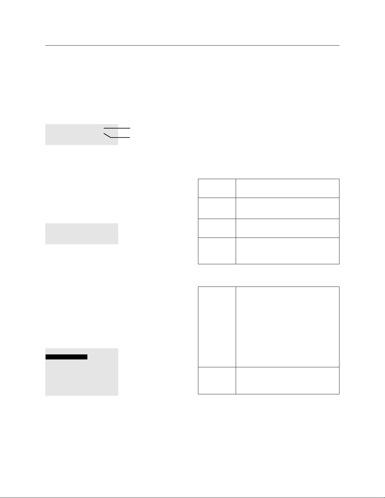
THE BLUE BOX LT PROGRAMMING 79
TAB to “+ 0 mins”.1.
SCROLL up or down to select.2.
ON DUSK -30mins
OFF DAWN +30mins
30 mins. before dusk
30 mins. after dawn
No (NONE) Scheduled Event
In some cases you may desire that nothing at all
happen (e.g. no “off time”). In our schedule, this
Scheduled Event is referred to as “NONE”.
NONE is usually used to disable a specific day or set
of days (i.e. Sunday).
SCROLL to select NONE.1.
ON NONE
OFF NONE
Photocell Scheduled Events
A photocell connected directly to the photocell
input of the Master Blue Box LT, controls relays
only through any of the first 8 time schedules. Each
Schedule may have a unique trigger level, and may
be applied to any relay(s) in any panel(s), creating a
global photocell.
Refer to “Programming a Blue Box LT Photocell” for
programming details.
Mixing Scheduled Events - Custom Schedules
SCH 1 EXCEPT NONE
MONDAY - FRIDAY
ON TIME: DUSK -30mins
OFF TIME: 10:00 PM
SAT ON TIME: DUSK -30mins
OFF TIME: 08:00 PM
SUN ON TIME: NONE
OFF TIME: NONE
Mix up “on” and “off ”
events to create a
truly unique schedule..
need here, contact Technical Support, and they will
assist you.
Control Types
“Control Types” describes how loads are controlled by
schedules, switches, photocells, or DI Cards (via contact
closure switches). When controlling more than 8 relays
or when any time schedule is used, “Groups” must be
used and the Toggle feature is not available.
TOGGLE A momentary contact will toggle up to
8 loads on or off.
ON MODE A momentary contact will issue an “on”
command to as many as 8 loads.
OFF MODE A momentary contact will issue an “off ”
command to as many as 8 loads.
MIXED
MODE
MAINTAIN Loads are ON for the duration of a
GROUPs
(1-32)
A momentary contact will switch one
set of loads “on” and another set of
loads “off ” at the same time.
closure and OFF when the closure
is opened. Similar to the way a wall
switch makes and then breaks a circuit
to turn lights on or off.
Photosensor Card Triggers are usually
programmed as maintain, as is any
maintained contact closure device such
as a wall switch or a relay closure from
(for instance) a security system.
To control more than 8 loads, or when
programming a time schedule, always
use GROUPs.
All of the different Scheduled Events (except PCELL)
LCDBBP03Sept08
may be mixed with each other to create a variety of
scheduling options. If you need help with a particular
scheduling requirement, and do not see what you
Last Input Override
Your digital lighting controls use a logic structure
called “last input override” and as such, other inputs
can affect the loads too. Example: A load is toggled
on from one location and then switched off by a
Page 80

80 THE BLUE BOX LT PROGRAMMING
time schedule. If activated again, the toggle switch will
turn the loads back on - last input override.
GROUP TYPES
A group describes two things: which relays are
controlled together, and how they are controlled.
Groups MUST BE USED when controlling more
than 8 relays and with all time schedules.
Up to 32 groups are available. Any relay(s) in any
panel(s) can be assigned to a GROUP.
There are two types of GROUPS:
Maintain Style Groups
Just like the maintain control, starting a maintain
contact (or time schedule) will turn a maintain style
group on, and when the contact is open or the
schedule is off, the group is turned off.
When a Maintain style group is first switched on, the
relays within that group are switched on too, with
one exception. (See NO AUTOMATIC ON option
under Programming Groups).
While the GROUP is “on” the relays within that
group will respond normally when switched on and
off by a digital wall switch.
The relays are switched off when the GROUPS are
switched off, with one exception (see MAINTAIN +
BLINK below).
When “Maintain+Timer” or “Maintain+Off Sweep”
Groups are off the relays are in “timer mode”: which
means if the relays are turned on when the Group is
off, they will remain on for a (programmable) timed
period. Maintained Groups are used in the following
circumstances:
Outdoor time schedules usually use a Maintain 1.
style group.
Indoor time schedules usually use a 2.
Maintain+Timer or Maintain+Blink Group which
allow relays to be in a “timer mode” when the
group is off.
When a photocell is connected to a photocell 3.
card (not directly to the BLUE BOX panel) and
turns more than 8 relays both on and off.
Used by time schedules or for any
(BASIC)
MAINTAIN
GROUP
MAINTAIN +
TIMER
GROUP
MAINTAIN +
BLINK
GROUP
maintained device (eg. photosensor
card triggers) controlling more than
8 loads. When the GROUP is ON
the loads are ON, and when the
GROUP is OFF, the loads are OFF.
Usually used only with Time
Schedules. When the GROUP is
ON, the loads are ON. When the
GROUP is OFF and relays in that
GROUP are in Timer Mode, timer
duration is programmable. When
the GROUP is ON, the relays
cannot be in TIMER MODE, when
the GROUP is OFF, you can place
the relays in TIMER MODE.
Works the same as MAINTAIN +
TIMER except a “blink” or “flick”
warning is issued prior to shutting
loads off.
Momentary Style Groups
Any momentary pulse, or any single button press will
trigger a momentary group once.
Momentary style groups are used in the following two
circumstances to turn relays on or off:
When a digital switch, a contact closure, or 1 .
photocell trigger switches more than 8 relays
either “on” or “off ” only or,
When a time schedule only switches relays either 2.
“on” or “off,” but not both.(See table below).
MOMENTARY ON“On Mode” - any number of loads
MOMENTARY
OFF
MOMENTARY
MIXED
“Off Mode” - any number of loads
“Mixed Mode” - any number of
loads
LCDBBP03Sept08
Page 81
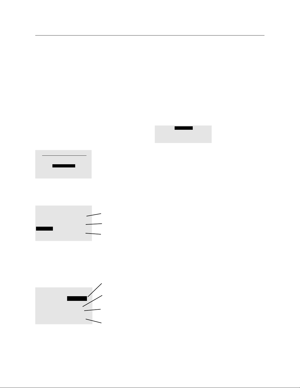
THE BLUE BOX LT PROGRAMMING 81
For more information on groups, please refer to the
Groups FAQ.
PROGRAMMING GROUPS
To Access a Group
Within the DTC, there are two paths you can use to
access a group for programming purposes:
From USER MENU:
Navigate to: USER MENU>GROUP LOADS 1.
and ENTER.
USER MENU
MANUAL OVERRIDE
REVIEW SCHEDULE
GROUP LOADS
PROGRAM SWITCH
SETUP MENU
SCROLL to the correct page. (1 through 6) and 2.
TAB to the desired GROUP. ENTER to begin
editing or creating the desired GROUP.
GROUPS PAGE 1-6
GROUP 1 UNUSED OFF
GROUP 2 UNUSED OFF
GROUP 3 USED MOM
GROUP 4 USED ON
GROUP 5 USED ON
GROUP 6 UNUSED OFF
This group does not
have any loads
Momentary Group
This Group has loads
and is on
After creating, exiting, and saving a schedule, TAB
DOWN once to NO LOADS, or GROUP X (X
represents a number 1-32). ENTER to edit or create
the GROUP.
To Edit a Group
1. SCROLL to select the desired GROUP Type.
GROUP1 MAINTAIN
EDIT: LCP-1 LOAD-1
Add or delete loads.3.
EXIT when complete.4.
TAB to a group and SCROLL up or down to change the
status. Enter to edit the group
From the SCHEDULE MENU:
Schedule 1 is
programmed and has
SCHEDULES PAGE 1-6
Name: SCHEDULE 1
SCH 1 ==> NO LOADS
SCH 2 UNUSED
SCH 3 UNUSED
SCH 4 ==> GROUP 4
SCH 5 UNUSED
SCH 6 ==> DISABLED
LCDBBP03Sept08
no loads
Schedule 3 is not
programmed
Schedule 4 is
programmed and
controls GROUP 4
Schedule 6 is
programmed, but is
disabled
Page 82

82 THE BLUE BOX LT PROGRAMMING
ADDITIONAL GROUPS PARAMETERS
To adjust Group Parameters such as Automatic On,
Group Timer, and Blink Warning, navigate to the
Group Parameters Screen:
USER MENU › GROUP LOADS.1.
SCROLL to the correct page and TAB select a 2.
Group to be edited).
TAB to MNTN + TIMER or MNTN + BLINK 3.
and ENTER to Group Parameters Screen.
or
TAB to MAINTAIN and SCROLL to MNTN
+ TIMER or MNTN + BLINK and ENTER to
Group Parameters Screen.
Automatic On/No Automatic On
AUTOMATIC ON (the default setting) means that
the Group will switch its relays on when the Group
is turned on. Example: Schedule 1 turns on Group 1
at 9:00AM. If AUTOMATIC ON is selected the relays
in Group 1 will all be switched on. AUTOMATIC ON
is recommended for large open areas, such as a sales
floor or open area office.
NO AUTOMATIC ON means that the group will
not automatically switch relays on when the group
is turned on. Example: Schedule 1 turns on Group
1 at 9:00AM. If NO AUTOMATIC ON is selected.
the relays in Group 1 will not be automatically
switched on. Instead relays are turned on by a local
digital control station. NO AUTOMATIC ON is
recommended for smaller offices which have local
digital control stations.
TAB to AUTOMATIC ON.1.
SCROLL to change to NO AUTOMATIC ON.2.
Relay/Group Timers
All relays in a Maintain + Timer or Maintained + Blink
group have an “after-hours” timer value when the
group is switched off (usually by a time schedule) the
timer duration can be adjusted.
TAB to MNTN + TIMER, and ENTER.3.
GROUP1 PARAMETERS
AUTOMATIC ON
SET TIMER
TAB to SET TIMER and ENTER to program 4.
the after-hours relay timers. This features allows
occupants to switch lights on if the Group is off,
but only for the timer duration. This is an energy
savings feature required by most energy codes.
TAB to the Hours/Minutes/Seconds display 5.
and TAB/SCROLL to set the Hours/Minutes
and Seconds of the after-hours timer. 2:00:00 is
usually recommended. This will determine how
long relays are allowed to be “overrided” to the
“on” state before the timer runs out.
TIMER SETTING
REGULAR TIMER MODE
30:59:59 H/M/S
BLINK ONE: 05:00 M/S
BLINK TWO DISABLED
“Blink Timer” is only displayed, in a Maintain+
Blink Group. The default setting of 5 minutes gives
occupants 5 minutes after a “blink” warning to activate
an override (Momentary On, Toggle, or Momentary
On) switch before lights are shut off.
If during that 5 minute period, an “on” button is
pressed, all relays controlled by that button will be
extended for the duration of the timer (02:00:00
for example), and will again blink at that end of that
period. This process repeats itself every time the
override switch is activated until the next scheduled
On Time.
TIMER SETTING
REGULAR TIMER MODE
30:59:59 H/M/S
BLINK ONE: 05:00 M/S
BLINK TWO DISABLED
After Hours Timer is
for all relays in this
Group - relays will be
in a Timer-Mode to
conserve energy
BLINK is only for
MNTN+BLINK group
LCDBBP03Sept08
Page 83

THE BLUE BOX LT PROGRAMMING 83
TAB to 05:00 and TAB and SCROLL to change 6.
the Blink Timer to select a new countdown. If a
double blink is desired, set the second timer.
Programming Tip: Blink timers work backwards
from the off time. So if the first blink is 05:00,
and the second blink is 04:55. Then the first blink
will be issued 5 minutes prior to shut off and the
second blink will be issued 5 seconds later.
EXIT twice when complete to return to the 7.
Groups screen (Load Summary).
TIMER SETTING
REGULAR TIMER MODE
02:00:00 H/M/S
BLINK ONE: 05:00 M/S
BLINK TWO: 04:55 M/S
GROUP FAqS
How do you manually turn on a group using the :Q
clock interface?
Go to the “Group Loads” screen, highlight the :A
group:
1. For a MOMENTARY ON group SCROLL UP
to turn the relays in that group on,
2. For a MOMENTARY OFF group SCROLL UP
to turn the relays in that group off,
3. For a MOMENTARY MIXED group SCROLL
UP to control the relays per the ON and OFF
programming within that group,
4. For any MAINTAIN group, SCROLL UP to
turn the group on and SCROLL DOWN to
turn the group off.
How do you tell if a relay has a timer and what :Q
timer value is on it?
If you check the relay properties screen for that :A
LCDBBP03Sept08
relay, it will say REGULAR TIMER MODE: followed
by a number, e.g. TIMER 00:20:00 H/M/S.
How do you tell if a relay timer is active?:Q
If the relay is on, the manual override screen will :A
show the normal ON square symbol with an
additional little “leg” on the bottom left corner,
like this:
Relay ON with no TIMER:
Relay ON in TIMER mode:
What does a MAINTAIN + BLINK group do?:Q
It is identical to a MAINTAIN + TIMER group, :A
with the only addition being that when you turn
a MAINTAIN + BLINK group OFF, the lights
will blink or flick, and then wait for a specified
amount of time before the relay turns off. This
time period is called the “Blink time out.” This
time period is set in the MAINTAIN + BLINK
group under “SET TIMER”.
How do you take a relay out of timer mode?:Q
Find out what MAINTAIN + TIMER or :A
MAINTAIN + BLINK group that relay is in, and
turn that group ON.
How can you tell if a relay has a “Blink Timer”?:Q
If you check the relay properties screen for :A
that relay, it will say BLINK One or BLINK Two:
followed by a number, e.g. BLINK One: 20:00
M/S.
How can you tell if a relay is in a blink warning :Q
time-out?
The manual override screen will show the relay :A
as being on with TWO little legs on the bottom
corners, as shown here:
Relay on with no BLINK or TIMER:
Relay in final BLINK Warning Timer :
What is the purpose of the “Blink time OUT”?:Q
It gives the occupants of the area a warning :A
that the lights are about to turn off. They can
extend the time that they have light by pushing
any button with a rapidly blinking LED. This is the
Page 84

84 THE BLUE BOX LT PROGRAMMING
indication that the lights are in Blink Time OUT.
Where are the two locations on the DTC that a :Q
relay timer can be viewed or programmed?
USER MENU > GROUP LOADS > TAB :A
to GROUP > ENTER to select >TAB to
MAINTAIN+TIMER or MAINTAIN+BLINK
>ENTER to select >.
USER MENU >SETUP MENU >SYSTEM
RESTRICTED (PASSCODE 900001) >RELAY
PROPERTIES >select BOARD >.
You create a new MAINTAIN group or add new :Q
relays to an existing MAINTAIN group and EXIT.
Upon re-entering the group, you notice it has
changed itself into MAINTAIN+TIMER. Why?
One or more of the relays in the group :A
are also in another MAINTAIN+TIMER or
MAINTAIN+BLINK group which has assigned
it or them a timer value. Since the timer value
is written into the relay properties, it is carried
over into the new MAINTAIN group.
How do you find out which group(s) a relay is in?:Q
Look in the “What & When Menu”: SETUP :A
MENU >SYSTEM SETUP MENU >WHAT
AND WHEN? >WHAT CONTROLS RELAYS.
Select the relay and press ENTER. Any groups
that the relay is in will be displayed.
How do you find out what is turning a group :Q
off or on?
Look in the “What & When Menu”: SETUP :A
>SYSTEM SETUP >WHAT AND WHEN?
>WHAT CONTROLS GROUPS. Select
the group and press ENTER. Any schedules,
photocells or switches that control that group
will be displayed.
What do you do to sync up the relays in a group, :Q
when some of them are on and some are off?
Go to the “group loads” screen and turn on :A
the group again using the SCROLL UP button.
If the group is already “ON” scrolling up will rereiterate the “ON” command.
What does MAINTAIN mean in reference to a :Q
wall switch?
It means that the switch concerned is a contact :A
closure switch like an ordinar y wall switch. When
one flips the switch UP the contacts close and
stay closed and the lights come ON. (They are
MAINTAINED that way.) When one flips the
switch down the contacts open and the lights
go off. Note that both making the circuit and
breaking the circuit (from the switch to the
contact input) causes the relay(s) to react.
What does MOMENTARY mean in reference :Q
to a switch?
It means that it is expecting a pulse as would be :A
received from a push button. The command is
executed on contact closure. The contact opening
does nothing.
How do you get rid of a group you don’t want :Q
to use anymore?
Go to the “GROUP LOADS” screen, highlight :A
the group and press the DELETE button.
What should you suspect is happening when you :Q
delete a group but the relays still have a timer?
Those relays are in another MAINTAIN+TIMER :A
or MAINTAIN+BLINK group which is forcing a
timer onto them.
What should you be careful never to do with :Q
MAINTAIN + TIMER or MAINTAIN + BLINK
groups?
Never have the same relay in more than one :A
MAINTAIN + TIMER or MAINTAIN + BLINK
group.
What does the “NO AUTOMATIC ON” setting :Q
in a MAINTAIN+TIMER or MAINTAIN+BLINK
LCDBBP03Sept08
Page 85

THE BLUE BOX LT PROGRAMMING 85
group do?
It makes it so that when you turn ON the group, :A
the relays don’t come on – only the group
status changes to ON and the relay timers are
disabled.
Why would someone want to use “NO :Q
AUTOMATIC ON”?
So they can take disable relay-timers without :A
actually turning the relays on. For example, if
the customer wants to turn lights on with a
switch early in the morning, and not have them
automatically shut off after an hour (timer
mode), they would need to turn the MAINTAIN
+ TIMER group on with a schedule. However, if
they don’t want the actual lights to turn on until
they use a switch, they would set the group to
“No Auto On”. This would take the relays out
of Timer mode, but not turn them on with the
schedule. This saves energy until someone enters
the room and switches the lights on.
When must a switch button be programmed :Q
to operate a group instead of just operating the
relays directly?
When you want the switch to operate more :A
than 8 relays, the system will require you to make
them into a group.
this is that switch buttons turn maintain groups
ON when the button is held down and OFF
when the button is released.
Having to hold the button down to keep lights
on is not generally useful!
If you are having a photocell control more than :Q
8 relays, what type of group would you assign to
the photocell?
You would normally use a maintain-type group. :A
Remember that only maintain-type groups can
be turned on AND off. If you want the photocell
to turn lights ON when it is dark and OFF when
it is bright, the easiest way is to use a maintain
group.
When would you use a momentary-type group :Q
with a photocell?
When you only want the photocell to turn the :A
relays OFF, or only want it to turn relays ON.
Even when using a schedule to turn the lights
off (for example at 11:00pm), one would usually
program the Photocell as “Maintain”. This ensures
the lights turn off at dawn in the event that an
override “ON” command switched the lights on
during the night.
How do you toggle a group on and off using a :Q
single switch button?
You can’t. Groups cannot be toggled. If you :A
want to turn more than 8 relays on and off
with a switch, you need to use two buttons and
two groups: one MOMENTARY On and one
MOMENTARY OFF.
What kind of group would you normally NOT :Q
LCDBBP03Sept08
assign to a momentary switch?
You normally do NOT assign any of the maintain-:A
type groups (MAINTAIN, MAINTAIN+TIMER,
MAINTAIN+BLINK) to a switch. The reason for
Page 86

86 THE BLUE BOX LT PROGRAMMING
OTHER SYSTEM / SET UP PROGRAMMING
Date, Time and Location
The DTC in the relay panel is astronomical, and
needs to know the date, time, and location.
enter new time/date
8:50:00 AM PAGE 1
27 June 2008 Fri
Time starts when
you... hit enter
assembled 3 jan 2008
To save your settings
TAB to here and
ENTER to select
In the DTC, navigate to: USER MENU > SETUP 1.
MENU > SYSTEM SET UP MENU > SET TIME
AND DATE.
TAB to the hour and SCROLL to select. Repeat this 2.
process for minutes, seconds, day, month and year.
TAB to “HIT ENTER” and ENTER to save 3.
settings.
To Set Location
In the DTC Clock navigate to USER MENU > 1.
SETUP MENU > SYSTEM SET UP MENU >
SYSTEM OPTIONS > SELECT LOCATION >
LIST OF CITIES.
SCROLL to select city or nearest city.2.
TAB to “HIT ENTER” and ENTER to save 3.
settings.
Detroit MI
latitude: 42 N
Longitude: 83 w
time zone:gmt-5
To accept the above
settings...hit enter
SCROLL to select
nearest city
To save your settings
TAB to here and
ENTER to select
The Time Zone is the number of hours negative or
positive from Greenwich Mean Time (GMT). For
example: the Nor th American Eastern Time Zone
is - 5 GMT, Central Time is - 6, Mountain Time is - 7,
Pacific Time is - 8, and Hawaii is -11.
DAYLIGHT SAvING TIME
The relay control panel will automatically adjust
its time setting forward and backward an hour to
account for Daylight Saving Time.
To disable Daylight Savings Time
Navigate to the Display Options screen: 1.
SETUP MENU > SYSTEM SETUP > SYSTEM
OPTIONS > DISPLAY OPTIONS.
TAB to Daylight Savings and SCROLL to select 2.
NO.
TAB to “HIT ENTER” and ENTER to save 3.
settings.
EXIT when complete.4.
Military Time: NO
Seconds Visible: YES
Daylight Savings: YES
Temperature F/C: F
RS-232 K-BAUD: 57.6
Modem mode: 0
Photocell mode: NEW
To save: HIT ENTER
Daylight Saving Time will now be disabled.
Optional: If you cannot find any cities within several
hundred miles of your location, EXIT and go to
LATITUDE – LONGITUDE. Use a dependable
resource (internet, etc.) to locate your exact Latitude
and Longitude.
LCDBBP03Sept08
Page 87

THE BLUE BOX LT PROGRAMMING 87
To Adjust Daylight Savings Change-Over dates:
Navigate to the Display Options screen: SETUP 1.
MENU > SYSTEM SETUP > SYSTEM OPTIONS
> DAYLIGHT SET UP.
Daylight parameters
Daylight starts on:
2nd Sun of Mar.
Daylight ends on:
1st Sun of Nov
:
TAB to each setting and SCROLL to select the 2.
proper value. Note A strict date-time system is
not used.
The DTC will set the time forward one hour on
the start date and backward one hour on the
end date.
EXIT when complete. All changes will be 3.
automatically saved.
kEYBOARD LOCk CODE
If you are responsible for maintaining and programming
the lighting control system, you may wish to prevent
others from making changes in the clock interface.
To do this, you can set a keyboard lock code that is
required to make any changes to schedules, groups,
switch programming, etc.
and TAB UP or DOWN to move between digits.
When the desired value has been entered, EXIT to
save the code and return to the previous menu.
Any user attempting to access the programming
interface will now be required to enter the code you
set in order to view or change settings.
To remove the keyboard lock code, navigate back to
the screen where the code was originally.
SETUP MENU > SYSTEM SETUP MENU > SYSTEM
OPTIONS > KEYBOARD LOCK CODE (set the
4-digit number to 0000 and EXIT).
To set up the keyboard lock code, navigate the
following menus:
KEYBOARD LOCK CODE
IS: 0000
Set Code ‘0000’ to
disable or any other
code to enable Key Lock
permanently
Hit exit if not sure
and see Users manual.
SETUP MENU > SYSTEM SETUP MENU > SYSTEM
OPTIONS > KEYBOARD LOCK CODE.
LCDBBP03Sept08
You will be prompted to create a 4-digit keyboard
lock code. SCROLL UP or DOWN to change values
Page 88

88 THE BLUE BOX LT PROGRAMMING
TIME SCHEDULE PROGRAMMING EXAMPLES
EXERCISE #1- CONTACT CLOSURE DEvICE
CONTROLLING 4 RELAYS
The client wants to have a Security System turn on
LCP1: 1-4 for the duration of an “Alarm Mode” event.
The Security System will issue a maintained closure
for the duration of the event through Input 1 of a
contact-closure interface. What do you do?
SOLUTION:
SWITCHES PAGE 1-2
#5: 14 BTN SW 5
#6: SWITCH 06
#7: SWITCH 07
#8: SWITCH 08
SWI ID05-1 MAINTAIN
EDIT: LCP-1 LOAD- 4
LCP1:1-4
Address 5 is a
14 Btn Input. Its
either the Blue
Box contact inputs
or a DigiLink
Select Maintain
(refer to Control
Types)
Add LCP 1: 1-4
Navigate to the DI card address (switch), and 1.
the input (button) you want to program (Refer
to Navigating to a Switch).
TAB to MAINTAIN and SCROLL to select 2.
Control Type. Maintain is probably the best
choice for a Security System (Refer to Control
Types).
TAB to LOAD. SCROLL and ENTER to select 3.
loads (Refer to Adding a Load).
EXERCISE #2 - CONTACT CLOSURE DEvICE
CONTROLLING 10 RELAYS
The same requirements as Exercise #1 but the
customer wants the security system to control 10
relays (LCP1 1-10) instead of four.
Follow the above steps adding more loads.4.
EXIT when complete.5.
Your selection is
more than 8 loads.
Proceed to create a
group?
No / Yes
The system
automatically
creates a Group
more than 8
loads.
TAB to YES and ENTER to save as a GROUP.6.
To determine the new Group name. TAB to the 7.
button and ENTER.
SWI ID05-1 GROUP 2
To edit the loads
you must use
the group menu
Button 1 controls
Group 2.
EXERCISE #3 - TIME SCHEDULES WITH
OvERRIDE SWITCHES
The client wants a time schedule for indoor lights
starting at 7:00 am and off at 5:30 pm.
After hours the digital switches can turn the lights
on but only for two hours. Also, the clients want to
warn occupants five minutes to prior shut-off. What
do you do?
SOLUTION:
Set up a schedule: ON: 7:00 AM & OFF: 5:30 PM.1.
SCH 4 EXCEPT NONE
EVERY DAY
ON TIME: 07:00 AM
OFF TIME: 05:30 PM
The schedule will control a MAINTAIN+BLINK 2.
group with a 2 hour timer, and 5 minute blink
warning. Select the relays for this group as
needed.
SCHEDULES PAGE 1-6
Name: SCHEDULE 1
SCH 1 ==> GROUP 1
SCH 2 UNUSED
SCH 3 UNUSED
SCH 4 ==> NO LOADS
SCH 5 UNUSED
SCH 6 ==> DISABLED
GROUP 4 MNTN+BLINK
EDIT: LCP-1 LOAD-1
LCP1:1-12
LCDBBP03Sept08
Page 89
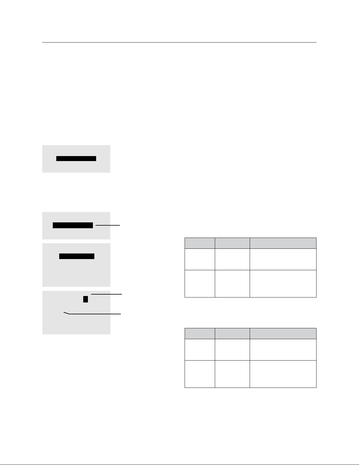
THE BLUE BOX LT PROGRAMMING 89
Tip: If you wish to prevent the lights from all coming
on at 7:00 am, select NO AUTOMATIC ON, and then
the local digital switches will turn the lights on and
the schedule will turn the lights off. (see Additional
Group Parameters) This is optimal for energy savings
when local digital switches are used.
GROUP 4 PARAMETERS
NO AUTOMATIC ON
TIMER OUT: 1:00:00 Hr
OFF SWEEP: 05:00 Mins
Program each switch button that will need to 3.
override lighting after-hours with a Toggle or On
Mode control type (refer to Control Types) and
add loads as appropriate.
SWITCHES PAGE 1-2
#5: 14 BTN SW 5
#6: OPEN OFFICE SW1
#7: OPEN OFFCE SW2
#8: RECEPTION
SELECT BTN SW ID#06
PAGE 1-1
B1: BUTTON 1
B2: BUTTON 2
B3: BUTTON 3
B4: BUTTON 4
B5: BUTTON 5
B6: BUTTON 6
SWI ID06-2 ON MODE
EDIT: LCP-1 LOAD-3
LCP1:1,3
Address 6 has
been named the
OPEN OFFICE
SW1.
Refer to
Navigation Tree
for the Naming
Menus
Select TOGGLE or
ON MODE (refer
to Control Types)
Add any relays in
the group
After-hours, all lights (loads) should be on a 2.
1-hour timer with a 5-minute blink warning.
Employees enter the store as early as 5:00am 3.
and need to switch on enough lights to clean
and stock the store (called the “entry level”)
without the complications of a timer.
Entry level lights are controlled by LCP1:1-7. All
remaining lights are controlled by LCP1:8-24
Programming Steps
For step-by-step instruction on how to program
these schedules, refer to the sections on adding a
load, Control Types, Groups, and time schedules.
Set up a Schedule: ON: 5:00 AM & OFF: 10:20 PM. 1.
Employees coming in any time after 5:00 AM can
switch-on lights manually. The relays will not be
in timer mode because the Group was switched
on at 5:00 AM with NO AUTOMATIC ON.
Name Controls Behaviors
On 5am
Off 10:20pm
Every Day
Schedule 4
Group 2
Entry Lights
Maintain + Blink
Group 2
LCP1:
Relays 1-7
NO Automatic On
1 Hour Timer
5 Minute Blink Warn
Set up a second schedule: ON: 8:45am & 2.
OFF:10:20pm to sweep-on the remaining loads
15 minutes before and 20 minutes after-hours
Tip: Remember, the smaller the zone of control of
each button the greater the energy savings.
EXERCISE #4 - RETAIL STORE
Information and customer requirements
LCDBBP03Sept08
Store hours: 9:00am to 10:00pm pm every day.1.
Lights should be swept-on 15 minutes before
store opening and off 20 minutes after closing.
Name Controls Behaviors
On 9:20am
Schedule 5 Group 3
Off 10:20pm
Every Day
Maintain + Blink
Group 3
LCP1:
relays 8-24
(Yes) Automatic On
1 Hour Timer
5 Minute Blink Warn
Page 90
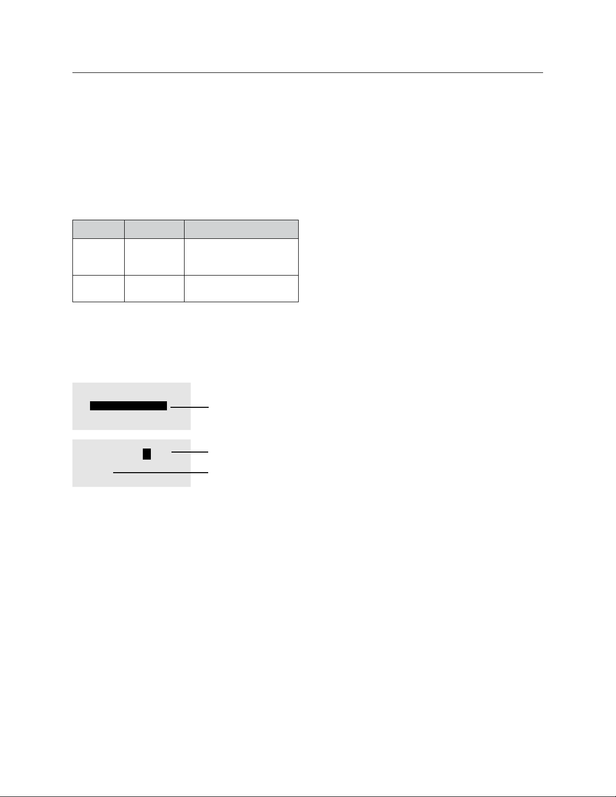
90 THE BLUE BOX LT PROGRAMMING
Set-up a third schedule to sweep-on the entry lights,
in case they were not manually switched on by a
control station. Note that this schedule simulates a
momentary push button and only turns the lights on.
Name Controls Behaviors
On 8:45am
Schedule 6 Group 4
Group 3
LCP1:
relays 1-7
Provide a button on a control station that 3.
switches on the “entry” lights on the morning
(On Mode).
Program another button on the same station to 4.
allow the last person out to switch off all lights.
Off 8:46Am
Every Day
Momentary On
SWITCHES PAGE 1-2
#5: 14 BTN SW 5
#6: ENTRY SWITCH
#7: SWITCH 07
#8: SWITCH 08
SWI ID06-2 ON MODE
EDIT: LCP-1 LOAD-8
LCP1:1-8
Address 6 has
been named
the Entry Switch.
(Refer to Naming
Switches).
Select ON MODE
(refer to Control
Types)
Add LCP 1: 1-7
A second control station in the managers office can
extend other lighting zones for after hours activities,
such as a photo-shoot, or extended store hours.
Tip: Check out our set-back Thermostats. They can
be locally and remotely programmed through the
Blue Box and can generate a very high Return On
Investment.
LCDBBP03Sept08
Page 91

®
™
THE BLUE BOX
SYSTEM
dIAGNOSTICS
TOOLS
LT
LCDBBSDT03Sept08
®
Lighting Control & Design
905 Allen Ave, Glendale CA 91201
Tel: 800-345-4448 • www.lightingcontrols.com
Page 92

92 THE BLUE BOX LT SYSTEM DIAGNOSTICS TOOLS
SYSTEM DIAGNOSTICS TOOLS
The DTC contains diagnostics tools which detect and
help narrow down any bus stability issues.
DIAL UP HOST
To test the operation of a modem, the “Dial up Host”
screen may be used to dial out to a cell phone or land line.
To do so, navigate to the Dial up Host screen:
USER MENU > SETUP MENU > RESTRICTED (PASSCODE 900001) > REMOTE SYSTEM MENU > DIAL UP
HOST
DIALING UP HOST
Enter the complete phone
number of the HOST and
hit ENTER.
On the screen, SCROLL UP to enter the first digit and TAB
DOWN to enter the next number. Enter the area code and
the phone number and ENTER to begin dialing out.
ERROR STATISTICS
This screen displays any kind of errors that may be accumulating on the bus. The “overall” errors field is the only
one of interest during general troubleshooting.
This screen must be monitored for approximately 3 minutes and if no errors accumulate, the bus is stable.
If errors accumulate in this field, there may be a bus stability issue and the “Bus splitting technique for a powered
bus” section at the end of this document may be used to
resolve the issue.
The fastest way to detect a bad device, missing, misplaced
terminator is to use the “Oscilloscope testing procedure”
in the O&M manual.
If an Oscilloscope is not available, complete all the steps in
the “System Start-Up & Cabling Guide” and refer to the
“Error Check” and troubleshooting sections at the back of
the document.
If all tests have passed and errors continue to accumulate,
contact Tech Support.
To navigate to this screen:
ERROR STATS. CLEAR
Overall: 0
Addr1: 0
Cmd0: 0
EEPROM FLAG ERR: 0
EEPROM WRITE ERR: 0
DROP-OFF: 0
FATAL-ERR: 0
USER MENU > SETUP MENU > RESTRICTED (PASSCODE 900001) > ADDRESSING-BUS SCAN > ERROR
STATISTICS
BUS SCAN
This screen displays all recognized devices on a bus. A relay panel displays the number “3” for every 8 or less relays
that it contains, any switch or photocell displays a “1”, and
any “Link-to” device such as Link-to-PC card displays a “2”.
The Blue Box LT 16 takes up 2 addresses.
If devices seem to appear and disappear intermittently on
the bus scan, the bus may be unstable. That is, if a switch is
assigned to address 7 and the display shows a “1”, then a
“0” and a “1” again, there may be a bad Cat. 5 or device in
that area of the bus. To navigate to this screen:
3000000000 0000000000
0000000000 0000000000
0000000000 0000000000
0000000000 0000000000
0000000000 0000000000
0000000000 0000000000
0000000 0-5 0
USER MENU > SETUP MENU > RESTRICTED (PASSCODE 900001) > ADDRESSING-BUS SCAN > BUS
SCAN DISPLAY
To find out which device or devices are appearing 1.
or disappearing, count up to the address(es) of the
device(s) and note it down.
Refer to the “System Device Schedule” in the master 2.
panel to find out the device type and location.
The next step would be to follow the Bus Splitting technique for a powered bus.
BUS MAP
Every device must be defined in the DTC under the Bus Map
LCDBBSDT03Sept08
Page 93

THE BLUE BOX LT SYSTEM DIAGNOSTICS TOOLS 93
SYSTEM DIAGNOSTICS TOOLS (Continued)
screen for it to be able to communicate with the rest of the
bus. A device may be assigned a “type” through this screen.
If a device takes more than one address, the first address must
be used to define the device type and the clock will automatically assign all (consecutive) addresses to the device.
The address assignment on the bus map must always
match the Bus Scan display. If they do not, errors will accumulate and devices may not function properly.
If more than one device is assigned the same address, there
may be address collisions that may be causing instability.
BUS MAP PAGE 1-19
ID1 : Panel LCP1
ID2 : Panel LCP1
ID3 : UNUSED
ID4 : UNUSED
ID5 : UNUSED
ID6 : UNUSED
ID7 : UNUSED
To check for collisions, refer to the “Scan by Serial Number” screen. To navigate to this screen:
USER MENU > SETUP MENU > RESTRICTED (PASSCODE 900001) > BUS MAP
SCAN BY SERIAL#
Scanning complete.
Found 3 items.
Not addressed: 0
Hit ENTER when ready.
USER MENU > SETUP MENU > RESTRICTED (PASSCODE
900001) > ADDRESSING-BUS SCAN > MORE DIAGNOSTICS > DEVICE MANAGEMENT > SCAN BY SERIAL #
BUS SPLITTING TECHNIqUE FOR A POWERED BUS
This method is slightly different from the one in the “Sys-
SCAN BY SERIAL NUMBER
When starting up the system, one of the steps includes
filling out the “System Device Schedule” with the help of
this screen. This screen displays the address, device type
and serial number of every device on the bus.
Additionally, this screen detects and displays any “overlapping addresses” or “address collisions” for the devices on
the bus. If more than one device is assigned the same address, a collision is displayed on this screen.
To view the serial#, device type and address of every device on the bus, highlight “ENTER” and press ENTER.
If any collisions are detected, the screen will display the serial number for any device that is colliding with the device
being viewed. One of these devices may then be assigned
LCDBBSDT03Sept08
a different address to eliminate the collision.
To navigate to this screen:
Page 94
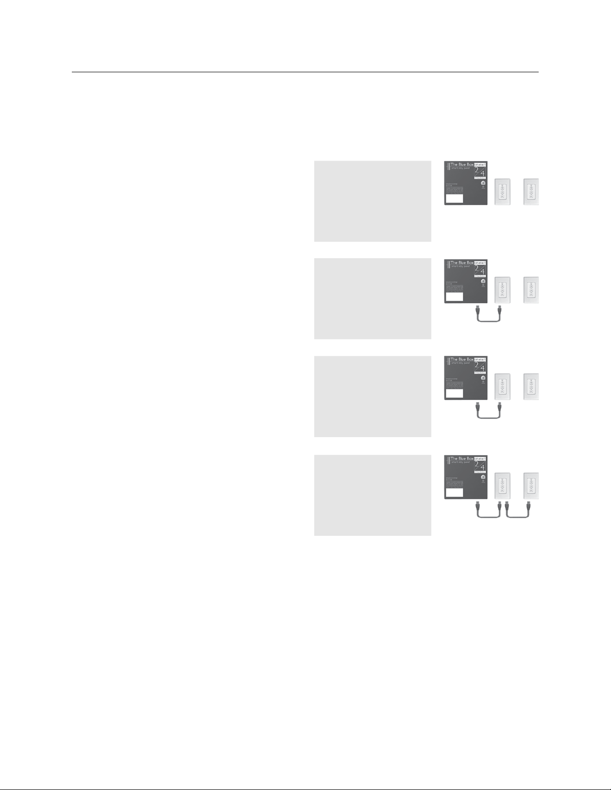
94 THE BLUE BOX LT SYSTEM DIAGNOSTICS TOOLS
tem Start-Up & Cabling Guide” in that, we have the added
advantage of being able to use the “System Diagnostics
Tools” mentioned above to help narrow or track down
the problem area.
The Error Checking Screens (Error Statistics and the Bus
Scan) must be checked after each of the following steps
for accumulating errors and for appearing and disappearing devices respectively.
Disconnect both Cat. 5 cables from the Blue Box LT 1.
master panel.
Add the Cat. 5 from the first device only on either side 2.
of the master panel and terminate both devices. Check
the Error Statistics and bus scan screen for errors.
If errors accumulate on either or both screens, lo-3.
cate the Cat. 5 cable connecting the device that was
just added to the bus and check for bad crimps, and
conduct a LAN cable test and plug it back in. TAB to
“Clear” and monitor both screens for errors for a
few minutes. If errors continue to accumulate, replace
cable, clear error count, and monitor both screens for
errors. If re-testing and replacing cables does not fix
the error counts, by-pass the device and add the next
device to the master panel.
Continue to add devices one at a time while moni-4.
toring for errors on both screens until the bad crimp,
cable, or device has been detected. Replace, retest
cables, or by-pass devices as needed.
ERROR STATS. CLEAR
Overall: 0
Addr1: 0
Cmd0: 0
EEPROM FLAG ERR: 0
EEPROM WRITE ERR: 0
DROP-OFF: 0
FATAL-ERR: 0
3000000000 0000000000
0000000000 0000000000
0000000000 0000000000
0000000000 0000000000
0000000000 0000000000
0000000000 0000000000
0000000 0-5 0
ERROR STATS. CLEAR
Overall: 0
Addr1: 0
Cmd0: 0
EEPROM FLAG ERR: 0
EEPROM WRITE ERR: 0
DROP-OFF: 0
FATAL-ERR: 0
ERROR STATS. CLEAR
Overall: 30
Addr1: 0
Cmd0: 0
EEPROM FLAG ERR: 0
EEPROM WRITE ERR: 0
DROP-OFF: 4
FATAL-ERR: 1
LCDBBSDT03Sept08
Page 95
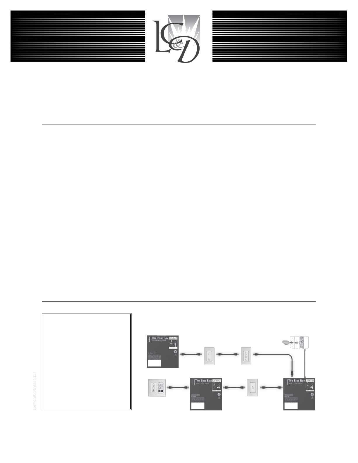
LCDBBSSU&CG03Sept08
®
THE BLUE BOX™ LT
SYSTEM START-UP & CABLING GUIdE
INSTRUCTIONS:
STEP 1:
Install all equipment and note down their serial numbers on
the
“System Device Schedule” in The Blue Box LT Master
Panel
......................(Refer to Installation Guides)
STEP 2:
Pull Cat. 5 cable in a daisy-chain between all digital devices.
Add “EZ” brand RJ45 connectors to cable ends and crimp
using the proper color code. Note:
switches or photocells until Step 5.
Do not connect contact
.............Pgs.96-97
STEP 3:
Test each cable with a LAN tester and once passed plug
each in. Do not power-up devices until Step 6! .....Pgs.97
Digital Network:
Locate multiple Blue Box LTs and
control stations where you need
them and then link them all with
Cat. 5 cable. One master panel
(with a Digital Time Clock) for 16
digital devices. Control stations
provide combined manual control
and after-hours override.
Note: The photocell is not on the
digital bus and should not be connected until Step 5.
Slave Relay Panel
Chelsea Digital Switch
STEP 4:
Verify proper connections and cabling using the Hardware
Activation Tests...................................Pg.98
STEP 5:
Make up low voltage cabling and connections for contact
closure devices or photocells. .... (See Installation Guides)
STEP 6:
Start-up and auto-address the digital bus. ......... Pg.99
Once the 6 steps are completed you can program schedules, switches, and photocells. Need help? Call Tech Support:
(800) 345-4448.
Outdoor Photocell
Slave Relay Panel
Master Relay Panel
Page 96
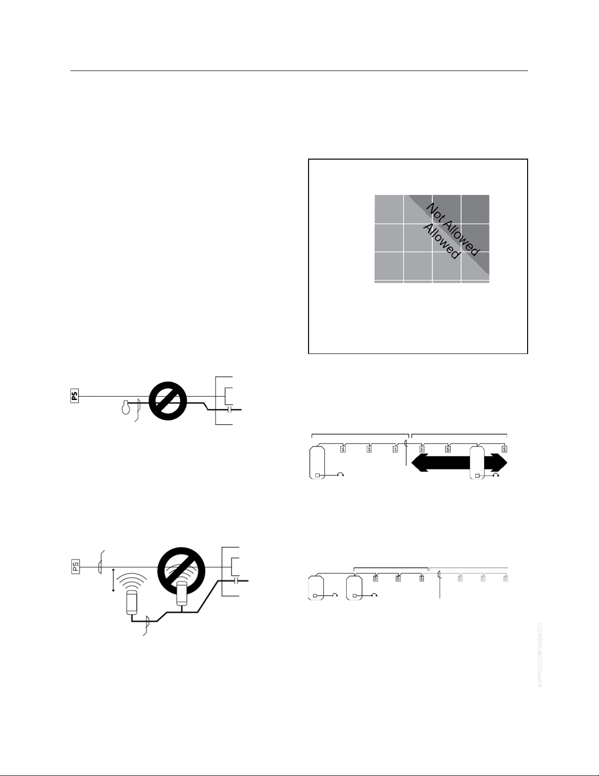
96 THE BLUE BOX LT SYSTEM START-UP & CABLING GUIDE
LCDBBSSU&CG03Sept08
LOW vOLTAGE CABLING
Digital devices have two RJ45 connectors and are daisychained using Cat. 5 (see cover). Non-digital devices (photosensors, toggle switches, etc.) are cabled per their installation guides (not daisy-chained).
Adhere to 568A or 568B standards for Cat. 5 cables.
!
Always use a dedicated pair for the center pins.
Refer to individual product installation guides for line-voltage cabling details and low voltage connection details Do
not “home run” digital switches back to a relay panel. No
spurs or T-Taps are allowed. Do not exceed 16 devices on
any system with a Blue Box LT Master.
ELIMINATE INTERFERENCE; ISOLATE CAT. 5
CABLES
…From Line Voltage Cable: Cat. 5 cable must be at least
12” from all line voltage conductors, except to cross or
make terminations.
Low Voltage Cable
Photosensor
Line Voltage Cable
Photosensor
Input
Relay
Relay Panel
Bus-Powered Devices Allowed
for Each Active Device
1000 ft.
900 ft.
800 ft.
700 ft.
Total Feet of Cable from
One Active Device
Number of Bus-Powered Devices
Active Device - Device with power supply (a transformer). It acts as a
source of electrical energy for the bus.
Bus-Powered Device - Any device that relies on the 12v supplied by the
bus for its power. Example: digital switches, and photosensor cards.
The more feet of Cat. 5 cable used, the fewer bus-powered devices before adding another active device.
Examples: Per the above char t, up to 3 bus-powered devices may be powered across 1,000 feet of Cat. 5 cable.
3
6
9
12
Low voltage cabling must not be run in parallel with
line voltage cable, and must not share the same conduit,
whether digital cable (Cat. 5) or low voltage cable (3#18
from a photosensor).
…From Line Voltage Devices: Low voltage cabling must avoid
EMF or RF from ballasts, arc welders or other “noisy” loads.
EMF or RF interference can create an unstable bus.
Low Voltage
Cable
Photosensor
12" or more
Line Voltage Cable
Photosensor
Input
Relay
Relay Panel
DON’T CAUSE vOLTAGE DROP!
There is a limit to how many switches and photocell cards
you can add in a row over long runs of Cat. 5 cabling.
Bus-Powered Devices
Power
Active Device
Cat. 5 Cable
Active Device Anywhere
in the 1000 ft. zone
Active Device
Power
The active device may be located anywhere within the
1,000 foot region.
Multiple active devices in the same location will not increase the distance allowed.
1000 ft. Insufficient Power
Power
Active Devices
Bus-Powered Devices
Power
Bus-Powered Devices
Cat. 5 Cable
For the above, the correct solution is to connect the active devices (relay panels) as the center of the network
and have two runs of cable. Call the Tech Support if cable
runs exceed 1000ft without active devices.
Page 97
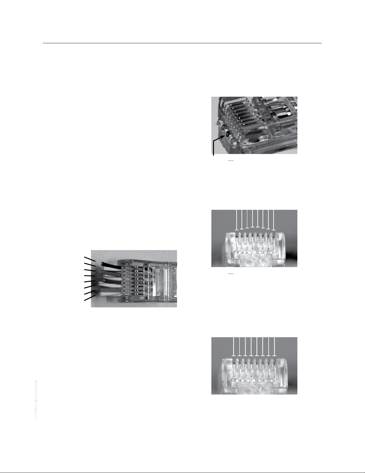
THE BLUE BOX LT SYSTEM START-UP & CABLING GUIDE 97
LCDBBSSU&CG03Sept08
MAkING UP Rj45 CONNECTORS
Never made up RJ45 connectors before? Its easy. Just follow the below steps. For a short lesson on making RJ45
connectors, refer to The Blue Box LT “O&M Manual”.
To be successful, only use the ratcheting crimping tool recommended by LC&D and a Local Area Network (LAN)
cable tester that allows remote testing — the ends of the
cable will be remote from each other.
Only use stranded Cat. 5 cable.
!
Only use EZ RJ45 connectors provided by Lighting
!
Control & Design (LC&D).
Remove two inches of the Cat. 5 jacket - use the 1.
wire stripper and cutter provided in our kit. Carefully
inspect the conductors for nicks.
Untwist all four pairs, and straighten/smooth out 2.
each conductor.
Reorganize the conductors in the order shown in the 3.
illustration below. Bring all conductors together until
they touch.
Contacts not seated properly (sticking out 1⁄16
of an inch too far).
Visually inspect each connector. Contacts should be 7.
pushed into the insulation of each conductor.
Repeat on the other end of the cable for a straight-8.
through cable.
Brown
Brown/White
Green
Blue/White
Blue
Green/White
Orange
Orange/White
Place an EZ connector on the end of the cable with 4.
the locking prong facing down.
Push conductors completely through and (using flush 5.
cutters or box cutters) trim-off all excess cable. Conductors should butt up to the end of the connector
– they must not protrude or be too short.
Always follow acceptable safety procedures when using a
!
sharp cutting tool. Tools
more hazards than sharp ones.
Using the recommended ratcheting crimp tool, crimp 6.
at least five times for the best possible connection.
must be sharp; dull tools cause
Contacts not seated properly (bowed crimping).
Test every cable for continuity with a LAN cable tes-9.
ter. While testing, wiggle and tug on each connector
to test for a solid crimp.
Never make “hot” RJ45 crimps (crimping the other end of
a cable that has been plugged into a powered device). This
can damage equipment.
Contacts properly seated (at crimping).
Page 98
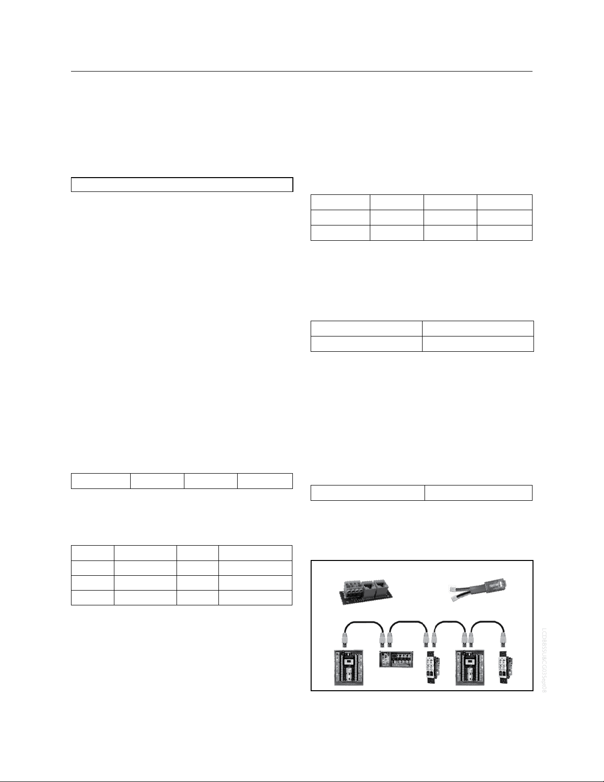
98 THE BLUE BOX LT SYSTEM START-UP & CABLING GUIDE
LCDBBSSU&CG03Sept08
HARDWARE ACTIvATION TESTS
Before starting, note total approximate bus cable length:
Once each cable has been checked with a LAN cable tester and plugged-in, it is still possible for the entire connected cable structure to become problematic. For instance,
dirt may accumulate inside the RJ45 sockets, the strain
on the Cat. 5 when pushing switches into the wall may
weaken connections or even break the conductors, or the
bus length may exceed 4000 ft.
Each test must be passed before moving onto the next. If
any readings are out of range, refer to “Hardware Activation Troubleshooting” section at the end of this document
or call Technical Support at 1-800-345-4448.
CONTINUITY TEST
This test is intended to verify bus length, continuity, and
detect crossed data-pair wires.
De-power every item on the bus and check the volt-1.
age at both ends to ensure a reading of 0vdc. Remove any terminators.
At one end of the bus, plug in the “Data/Power Jumper.” 2 .
At the other end of the bus, plug in the “Bus Checker Card” 3.
and measure resistance across the following terminals:
Gnd to A ____ohms B to +12 ____ohms
All test values must be within 10% of the values in the 4.
chart below to be considered valid!
Continuity Test Results (Gnd to A & B to +12)
Length Ohms Length Ohms
100 ft. 3 Ω to 6 Ω 2000 ft. 68 Ω to 80 Ω
500 ft. 12 Ω to 20 Ω 3000 ft. 102 Ω to 120 Ω
1000 ft. 34 Ω to 40 Ω 4000 ft. 130 Ω to 160 Ω
SHORT CIRCUIT TEST
This test is intended to detect any short circuits along the
bus. Please use the lowest resistance range (200 Ω) setting
on your multi-meter. DO NOT use a “beep” test.
Remove the “Data Power Jumper” and measure the 5.
resistance across the following terminals on the “Bus
Checker Card,”
All test values should be greater than 1K ohm! 6.
Gnd to A ____ohms A to B ____ohms
Gnd to B ____ohms A to +12 ____ohms
Gnd to +12 ____ohms B to +12 ____ohms
EARTH GROUND TEST
This test is intended to detect any pathways to earth
ground.
Measure resistance between the terminals mentioned be-7.
low, and “Earth ground” (a metallic enclosure or conduit).
Gnd A
+12 B
All readings between each terminal and “Ear th 8.
ground” should be infinite or “Open”!
TERMINATOR TEST
This test is intended to ensure that only 2 terminators
exist, one at each end of the bus. If the readings are out of
range, it would indicate a missing, misplaced, or an extra
terminator (terminators are shipped in the Master Panel).
Add a “Terminator” on the first and last device. On 9.
the “Bus Checker Card“, measure
A to B ____ohms
Test reading should be within 62 10.
Remove the bus checker card and call our Tech Sup-11.
port with your results at: 1-800-345-4448 x391.
Ω to 92 Ω!
Figure A:
Bus Checker Card
Data/Power Jumper
Page 99
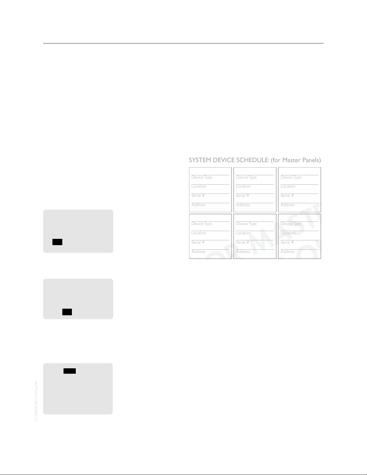
THE BLUE BOX LT SYSTEM START-UP & CABLING GUIDE 99
LCDBBSSU&CG03Sept08
Device Type
Location
Serial #
Address
Device Type
Location
Serial #
Address
Device Type
Location
Serial #
Address
Device Type
Location
Serial #
Address
Device Type
Location
Serial #
Address
Device Type
Location
Serial #
Address
Device Type
Location
Serial #
Address
Device Type
Location
Serial #
Address
SYSTEM DEVICE SCHEDULE: (for Master Panels)
(Master) LCP1
1
3 btn sw
Hallway
8875
3
6 btn sw
lobby
4685
4
DI-6
LCP 1
4055
7
LCP 2
telecom
af97
5
(Master) LCP1
elec rm
ce80
1
SYSTEM ACTIvATION
AUTO ADDRESS DEvICES
Starting up a new system requires a few simple steps.
Consider the following steps to set-up and start the system (see page 6 for DTC navigation).
1. After completing the Hardware Activation Tests, power
up all slave panels, and active devices (any device with
an onboard - 120 or 277 - power supply) first and then
power up the master panel. Check that the power-indicator LEDs on all digital devices are lit-up.
2. The main screen will be displayed for a few seconds, af-
ter which the “device detection” screen will be displayed.
TAB to YES and ENTER to auto-address devices.
Found 1 device on the
system that are not used.
Would you like to
auto-assign them?
YES / NO / ->
Never Ask Again
If the number of devices
detected do not match
the number of devices
present on the bus, proceed to trouble-shooting
section.
4. To view address assignments in the “Serial Number
Scan” screen TAB to YES and ENTER.
Assigned 1 device.
Review assignments by
scanning all serial
numbers?
YES / NO
The “Serial Number
Scan” screen displays the
serial number, address,
and device-type of added
device(s)
FILL OUT SYSTEM DEvICE SCHEDULE
6. In the “Serial#” field SCROLL to review each device
(including DI cards). If collisions are present or if two
devices share the same address, contact Tech Suppor t.
SCAN BY SERIAL#
SERIAL# CE80
ADR: 1
Item Type: Switch
Mapd: 6 Btn. Switch
Address OK
SAVE ADDRESS CHANGES
Fill out the “System Device Schedule” located on the back
of the “Panel Schedule” inside the master panel.
If unable to correlate the serial numbers and device locations when filling out the “System Device Schedule”, refer
to the serial label on each device or follow the “Read Address” section of the Blue Box LT “O&M Manual”.
ERROR CHECk
The system is now ready for Error Checking. Press EXIT
repeatedly to go back to the main menu.
7. Navigate to the “Error Statistics” screen. Use the path
USER MENU > SETUP MENU > RESTRICTED > ADDRESSING-BUS SCAN > ERROR STATISTICS. The
password to enter the RESTRICTED area is 900001.
8. TAB to the field that says CLEAR and press ENTER to
clear errors. If after 3 minutes no errors accumulate on
this screen, your system is stable.
9. If errors continue to accumulate refer to the Error
Check Troubleshooting section of the Blue Box LT
“O&M Manual” or call Technical Support for assistance
at 800-345-4448.
vERIFY DATE, TIME & LOCATION
To change the factor y programmed settings, refer to the
Blue Box LT “O&M Manual”.
Page 100
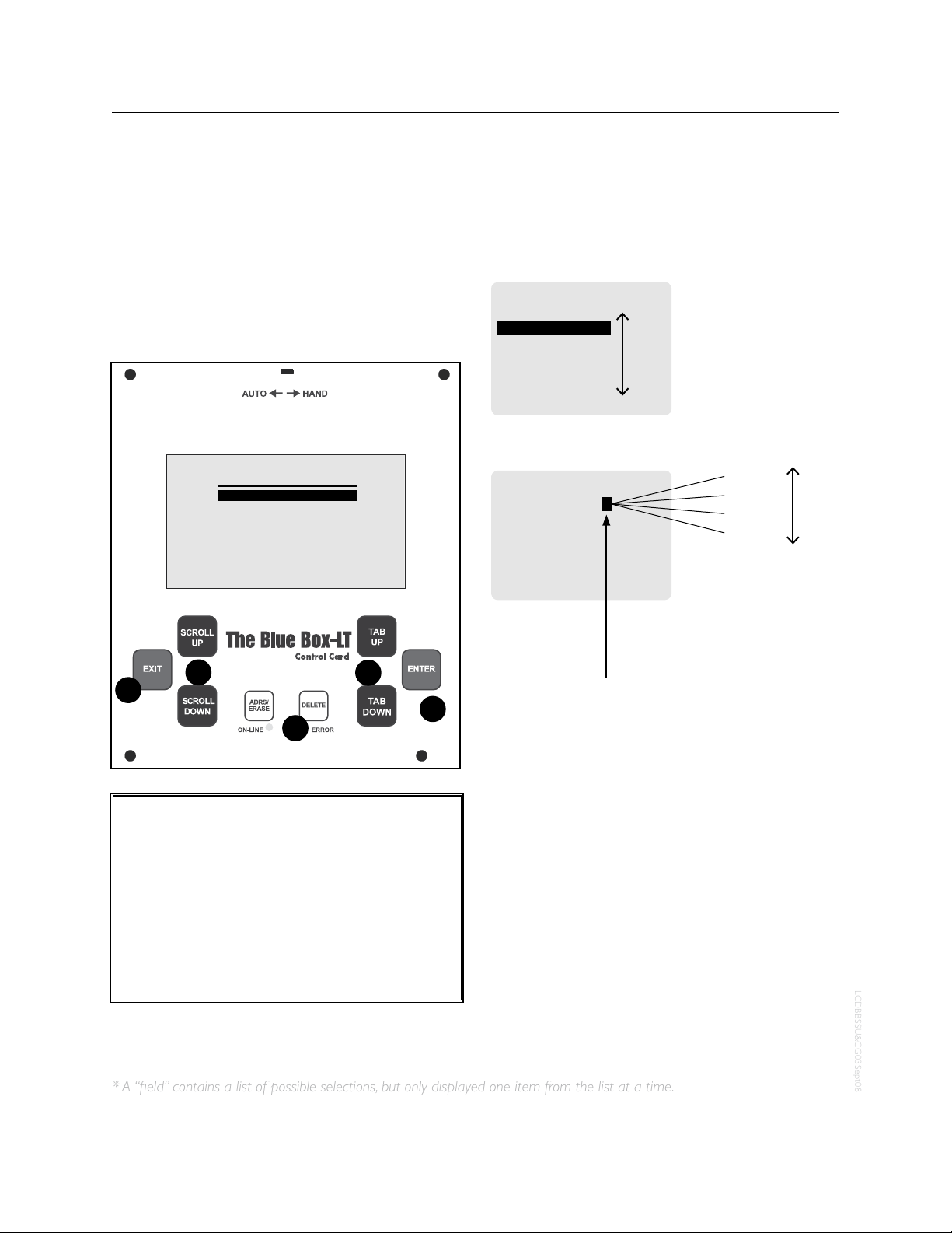
100 THE BLUE BOX LT SYSTEM START-UP & CABLING GUIDE
LCDBBSSU&CG03Sept08
DTC CLOCk NAvIGATION BASICS
Most devices can be programmed from the DTC
(Digital Time Clock) in the master Lighting Control
Panel (LCP).
USER MENU
MANUAL OVERRIDE
REVIEW SCHEDULE
GROUP LOADS
PROGRAM SWITCH
SETUP MENU
1
3
4
5
2
CALL OUT LEGEND:
SCROLL through choices in one fi eld*1.
TAB to position the cursor2.
DELETE information or programming about 3.
an item. Use caution.
ENTER to select4.
EXIT to leave a screen.5.
TAB moves the cursor through a screen
SWITCHES PAGE 1-1
#04: SWITCH 4
#05: SWITCH 5
#06: SWITCH 6
#07: SWITCH 7
#08: SWITCH 8
#09: SWITCH 9
#10: SWITCH 10
SCROLL to choose one item from a fi eld.*
SWI ID05-5 TOGGLE
EDIT: LCP-2 LOAD-1
Load 4
Load 3
Load 2
Load 1
This“ eld” contains a list of possible
selections, but only displays one item
from that list at a time.
TAB moves the cursor through a screen
SWITCHES PAGE 1-1
#04: SWITCH 4
#05: SWITCH 5
#06: SWITCH 6
#07: SWITCH 7
#08: SWITCH 8
#09: SWITCH 9
#10: SWITCH 10
SCROLL to choose one item from a fi eld.*
SWI ID05-5 TOGGLE
EDIT: LCP-2 LOAD-1
Load 4
Load 3
Load 2
Load 1
This“ eld” contains a list of possible
selections, but only displays one item
from that list at a time.
* A “field” contains a list of possible selections, but only displayed one item from the list at a time.
DIGITAL TIME CLOCk (DTC) NAvIGATION BASICS
DTC CLOCk NAvIGATION BASICS
Most devices can be programmed from the DTC (Digital
Time Clock) in the master LCP (Lighting Control Panel).
 Loading...