

GR 2400
BASIC PROGRAMMING GUIDE
Programming Guide Index
Introduction................................... 2
Navigation Basics.............................. 3
Programming a Digital Switch .................4
Adding or Deleting Loads...................... 5
Basic Photocell Settings...................... 6-7
Editing Time Schedules ........................ 8
Schedule Types & Trigger Events ...............9
Control Types & Group Types..................10
Programming Groups.........................11
This programming guide covers the basics—programming switches, schedules and photosensors. Other manuals
exist for more advanced programming issues. Call us if you have questions or need assistance during the
programming of your system. Technical Support: 800-345-4448
Important Note:
INTRODUCTION
Introduction: Almost all of the devices in the GR
2400 Lighting Control System are digital, meaning
they are part of a peer-to-peer network and can
be programmed. It is important to understand
from the outset that you eect almost any change
through programming alone.
This programming guide covers the basics—
programming switches, schedules and photocells.
Other manuals exist for more advanced
programming issues.
Additionally, help is only a call away. If equipped
with a modem, we can dial into your system and
program it for you, at no cost. Call us any time at:
(800) 345-4448.
Scroll
through
choices in
one eld
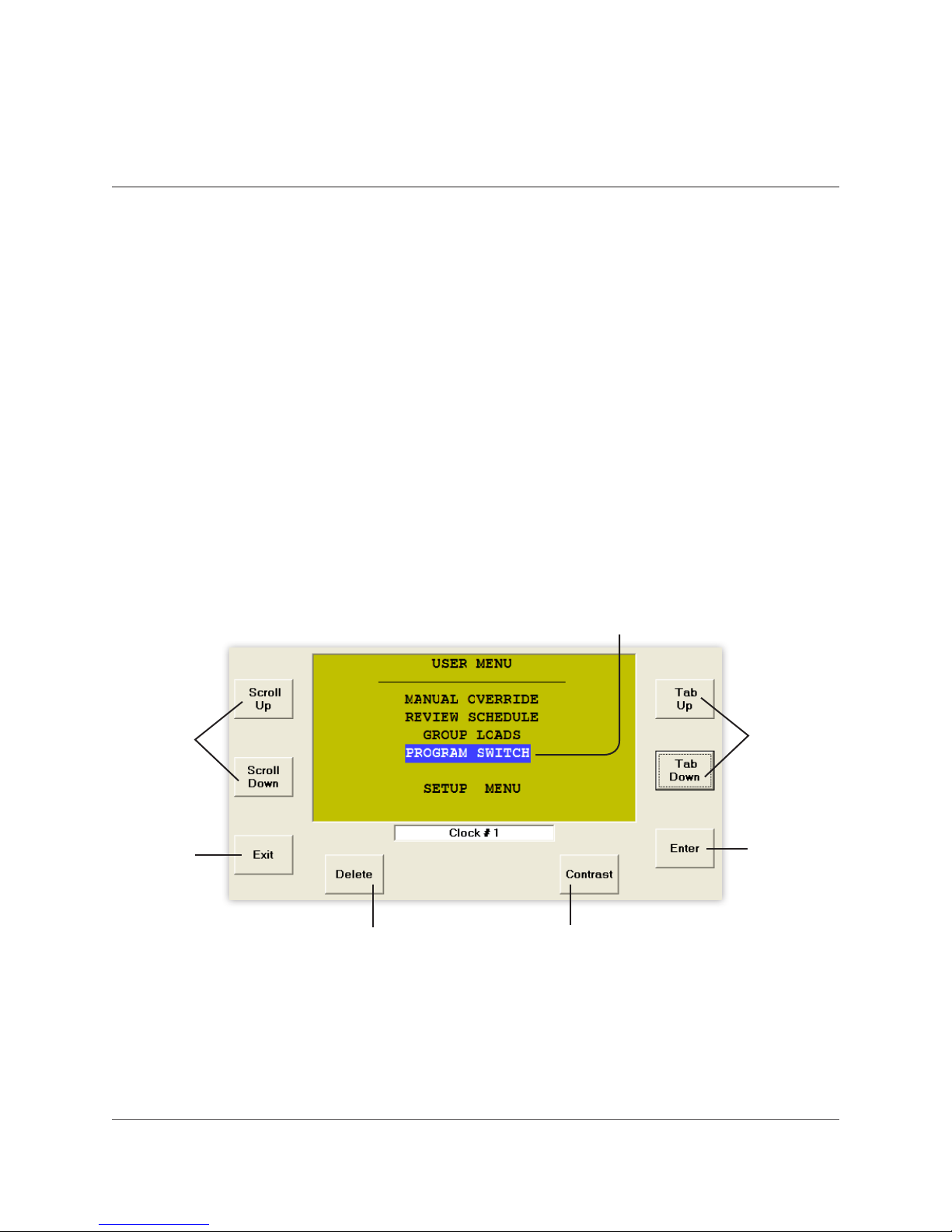
The DTC (Digital Time Clock): Most
programming is done from the DTC Clock (shown
below)/Programmer located in the master
Lighting Control Panel (LCP).
Virtual Clock or Unity Lighting Control software
allows remote connection via the internet or
modem to the DTC.
Cursor
Use to
position the
cursor
Exit out
of a menu
Deletes programming or
information about an item
(use with caution)
Pg. 2 www.lightingcontrols.com
Select an
item or
enter a
sub-menu
Increases/decreases
contrast of display screen
NAVIGATION BASICS
Menu: “Select a Switch”
SWITCHES PAGE 1-2
Tabbing: Use the TAB
buttons to move around the
display:
TAB
UP
or
TAB
DOWN
to position the cursor.
ENTER
#33: Reception
#52: Master Sw 1
#53: Master Sw 2
#59: Master Sw 3
#61: Hallway 100
#61: Hallway 200
#61: Hallway 220
To select the item or to drop into a new
sub-menu.
Scrolling: Use the SCROLL
buttons to choose one item
from a “eld”*:
SCROLL
UP
or
SCROLL
DOWN
to select items within a eld.
TAB
UP
or
TAB
DOWN
Sub-Menu: “Select a Button”
to exit the eld.
* A “eld” is a display in which one of many items
can be selected. In other words a value can be
changed by selecting a new one.
LC&D 800.345.4448 Pg. 3
MAINTAIN
TOGGLE
MIXED MODE
OFF MODE
ON MODE
GROUP 1
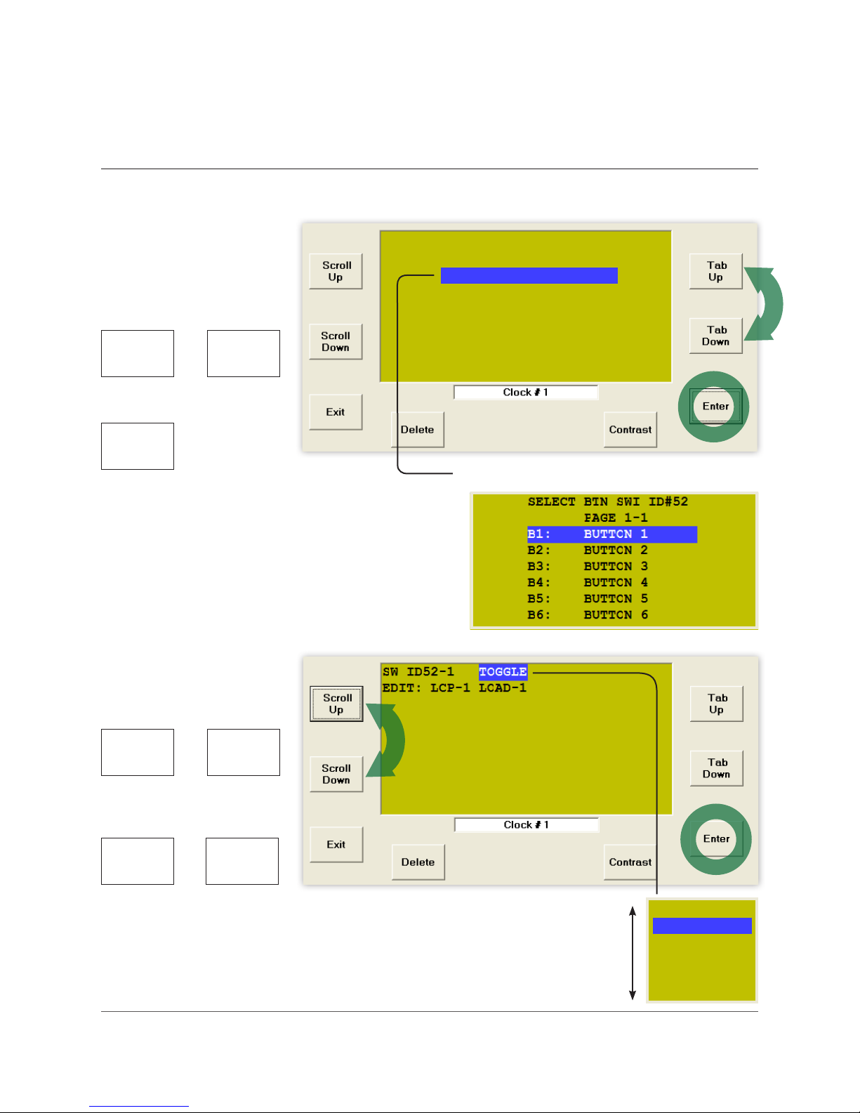
PROGRAMMING A DIGITAL SWITCH
To Start:
1. TAB to start.
2. TAB to Program Switch.
3. ENTER to select.
For Multiple Pages:
(more than 7 switches)
1. SCROLL to the correct page.
To Select Switch:
1. TAB to the correct switch.
2. ENTER to select.
USER MENU
MANUAL OVERRIDE
REVIEW SCHEDULE
GROUP LOADS
PROGRAM SWITCH
PROGRAM SWITCH
SETUP MENU
SWITCHES PAGE 1-2
#33: Ofce 101
#52: Ofce 102
#53: Ofce 103
#59: Ofce 104
#61: Ofce 105
#61: Ofce 106
#61: Ofce 107
SWITCHES PAGE 2-2
#63: Reception
#63: Reception
#64: Photocell North
#65: Photocell West
#66: Master Sw 3
#71: Hallway 100
#72: Hallway 200
#73: Hallway 220
PAGE 1-2
This indicates page
1 of 2:
If cursor starts here,
you have multiple
pages with switches
on each page. You
may need to navigate
to the correct page.
NOTE: Names can
be entered in the
naming menu (SETUP
MENU > SYSTEM
> SETUP MENU >
SYSTEM OPTIONS >
NAMING MENU). The
generated names are
usually displayed.
To Select Button:
1. TAB to the correct button.
2. ENTER to select.
Pg. 4 www.lightingcontrols.com
SELECT BTN SW ID#63
SETUP PAGE 1-1
B1: BUTTON 1
B1: BUTTON 1
B2: BUTTON 2
B3: BUTTON 3
B4: BUTTON 4
B5: BUTTON 5
B6: BUTTON 6
This indicates you
have selected switch
ID#63.

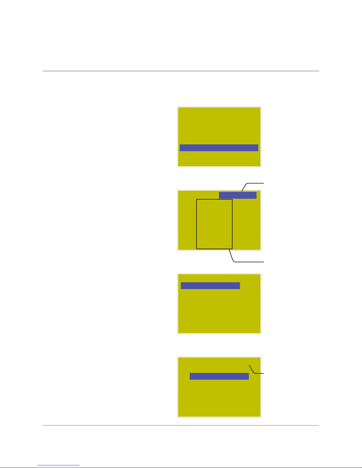
ADDING OR DELETING LOADS
Adding or deleting loads from a switch,
photocell, time schedule or group is always
done in the same way. Once you have
navigated to the correct Button, Trigger or
Group and before you add or delete loads, it is
important to determine the Control Type.*
1. SCROLL to select Control Type*.
2. TAB down to LCP 1.
For all Control Types (except Mixed Mode)*:
1. SCROLL to select LCP (1, 2, 3 etc.).
2. TAB to Load 1.
3. SCROLL to load you want to add or delete.
4. ENTER to select load—it will appear in the
Load Summary.
5. ENTER again to delete load.
6. Repeat to add or delete more loads.
7. EXIT up to Main Menu.
For Mixed Mode:
1. SCROLL to select LCP (1, 2, 3 etc.).
2. TAB to Load 1.
3. SCROLL to load you want to add or delete.
4. ENTER once to select Load On.
5. ENTER twice to select Load O.
6. ENTER three times to delete load.
7. Repeat to add or delete more loads.
8. EXIT up to Main Menu.
SWI ID63-1 MAINTAIN
EDIT: LCP-1 LOAD-1
SWI ID63-1 ON MODE
EDIT: LCP-1 LOAD-1
LCP1: 1
SWI ID63-1 ON MODE
EDIT: LCP-2 LOAD-3
ON LCP1: 1-3
OFF LCP2: 1-3
MAINTAIN
1
3
Indicates Control
Type*
(Refer to page 10
for information on
control types)
Indicates switch
ID#63, Button 1
Scroll selection eld
Load Summary,
indicates what
LCPs and loads
have already been
selected
Load Summary for
Mixed Mode shows
which loads will
be switched On
and which will be
switched O
To Delete a Load (from the Load Summary):
1. SCROLL to the load.
2. ENTER until the load is deleted (no longer in
the Load Summary).
* For more information about control types, please
refer to Control Types on page 10.
LC&D 800.345.4448 Pg. 5
SWI ID63-1 MIXED MODE
EDIT: LCP-1 LOAD-12
ON LCP1: 2-5,12
OFF LCP2: 1,4
12
To delete LCP1:12:
• SCROLL to LCP 1
• TAB to Load
• SCROLL to Load 12
• ENTER until deleted

BASIC PHOTOCELL SETTINGS
To Start:
1. TAB to start.
2. TAB to Program Switch.
3. ENTER to select.
For Multiple Pages: (more than 7 switches)
1. SCROLL to the correct page.
To Select a Photocell Card:
A Photocell Card is like a digital switch.
1. TAB to the correct Switch ID.
2. ENTER to select.
To Select Trigger:
Each Photocell Card has 14 Triggers, each
of which:
• may control its own set of loads
• may be programmed to switch loads on and
o at levels analogous to foot candles
1. If needed, SCROLL to the correct page for
Triggers higher than T6.
2. TAB to the correct Trigger.
3. ENTER to select.
4. SCROLL to Maintain.
5. ENTER to select the Trigger Level Menu.
USER MENU
MANUAL OVERRIDE
REVIEW SCHEDULE
GROUP LOADS
PROGRAM SWITCH
PROGRAM SWITCH
SETUP MENU
SWITCHES PAGE 1-2
#33: Ofce 101
#52: Ofce 102
#53: Ofce 103
#59: Ofce 104
#61: Ofce 105
#61: Ofce 106
#61: Ofce 107
SWITCHES PAGE 2-2
#63: Reception
#64: Photocell North
#64: Photocell North
#65: Photocell West
#66: Master Sw 3
#71: Hallway 100
#72: Hallway 200
#73: Hallway 220
SELECT BTN SWI ID#64
PAGE 1-3
T1: TRIGGER 1
T1: TRIGGER 1
T2: TRIGGER 2
T3: TRIGGER 3
T4: TRIGGER 4
T5: TRIGGER 5
T6: TRIGGER 6
SWI ID64-1 MAINTAIN
EDIT: LCP-1 LOAD-1
PAGE 1-2
MAINTAIN
This indicates Page
1 of 2
If cursor starts here,
you have multiple
pages with switches
on each page. You
may need to navigate
to the correct page.
This indicates you
have selected Switch
ID#64.
To access Triggers
above T6, SCROLL
the correct page
and then TAB to the
correct Trigger.
Select MAINTAIN as
the Control Type*.
Press ENTER to get to
Trigger Level Menu.
(For more than
eight loads, refer
to “Programming
Groups”).
Pg. 6 www.lightingcontrols.com

BASIC PHOTOCELL SETTINGS cont’d
To Program a Trigger Level:
Photocell Cards come with one or three
photocell inputs. Any of those photocells may
be used to control the Trigger.
1. If “Analog 1” is displayed, SCROLL to select
the desired photocell.
2. TAB to Time Delay.
3. SCROLL to select Time Delay.
LC&D recommends a minimum delay of 10
minutes to prevent lights cycling on and o.
SCROLL to select the desired Time Delay.
4. Tab to On Level.
5. Scroll to desired ON level.
LC&D recommends “30” as a starting point
for roof-mounted photocells facing north.
Contact LC&D for assistance.
6. Tab to O Level.
SENSOR ID#64-1
Analog 1:
Analog 1: 0050
Time Delay: TEST 5 Sec
On when light level
falls below: 0000
Off when light level
rises above: 0001
SENSOR ID#64-1
Analog 1: 0050
Time Delay: TEST 5 Sec
On when light level
falls below: 0000
Off when light level
rises above: 0001
SENSOR ID#64-1
Analog 1: 0050
Time Delay: TEST 5 Sec
On when light level
falls below: 0030
Off when light level
rises above: 0031
TEST 5 Sec
0030
“Analog” followed
by an integer (1,
2, 3) indicates this
is a PCC3 (3 Input
Photocell Card).
Analog without an
integer is a PCC1
(single input).
Refer to your
submittal document
for quantity and
location of photocells.
Time delay may be
1-30 minutes. Use the
TEST 5 SEC option
only when calibrating
the photocell.
Notice that the O
set-point cannot
go above the On
set-point.
7. Scroll to desired OFF Level.
LC&D recommends “40” as a starting point
for roof-mounted photocells facing north.
8. EXIT to Next Menu and refer to page 5 to
Program Loads.
LC&D 800.345.4448 Pg. 7
SENSOR ID#64-1
Analog 1: 0050
Time Delay: TEST 5 Sec
On when light level
falls below: 0030
Off when light level
rises above: 0040
0040
The O set-point is
always higher than
the On set-point.

EDITING TIME SCHEDULES
To Start:
1. TAB to start.
2. TAB to REVIEW SCHEDULE.
3. ENTER to select.
To Select the Schedule:
1. SCROLL to the correct page.
2. TAB to the correct Schedule (1-32).
3. ENTER to select.
To Select a Holiday List:
This portion of the menu allows you to select
from any pre-existing Holiday Lists. See below
to edit the Holiday List:
1. TAB to EXCEPT NONE.
2. SCROLL to desired Holiday Exception (if any).
3. TAB to the correct Schedule (1-32).
4. ENTER to select.
USER MENU
MANUAL OVERRIDE
REVIEW SCHEDULE
REVIEW SCHEDULE
GROUP LOADS
PROGRAM SWITCH
SETUP MENU
SCHEDULES PAGE 1-6
Name: SCHEDULE 1
SCH 1
SCH 1 UNUSED
SCH 2 UNUSED
SCH 3 UNUSED
SCH 4 UNUSED
SCH 5 UNUSED
SCH 6 UNUSED
SCH 1 EXCEPT NONE
EVERY DAY
EVERY DAY
ON TIME: 09:00 AM
OFF TIME: 05:00 PM
This indicates page
1 of 6.
Refer to page 11.
Add any Holiday
Exceptions.
To Edit Holiday Lists:
Two separate holiday lists may be created and
edited. Create custom holidays on “page 3.”
1. Follow this path: USER MENU > SETUP MENU
> SYSTEM SETUP MENU > EDIT HOLIDAYS.
2. SCROLL to select page.
3. TAB to the Holiday.
4. SCROLL to Yes to select.
Pg. 8 www.lightingcontrols.com
HOLIDAY LIST 1-PAGE 2
Date: Dec 25
Labour: NO
Columbus: NO
Veterans: NO
Thanks Giving: NO
Christmas: YES
Boxing: NO
YES

SCHEDULE TYPES & TRIGGER EVENTS
1. SCROLL to the desired schedule type.
Every Day (7-day schedule):
1. TAB to ON TIME and SCROLL to select Trigger
Event.
2. TAB to the hour and SCROLL to select.
3. TAB to minutes and SCROLL to select.
Mon-Fri, Sat, Sun:
1. TAB to ON TIME and SCROLL to select Trigger
Event.
2. TAB to the hour and SCROLL to select.
3. TAB to minutes and SCROLL to select.
4. Tab to each day set and repeat.
By Day (unique for each day):
This Schedule Type allows On and O times to
be edited to the nearest second, and allows a
schedule to start and end on specic dates.
1. Tab to desired day and ENTER to edit.
2. TAB to the hour and SCROLL to select.
3. TAB to minutes and SCROLL to select.
4. TAB to seconds and SCROLL to select.
To link other days to this schedule:
1. TAB to Every Day.
2. SCROLL to desired days or day sets and ENTER
to select.
3. EXIT to edit more days.
To select schedule start and stop date.
1. TAB to Jan and SCROLL to select.
2. Repeat to set start and stop dates.
To Exit this Schedule and Add Loads:
1. EXIT when complete.
2. TAB down once to edit the group and add
loads to this schedule (refer to Group Editing
Section).
SCH 1 EXCEPT NONE
EVERY DAY
EVERY DAY
ON TIME: 09:00 AM
OFF TIME: 05:00 PM
SCH 1 EXCEPT NONE
MONDAY - FRIDAY
ON TIME: 09:00 AM
OFF TIME: 05:00 PM
SAT ON DUSK+0:00
OFF DAWN+0:00
SUN ON NONE
OFF NONE
SCH 1
BY DAY H1 H2
Mo
Mo Tu We Th Fr Sa Su
ON TIME: 09:00:00a
OFF TIME: 05:00:00p
from Jan 1 to Dec 31
ON TIME: 9:00:00 am
OFF TIME: 5:00:00 pm
ADJUST THESE DAYS:
Mon
Every Day
Every Day
SCH 1
H1 H2
Mo Tu We Th Fr Sa Su
ON TIME: 09:00:00a
OFF TIME: 05:00:00p
from Jan 1 to Dec 31
TIME:
Jan
Schedule Type:
• EVERY DAY—7 day
schedule
• Mon-Fri, Sat, Sun
• BY DAY unique for
each day
Trigger Event:
• TIME means a
specic time of day
in hrs./mins.
• “DAWN (or DUSK) +
or -” means minutes
and seconds before/
after dawn or dusk
• NONE means none
This is the summary
of the Monday
Schedule.
This is the Edit
Schedule for Monday.
Link Other Days:
To save programming
time, link other days
using the same
schedule.
LC&D 800.345.4448 Pg. 9

CONTROL TYPES & GROUP TYPES
Control Types: ”Control Types” describes how loads are controlled.
TOGGLE Toggle up to 8 loads On or O.
ON MODE Up to 8 loads On only.
OFF MODE Up to 8 loads O only.
MIXED MODE
MAINTAIN
GROUPs (1-32)
Group Types: When controlling more then eight loads or when controlling any loads from a time
schedule, groups are required. GROUPS describe what loads are controlled and how they are controlled.
MOMENTARY ON “On Mode” more than 8 loads.
MOMENTARY OFF “O Mode” more than 8 loads.
MOMENTARY MIXED “Mixed Mode” more than 8 loads.
MAINTAIN
Also known as an “interlock”—this turns one set of loads On and
another set of loads O.
Loads are On during a closure and O when the closure is opened;
similar to a wall switch—used by photocells.
To control more than 8 loads, or when programming a time schedule,
always use GROUPs.
Used by time schedules and photocells controlling more than 8
loads. When the GROUP is On, the loads are On, and when the
GROUP is O, the loads are O.
MAINTAIN + TIMER
MAINTAIN + BLINK
Pg. 10 www.lightingcontrols.com
Usually used only with Time Schedules. When the GROUP is On,
the loads are On. When the GROUP is O, any switch controlling
any loads within the GROUP may only turn those loads On for a
programmed time.
Uses all of the features of the MAINTAIN + TIMER and adds a “blink
warning” prior to shutting loads o.

PROGRAMMING GROUPS
To Access the Group:
Within the DTC, there are two paths you can use
to access a group for programming purposes:
A) From USER MENU:
1. TAB to start.
2. TAB to GROUP LOADS.
3. ENTER to select.
B) From the SCHEDULE MENU:
1. EXIT schedule when complete.
2. TAB to NO LOADS.
3. ENTER to select.
1. SCROLL to select Group Type (see page 10
for selecting group types).
2. Add or delete loads (see page 5 for adding or
deleting loads).
USER MENU
MANUAL OVERRIDE
REVIEW SCHEDULE
GROUP LOADS
GROUP LOADS
PROGRAM SWITCH
SETUP MENU
SCHEDULES PAGE 1-6
Name: SCHEDULE 1
SCH 1 ==> NO LOADS
SCH 2 UNUSED
SCH 3 UNUSED
SCH 4 ==> GROUP 4
SCH 5 UNUSED
SCH 6 ==> DISABLED
GROUP 1 MAINTAIN
EDIT: LCP-1 LOAD-1
NO LOADS
MAINTAIN
SCHEDULE 1 is
programmed and has
no loads.
SCHEDULE 3 is not
programmed.
SCHEDULE 4 is
programmed and
controls GROUP 4.
SCHEDULE 6 is
programmed, has
loads, but is disabled.
Refer to page 10
for information on
Group Types.
NOTE: If using MAINTAIN + TIMER or MAINTAIN
+ BLINK, press ENTER when highlighted to set
parameters.
For more extensive data on programming the GR
2400 system, download the complete manual
from the CD that came with the system or from
www.lightingcontrols.com/downloads.
LC&D 800.345.4448 Pg. 11

Lighting Control & Design
9144 Deering Ave., Chatsworth, CA 91311
www.lightingcontrols.com
© 2007, 2009, 2010 Acuity Brands Lighting Inc., All Rights Reserved. • Form No. 1382.017
994-004-0022
 Loading...