

Page 1
Page 2

Introduction
I
1\11\1
Thank you for purchasing the Lightning Audio Amplifier.
Our customers have come
push the edge
els.
If,
that you see your Lightning Audio dealer. If you need further assistance, you can call us direct
at 1-888-881-8186. Be sure
purchase available when you call.
The serial number can be found on the outside of the box. Please record it
below
become useful
Serial Number:
Model Number:
DV
ATE
in
after reading your manual, you still have questions regarding this product, we recommend
as
your permanent record. This will serveasverification of your factory warranty and may
in
DR
the amplifier and woofer business with high value and high performance mod-
recovering your amplifier if itisever stolen.
DI!iII\lTE6RATE
to
expect that Lightning Audio pushes the edgeinaudio.
to
have your serial number, model number and the dated proof of
in
the space provided
Now
we will
Table
Introduction 2
Safety Instructions 2
Design Features
Installation 4-7
Installation Considerations 4
Mounting Locations 4
Battery and Charging 5
Wiring the System 5
Using Passive Crossovers 7
NOTE: Review each section for more detailed information.
Safety
of
Contents
Instructions
Operation
Adjusting Gain 8
3
Adjusting Crossover (X-Over) 8
Troubleshooting
Specifications 8
Limited Warranty Information 9
International
This symbol with "WARNING" is intendedtoalert the user to
LhWARNING
the presence of important instructions. Failure to heed the
instructions will result
in
severe injuryordeath.
This symbol with "CAUTION"isintended to alert the user to
LhCAUTION
the presence of important instructions. Failure to heed the
instructions can result
in
injury or unit damage.
Instructions
8
8
10
To
~
CAUTION:
prevent injury and damage to the unit, please read and follow the
instructions
system, not a headache.
~
CAUTION
If you feel unsure about installing this system yourself, have it
installed by a qualified Lightning Audio technician.
~
CAUTION
Before installation, disconnect the battery negative
vent damage
2
in
this manual.
to
the unit, fire and/or possible injury.
We
want you to have enjoyment from this
(-)
terminal to pre-
Page 3
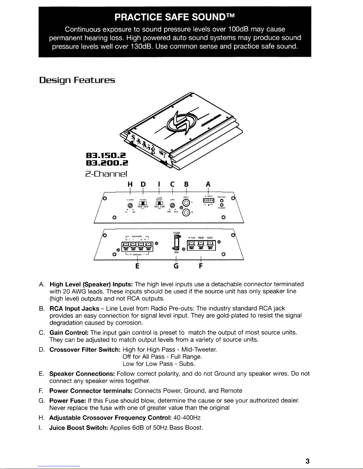
PRACTICE SAFE SOUNDTM
Continuous exposure to sound pressure levels over 100dB may cause
permanent hearing loss. High powered auto sound systems may produce sound
pressure levels well over 130dB. Use common sense and practice safe sound.
Design
Features
B3.1SD.i!
B3.i!OO.i!
2-Channel
H
0 C B A
~""
~
~
..
~
~
0 0
""""
~
$I~i!;:l$
o
L.
BRIOGEO·-.J
@L
~
ell
"~
.....
@R
JtfiiilO
3M
0
E
A.
High
Level (Speaker)
with 20 AWG leads. These inputs should be used if the source unit has only speaker line
(high level) outputs and not RCA outputs.
B.
RCA
Input
Jacks
provides
degradation caused by corrosion.
C.
Gain
They can be adjusted
D.
Crossover
E.
Speaker
connect any speaker wires together.
F.
Power
G.
Power
Never replace the fuse with one
H.
Adjustable
I.
Juice
an
easy connection
Control:
Connector
Fuse: If this Fuse should blow, determine the cause or see your authorized dealer.
Boost
The input gain control is preset to match the outputofmost
Filter
Connections:
Crossover
Switch:
Inputs:
- Line Level from Radio Pre-outs: The industry standard RCA jack
to
Switch:
terminals:
Frequency
Applies
The high level inputs use a detachable
for
signal level input. They are gold-platedtoresist the signal
match
Follow correct polarity, anddonot Ground any speaker wires. Do not
output
High for High Pass - Mid-Tweeter.
Off for All Pass - Full Range.
Low for Low Pass - Subs.
Connects Power, Ground, and Remote
of
6dBof50Hz Bass Boost.
levels from a varietyofsource units.
greater value than the original
Control:
40-400Hz
FG
connector
source units.
terminated
3
Page 4

Installation
INSTALLATION CONSIDERATIONS
The followingisa listoftools needed for installation:
Volt/Ohm Meter
Wire strippers
Wire crimpers
Wire cutters
#2
Phillips screwdriver
Battery post wrench
This section focusesonsome of the vehicle considerations for installing your new Amplifier.
Pre-planning your system layout and best wiring routes will save installation time. When
deciding on the layout of your new system, be sure that each component will be easily
accessible for making adjustments.
Lt.
CAUTION:
If you feel unsure about installing this system yourself, have it
Hand held drill w/assorted bits
1/8" diameter heatshrink tubing
Assorted connectors
Adequate
Adequate
Adequate Length-Black-Grounding Wire
Length-Red
Length-Remote
Power Wire
Turn-on Wire
installed by a qualified technician.
(-)
Lt.
CAUTION:
Before installation, disconnect the battery negative
terminal to
prevent damage to the unit, fire and/or possible injury.
Before beginning any installation, follow these simple rules:
1.
Be suretocarefully read and understand the instructions before attempting to install the unit.
2.
For safety, disconnect the negative lead from the battery prior to beginning the installation.
3.
For easier assembly, we suggest you run
4.
Route allofthe
5.
Use high quality connectors for a reliable installation and to minimize signal or power loss.
RCA
cables close together and away from any high current wires.
all
wires prior to mounting your unitinplace.
6.
Think before you drill!
hydraulic lines, vacuum lines or electrical wiring when working on any vehicle.
7.
Never run wires underneath the vehicle. Running the wires inside the vehicle provides the
best protection.
8.
Avoid running wires over or through sharp edges. Use rubber or plastic grommets to protect
any wires routed through metal, especially the firewall.
9.
ALWAYS protect the battery and electrical system from damage with proper fusing. Install
the appropriate fuse holder and fuse on the +12V power wire within 18" (45.7 cm)
battery terminal.
10. When grounding to the chassis
good, clean ground connection. Grounding connections should be
always be connected to metal that
Be
careful not to cut or drill into gas tanks, fuel lines, brake or
of
the vehicle, scrape
is
welded to the main body, or chassis, of the vehicle.
all
paint from the metal to ensure a
as
shortaspossible and
of
MOUNTING LOCATIONS
The mounting position of your amplifier will have a great effect on the sound performance
produced.
Engine Compartment
in
Never mount this unit
will void your warranty.
Trunk Mounting
the engine compartment. Mounting the unitinthe engine compartment
the
Mounting the amplifier vertically will provide the best cooling of the amplifier.
on
Mounting the amplifier
vertical mounting.
Mounting the amplifier upside down to the rear deck
and will severely affect the performance of the amplifier and
4
the floorofthe trunk will work but provides less cooling capability than
of
the trunk will not provide proper cooling
is
strongly not recommended.
Page 5

Installation
Passenger Compartment Mounting
Mounting the amplifierinthe passenger compartment will workaslongasyou provide a
of
sufficient amount
under the seat of the vehicle, you must have at least 1" (2.54cm) of air gap around the amplifier's
heatsink.
Mounting the amplifier with less than
passenger compartment will not provide proper cooling and will severely affect the performance
of the amplifier and
air for the amplifier to cool itself. If you
1"
(2.54cm)ofair gap around the amplifier's heatsinkinthe
is
strongly not recommended.
BATTERY AND CHARGING
are
going to mount the amplifier
Amplifiers will putanincreased loadonthe vehicle's battery and charging system.
recommend checking your alternator and battery condition to ensure that the electrical system
of
has enough capacity to handle the increased load
in
systems which are
Audio amplifier without problems, although battery and alternator life can be reduced slightly.
maximize the performance of your amplifier, we suggest the use of a heavy duty battery and
energy storage capacitor.
good condition should be able to handle the extra load of any Lightning
your stereo system. Stock electrical
We
WIRING THE SYSTEM
t CAUTION:
~
Lh
CAUTION: Before installation, disconnect the battery negative
If
you do not feel comfortable with wiring your new unit, please see
your local Authorized Lightning Audio Dealer for installation.
(-)
terminal
to
prevent damage to the unit, fire and/or possible injury.
t CAUTION: Avoid running power wires near the low level input cables, antenna,
~
1.
Plan
the wire routing. Keep
power cables and any high power auto accessories, especially electric motors. This
to prevent coupling the noise from radiated electrical fields into the audio signal. When
feeding the wires through the firewall or any metal barrier, protect them with plastic or rubber
grommets to prevent short circuits. Leave the wires long at this point to adjust for a precise
fit at a later time.
power leads, sensitive equipment or harnesses. The power wires
carry substantial current and could induce noise into the audio
system.
RCA
cables close together but isolated from the amplifier's
is
done
To
an
2.
Prepare the
insulation from the end of the wire. Insert the bared wire into the
set screw to secure the cable
NOTE: The B+ cable MUST be fused 18" or less from the vehicle's battery. Install the fuseholder
under the hood and prepare the cable ends
tight.
3.
Trim
the
end of the wire.
4.
Strip 1/2" from the battery end of the power cable and crimp a large ring terminal to the
cable. Use the ring terminal to connect to the battery positive terminal.
fuse
at
5.
Prepare the BLACK wire (Ground cable) for attachment to the amplifier by stripping 1/2" of
insulation from the end of the wire. Insert the bared wire into the
the set screw to secure the cable
from the metal surface and thoroughly clean the area of
end of the wire and attach a ring connector. Fasten the cable to the chassis using a nonanodized screw and a star washer.
RED
wire (power cable) for attachment to the amplifier by stripping 1/2" of
RED
wire (power cable) within 18"ofthe battery and strip 1/2"of insulation from the
this time.
B+
terminal and tighten the
in
place.
as
stated above. Connections should be water
DO NOT install the
GND
terminal and tighten
in
place. Prepare the chassis ground by scraping any paint
all
dirt and grease. Strip the other
5
Page 6

Installation
6.
Prepare the
from the wire end. Insert the bared wire into the
secure the cable into place. Connect the other endofthe
positive source. The switched voltage is usually taken from the source unit's accessory lead.
If the source unit does not have this output available, the recommended solution is
mechanical switch
REM
turn-on wire for connectiontothe amplifier by stripping 1/2"ofinsulation
REM
terminal and tighten the set screw
REM
wiretoa switched 12 volt
in
line with a 12 volt sourcetoactivate the amplifier.
to
to
wire a
7. Securely mount the amplifier
amplifier on cardboard
to
the vehicleoramp rack. Be careful nottomount the
or
plastic panels. Doing so may enable the screwstopullout
the panel duetoroad vibrationorsudden vehicle stops.
8. Connect the source signal
to
the amplifier by plugging the RCA cables/high level inputs into
the input jacks at the amplifier.
9. Connect the speakers. Strip the speaker wires 1/2" and insert into the speaker terminal
to
and tighten the set screw
DO
NOT chassis ground anyofthe speaker leads as unstable operation may result.
10. Perform a final check
of
secure into place. Be suretomaintain proper speaker polarity.
the completed system wiringtoensure that all connections are
accurate. Check all power and ground connections for frayed wires and loose connections
which could cause problems.
NOTE: Follow the diagrams for proper signal polarity.
& CAUTION:
These amplifiers are not recommended for impedance loads below
2 Q stereo and/or 4 Q bridged (mono).
& CAUTION:
Use only one input configuration. Using both the RCA and High Level
inputs will cause undesirable operation.
Power
Connection
-----;.;;;.;;;;;;;;;;=;;;;l,--
~~~;;.;;.,
ConnecttoSource unit's
accessory lead or
switched 12v source
from
Connect
_ chassis
-ofvehicle*
NEG
Vehicle Battery
2-Channel
~9
c:u:u::t
-_..
'Io,,;:··=·=;;....;;,i..;;Cl;;;;...;;;«D,.«D~~;;;;...;;;-~-.=.-~-;;;;...;;;Cl~.
~;<.,
RCA
Inputs
4Q
-~"-------''-'"~-----~
L.--lIIlIl-ro~
min.
Source
Unit
-~l==~
c:.
*5eeNoteBelow
~
I==~
(L+)Green~
(L-) Green/Black
(R+)
Gray :
(R-) Gray/Black :
- - -~:
, ,
, ,
, ,
, ,
,
.
:
1_--------------------------
---
-----------
*Keep Groundsasshortaspossible
--------~
-- --
--
- -
--
------
----
---
1
1
.
to
ground
~_mplifier
,
1:";'":.1
"0"
'OW,"
©J
0
+L-••R.
High
Level ©
nput
6
Page 7

Installation
*NOTE: When using High Level Inputs, if audible engine noiseispresent, connect the Black
wire
to
chassis ground. If noiseisstill present, contact your local authorized dealer or
Lightning Audio customer service.
USING PASSIVE CROSSOVERS
A passive crossoverisa circuit that
uses capacitors and/or coils and
placed
amplifier and speaker. The crossover
delegates a specific range
frequencies to the speaker for
optimum driver performance. A
crossover network can perform one of
three functions: High-Pass
(capacitors), Low-Pass (inductors or
coils)
capacitor and coil).
The most commonly used passive
crossover networks
systems. These
and require one component per filter.
Placing this filter
circuit will reduce power
speaker by 6dB/octave above or
below the crossover point depending
on whether it
pass filter. More complex systems
such
can cause impedance problems if not
professionally designed.
Passive crossovers
dependent upon the speaker's
impedance and component value for
accuracy. When passive crossover
components
speaker systems, the crossover's
effect
be taken into consideration along with
the speaker's impedance when
determining amplifier loads.
on
speaker leads between the
of
and
Bandpass (combination of
are
6dB/octave
are
easytoconstruct
in
series with the
to
is
a high-pass or low-
as
12dB/octave or 18dB/octave
are
directly
are
usedinmultiple
on
the overall impedance should
is
the
6dB/Octave
Freq.
Hertz
2 OHMS 4 OHMS
e
80 4.1mH
100 3.1mH
130 2.4mH
200 1.6mH
260 1.2mH
400 .8mH
.31mH
.08mH
more
.5mH
information,
600
800 .41mH
1000
1200 .25mH
1800 .16mH
4000
6000 51mH
9000 34mH
12000 25mH
For
---jf-
_-===----'1
Low-Pass
6dB/Octave
Speaker Impedance
m
1000IJF
800IJF
600IJF
400IJF
300IJF
200IJF
136IJF
100IJF
78IJF
66IJF
44IJF
20IJF
14IJF
9.51JF
6.61J
L =
C
= High-Pass (Capacitor)
e
8.2mH
6.2mH
4.7mH
3.3mH
2.4mH
1.6mH
1.0mH
.82mH
.62mH
.51mH
.33mH
.16mH
.10mH
68mH
F
51mH
Low-Pass
see
Audio
Dealer.
m
500IJF
400IJF
300IJF
200IJF
150IJF
100IJF
68IJF
50IJF
39IJF
33IJF
22IJF
10IJF
6.81JF
4.71JF
3.31JF
(Inductor)
your
Authorized
J
m
High-Pass
80HMS
e
16mH
12mH
10mH
6.8mH
4.7mH
3.3mH
2.0mH
1.6mH
1.2mH
1.0mH
.68mH
.33mH
.20mH
.15mH
100mH
1'
'.IT.0:
I'~'i
J~.I:
"~
m
250IJF
200IJF
150IJF
100IJF
75IJF
50IJF
33IJF
26IJF
20IJF
16IJF
10IJF
5IJF
F
3.31J
2.21JF
1.61JF
Lightning
+CAUTION: The Lightning Audio amplifiers
L..U. loads below 2n stereo and 4 n bridged (mono) loads.
are
not recommended for impedance
7
Page 8

Operation
ADJUSTING GAIN
To
adjust the gain setting, turn the amplifier gains all the way down. Turn the source unit volume
up until distortion is audible and then turn it
the amplifier gain setting until once again distortion is audible and then back it down until the
distortion is inaudible.
NOTE: For a more in depth setting procedure, contact Lightning Audio Technical Support.
down
a bit until the distortionisinaudible. Next, turn
ADJUSTING CROSSOVER {X-OVER}
Turn the crossover adjustment knob all the way down. With the system playing at normal
listening level, turn the crossover adjustment knob up slowly until the desired crossover point is
achieved.
Troubleshooting
Symptom
Amplifier does
turn
on.
Amplifier Noise
(Turn-On Pop)
Engine Noise
not
Diagnosis
B+orREM
15.5 volts ornovoltage present and wiring
Amplifierisnot properly grounded. Check wiring
Voltage spike from source unit
entering amplifier's input terminalifpops
Noiseisradiating into signal cables
not between 10.5 and Check the alternator, battery, fuse,
Specifications
B3.150.i!!
• Maximum Power: 450 watts
• Power Rating: 50w x 2 @ 40hms
75w x 2
150w x 1
• Input Sensitivity: 100mV - 5V
• High Level Input: 1.5V - 10V
• Signal to Noise Ratio: > 70dSA
• Channel Separation: 50dS
• Crossover: High/Low/All Pass switch
• Crossover Type: Variable
• Amplifier Fuse Value: 25Amp
• Chassis Size: 2"H x 11.1"W x
@ 20hms
@ 40hms
40-400Hz
(1)
7"0
Remedy
and
repairasnecessary
and
repairasnecessary
is
Connect turn-on module to
are
eliminated with
no
input signal to amplifier
Re-route signal cables away from
sources of high current
REM
B3.i!!OO.i!!
• Maximum Power: 600 watts
• Power Rating: 75w x 2 @ 40hms
100w x 2
200w
• Input Sensitivity: 100mV - 5V
• High Level Input: 1.5V - 10V
• Signal to Noise Ratio: > 70dSA
• Channel Separation: 50dS
• Crossover: High/Low/All Pass switch
• Crossover
• Amplifier Fuse Value: 30Amp
• Chassis Size: 2"H x 11.1"W x
@ 20hms
x 1 @ 40hms
Type:
Variable
40-400Hz
(1)
7.5"0
Specifications subject to change without notice
8
Page 9

Limited
Warranty
Information
Lightning
Audio
offers a limited warranty on
productsonthe
following terms:
• LengthofWarranty
Speakers
One year parts and labor warranty. Requires proof of purchase.
Amplifiers
One year parts and labor warranty. Requires proof of purchase.
Bolt: One year parts and labor warranty. Requires proof of purchase.
Strike and Storm: One year parts and labor warranty. Requires proof of purchase.
Or,
CT-1
Two years parts and labor warranty if installed by a Authorized
andPC2
One
year parts and labor warranty. Requires
proofofpurchase.
Dealer.
Requires proofofpurchase.
• What is Covered
This warranty applies only to Lightning Audio products sold to consumers by Authorized Lightning Audio
Dealers
Authorized Lightning Audio Dealerinanother country
not by Lightning Audio.
in
the United StatesofAmerica or its possessions. Product purchased by consumers from
are
covered only by that country's Distributor and
an
• Who is Covered
This warranty covers only the original purchaserofLightning Audio product purchased fromanAuthorized Lightning Audio Dealer
Lightning Audio with a copy of the receipt stating the customer name, dealer name, product purchased
and date
• Products found to be defective during the warraflty period will be repaired or replaced (with a product
deemed
of
purchase.
to
be equivalent) at Lightning Audio's discretion.
in
the United States.Inordertoreceive service, the purchaser must provide
• What is Not Covered
1.
Damage caused by accident, abuse, improper operations, water, theft, shipping
2. Any cost or expense related to the removal or reinstallation of product
3. Service performed by anyone other than Lightning Audio
4.
Any product which has had the serial number defaced, altered, or removed
5. Subsequent damage to other components
6.
Any product purchased outside the U.S.
7.
Any product not purchased fromanAuthorized Lightning Audio Dealer
or
an Authorized Lightning Audio Service Center
• Limit on Implied Warranties
Any implied warranties including warranties of fitness for use and merchantability
the periodofthe express warranty set forth above. Some states do not allow limitations on the length
an
implied warranty, so this limitation may not apply. No personisauthorized to assume for Lightning
Audio any other liability
•
•
HowtoObtain Service
Please call 1-888-881-8186 for Lightning Audio Customer Service.
Authorization number) to return any product
product
Mark
This product meets the currentEUwarranty requirements, see your Authorized dealer for details.
to
Lightning Audio. Always include ProofofPurchase.
RA#onoutsideofshipping carton.
EU
Warranty
in
connection with the sale of the product.
to
Lightning Audio.
You
You
must obtainanRA# (Return
are
responsible for shipment of
are
limitedinduration
to
of
Ship to:
Electronics
Lightning Audio
Warranty Repair Department
E.
2055
5th Street
Tempe, AZ 85281
RA#:
-------------
Ship to: Speakers
Lightning Audio
Speaker Returns
3056 Walker Ridge
Walker,
MI
49544
RA#:
Dr.
Suite G.
9
Page 10

09/058.M.
1230-52315-02
Printed
in
China
 Loading...