

Lighthouse Remote 3014PN, Remote-4 PN, Remote 3104PN, Remote 5014PN, Remote 5104PN Operating Manual


00

Lighthouse Worldwide Solutions
REMOTE-4 PN Series Airborne Particle Counter
Operating Manual

Copyright © 2007-2014 by Lighthouse Worldwide Solutions. All rights reserved. No part of this
document may be reproduced by any means except as permitted in writing by Lighthouse
Worldwide Solutions.
The information contained herein constitutes valuable trade secrets of Lighthouse Worldwide
Solutions. You are not permitted to disclose or allow to be disclosed such information except as
permitted in writing by Lighthouse Worldwide Solutions.
The information contained herein is subject to change without notice. Lighthouse Worldwide
Solutions is not responsible for any damages arising out of your use of the LMS program.
REMOTE 3014PN™, REMOTE 5014PN™, REMOTE 3104PN™, REMOTE 5104PN™ and
LMS™ are trademarks of Lighthouse Worldwide Solutions.
Microsoft
®
, Microsoft Windows™ and Excel™ are trademarks of Microsoft Corporation.
LWS Part Number 2489083317-1 Rev 4

EU DECLARATION OF CONFORMITY
Manufacturer’s Name: Lighthouse Worldwide Solutions, Inc.
Manufacturer’s Address: Lighthouse Worldwide Solutions, Inc.
1221 Disk Drive
Medford, OR 97501 USA
Declares that the product:
Product Name: REMOTE Airborne Particle Counter
Model Number(s): REMOTE 3014PN, 3104PN, 5014PN, 5104PN
Conforms to the following Product Specifications:
SAFETY
LASER SAFETY
EMC
UL 61010A-1 - UL Standard for Safety Electrical Equipment for Laboratory Use; Part 1: General Requirements
Replaces UL 3101-1
Supplementary information
The product herewith complies with the requirements of the Low Voltage Directive 73/23/EEC amended by
Directive 93/68/EEC and the EMC Directive 89/336/EEC amended by Directive 93/68/EEC and carries the
CE marking accordingly.
EN61010-1:2001 Safety Requirements for Electrical Equipment for
Measurement, Control, and Laboratory Use Part 1:
General Requirements IEC 61010-1:2000
CAN/CSA C22.2
No. 1010.1-1992
IEC 60825-1 Am. 2
IEC 60601-2-22
(Laser Notice 50)
EN61326 Electrical Equipment for Measurement, Control and
Safety Requirements for Electrical Equipment for
Measurement, Control and Laboratory Use, Part 1:
General Requirements
Guidance on Laser Products: Conforms to FDA 21 CFR
Chapter 1 Subchapter 1
Laboratory Use EMC Requirements Part 1: General
Requirements Includes Amendment A1:1998; IEC
61326:1997 + A1:1998
Fremont, CA. May 15, 2007
William Shade - V.P. Engineering


00
Table of Contents
About This Manual
Text Conventions............................................................................................................................ i
Additional Help............................................................................................................................... i
Chapter 1 General Safety
Safety Considerations .................................................................................................... 1-1
Laser Safety Information ............................................................................................... 1-1
Electrostatic Safety Information .................................................................................... 1-2
LAN-connect Warning .................................................................................................. 1-2
Chapter 2 Introduction
Overview ........................................................................................................................ 2-1
Description ..................................................................................................................... 2-1
Accessories .................................................................................................................... 2-2
REMOTE 3014PN Specifications ................................................................................. 2-3
REMOTE 3104PN Specifications ................................................................................. 2-4
REMOTE 5014PN Specifications ................................................................................. 2-5
REMOTE 5104PN Specifications ................................................................................. 2-6
Interface Pin Assignments ............................................................................................. 2-7
Data Port ............................................................................................................ 2-7
Annual Calibration ............................................................................................. 2-8
Chapter 3 Getting Started
Unpacking and Initial Inspection ................................................................................... 3-1
Shipping Instructions ..................................................................................................... 3-1
Data Cable Build ............................................................................................................ 3-2
Requirements ..................................................................................................... 3-2
Site Preparation .................................................................................................. 3-2
Procedure ........................................................................................................... 3-3
Mount the REMOTE-4PN ............................................................................................. 3-9
Connect Interface and Power Cables ........................................................................... 3-10
Connections ..................................................................................................... 3-10
Communication Port (Data Port) ..................................................................... 3-11
248083317-1 Rev 4 t-i

Lighthouse REMOTE-4PN Series Operating Manual
Data Cable Install ................................................................................. 3-12
Pump Remote Cable Install ................................................................. 3-14
Energize Connections .......................................................................... 3-14
Understanding the LEDs .................................................................................. 3-15
Chapter 4 Communication Set Up
Definitions of Terms Used ............................................................................................. 4-1
REMOTE-4PN Communication Modes ........................................................................ 4-2
Communicating with the Instrument .................................................... 4-2
Data Port ............................................................................................................ 4-2
RS232 Communications .................................................................................... 4-4
RS485 Communications .................................................................................... 4-4
Connecting to a PC ............................................................................................ 4-5
Ethernet Configuration .................................................................................................. 4-6
Lantronix Software Use ................................................................................................. 4-7
Preparing for Network Installation .............................................................................. 4-12
Equipment Required: ....................................................................................... 4-12
Software Required: .......................................................................................... 4-12
Additional Requirements: ................................................................................ 4-12
Configure Device ......................................................................................................... 4-12
Ethernet REMOTE-4PN Configuration ........................................................... 4-12
Straight-through Cat5/Cat6 Setup: ....................................................... 4-13
Cross-over Cat5/Cat6 Setup: ............................................................... 4-14
Program the Interface ................................................................................................... 4-14
Windows Telnet Programming: ....................................................................... 4-14
TIA568A and TIA568B wire Examples ...................................................................... 4-19
Connect REMOTE-4PN to Ethernet LAN .................................................................. 4-19
Connect Ethernet Cable to Instrument ............................................................. 4-19
Chapter 5 Programming with MODBUS Protocol
DIP Switches .................................................................................................................. 5-1
Protocol Settings ............................................................................................................ 5-1
Power On/Auto Start ...................................................................................................... 5-1
Running the Instrument Using MODBUS ..................................................................... 5-2
AUTOMATIC Counting Mode ......................................................................... 5-2
MANUAL Counting Mode ................................................................................ 5-3
Configuring with the MODBUS Protocol ..................................................................... 5-4
Setting the Real Time Clock .............................................................................. 5-4
Changing the Default Instrument Parameters .................................................... 5-5
Using Sensor Setting Registers .............................................................. 5-5
Location (Register 40026) ..................................................................... 5-6
Hold Time (Registers 40031, 40032) .................................................... 5-6
Sample Time (Registers 40033, 40034) ................................................ 5-6
t-ii 248083317-1 Rev 4

Appendix A Limited Warranty
Limitation Of Warranties: ............................................................................................. A-1
Warranty Of Repairs After Initial Two (2) Year Warranty: ......................................... A-1
Appendix B MODBUS Register Map v1.44
COMM Settings ............................................................................................................. B-1
Supported MODBUS Commands .................................................................................. B-1
Sensor Settings Registers ................................................................................... B-2
Device Status ......................................................................................... B-4
Data Registers ................................................................................................................ B-6
Device Status Word ........................................................................................... B-8
Data Enable Registers ........................................................................................ B-9
Data Type Registers ........................................................................................... B-9
Data Units Registers ........................................................................................ B-10
Index
Table of Contents
248083317-1 Rev 4 t-iii

Lighthouse REMOTE-4PN Series Operating Manual
t-iv 248083317-1 Rev 4

00
About This Manual
This manual describes the detailed operation and use of the Lighthouse
REMOTE-4PN Series Airborne Particle Counters.
Text
Conventions
Note:
the sidebar to give extra
information regarding a
feature or suggestion
WARNING:
warning appears in a
paragraph like this and
warns that doing
something incorrectly
could result in personal
injury, damage to the
instrument or loss and/or
improper storage of data.
A note appears in
A
The following typefaces have the following meanings:
italics Represents information not to be typed
or interpreted literally. For example, file
represents a file name. Manual titles are
also displayed in italics.
boldface Introduces or emphasizes a term.
Courier font Indicates command syntax or text
displayed by the diagnostic terminal.
Bold Courier Indicates commands and information that
you type. You can use uppercase or
lowercase letters; in this manual,
commands are shown in uppercase.
Helvetica Italics Indicates a comment on a command or
text output.
Additional
Help
For more information about Lighthouse REMOTE-4PN Series
Airborne Particle Counters, contact Lighthouse Worldwide Solutions.
Service and Support
Tel: 800-945-5905 (USA Toll Free)
Tel: 510-438-0500 (Outside of USA)
techsupport@golighthouse.com
248083317-1 Rev 4 i

Lighthouse REMOTE-4PN Series Operating Manual
ii 248083317-1 Rev 4

00
1 General Safety
Safety
Considerations
Laser Safety
Information
Warnings and cautions are used throughout this manual. It is the
responsibility of the user to familiarize themselves with the meaning of
a warning before operating the particle counter. All warnings will
appear in the left margin of the page next to the subject or step to which
it applies. Take extreme care when doing any procedures preceded by
or containing a warning.
There are several classifications of Warnings defined as follows:
• Laser - pertaining to exposure to visible or invisible laser radiation
• Electrostatic - pertaining to electrostatic discharge
• LAN-Connect - pertaining to Ethernet LAN and instrument damage
This product contains a laser-based sensor that is a Class 1 product (as
defined by 21 CFR, Subchapter J of the Health and Safety Act of 1968)
when used under normal operation and maintenance. Service
procedures on the sensor can result in exposure to invisible radiation.
Service should be performed only by factory-authorized personnel.
The particle counter has been evaluated and tested in accordance with
EN 610109-1:1993, "Safety Requirements For Electrical Equipment
for Measurement, Control, and Laboratory Use" and IEC 825-1:1993,
"Safety of Laser Products". See Figure 1-1.
WARNING:
of controls, adjustments
or performance of
procedures other than
those specified within
this manual may result in
exposure to invisible
(infrared) radiation that
can quickly cause
blindness.
248083317-1 Rev 4 1-1
The use
Figure 1-1 Laser Warning Label Inside Unit
For further technical assistance, contact our Technical Support Team at
800-945-5905 (USA Toll Free) or 541-770-5905 (Outside of USA).

Lighthouse REMOTE-4PN Series Operating Manual
Electrostatic
Safety
Information
WARNING: Using a
wrist-strap without an
isolation resistor will
increase the severity of
an electrical shock.
LAN-connect
Warning
Electrostatic discharge (ESD) can damage or destroy electronic
components. Therefore, all service or maintenance work should be
done at a static-safe work station. A static-safe work station can be
created by doing the following:
• Use a grounded conductive table mat and resistor-isolated wriststrap combination.
Earth-ground all test instruments to prevent a buildup of static charge.
WARNING: Connect only Ethernet REMOTE-4PN Series
instruments to a standard Ethernet LAN (Local Area Network). An
RS485 MODBUS REMOTE-4PN may damage the instrument, LAN
hardware or both if its RJ45 port is connected to an Ethernet
network.
Failure to heed this warning will void the instrument warranty and
may void the associated warranties of any affected LAN
equipment.
Figure 1-2 is the warning label attached to the face of the REMOTE4PN Series:
Figure 1-2 Ethernet LAN Connect Notice
1-2 248083317-1 Rev 4

00
2 Introduction
Overview This operating manual introduces the reader to the Lighthouse
REMOTE-4PN Series of four-channel Airborne Particle Counters.
Also included in this manual are instructions for inspecting, using and
maintaining the instrument. Any instrument design changes that may
affect its operation are covered at the back of this manual.
Description
Note: References in this
manual to the different
models of instruments may
be stated as REMOTE4PN Series or REMOTE4PN - they mean the same
and are specific to the
entire unit. References to
Rxxx4 are specific to the
counter within the NEMA
enclosure.
The REMOTE 3014PN (R3014PN) instrument incorporates up to four
particle-size channels starting at 0.3 microns; the REMOTE 5014PN
(R5014PN) shown in Figure 2-1 incorporates up to four particle-size
channels starting at 0.5 micron at 0.1 CFM. The REMOTE 3104PN
(R3104PN) incorporates up to four particle-size channels starting at 0.3
micron and the 5104PN (R5104PN) incorporates up to four particlesize channels starting at 0.5 micron at 1.0 CFM.
Figure 2-1 REMOTE 5104PN Particle Counter
248083317-1 Rev 4 2-1

Lighthouse REMOTE-4PN Series Operating Manual
REMOTE-4PN instruments use a laser diode light source and
collection optics for particle detection. The collection optics collect and
focus light scattered by the particles onto a photo diode that converts
the bursts of light into electrical pulses. The pulse height is a measure
of particle size. Pulses are counted and their amplitude is measured for
particle sizing.
The REMOTE-4PN Series of particle counters were designed for
continuous trouble-free operation using an internal flow-controlled
vacuum pump and a standard NEMA style 316L stainless steel
enclosure. This design provides an industry standard mounting
configuration and can be installed where space is limited. REMOTE4PN Series instruments integrate seamlessly with large facility
monitoring and management systems and transfer up to 4 channels of
simultaneous particle count data using RS485 output.
Accessories The REMOTE-4PN Series instrument supports remote monitoring
when equipped with a tubing kit of 3 meters.
Several accessories can be ordered to tailor the instrument to specific
needs. Please contact a Sales Engineer for these options.
2-2 248083317-1 Rev 4

REMOTE
3014PN
Specifications
Introduction
Table 2-1 REMOTE 3014PN Specifications
Size Ranges 0.3 - 25.0m
Channel Thresholds Standard: 0.3, 0.5m
Other sizes specified at time of order
Flow Rate 0.1 CFM (2.83 LPM)
Counting Efficiency 50% (per ISO 21501-4)
Laser Source Laser Diode
Zero Count Level <1 count/5 minutes (per ISO 21501-4)
Data Storage Rotating buffer, 2000 Records
Vacuum Internal flow-controlled pump
Calibration NIST Traceable
Communication Modes RS232/RS485 MODBUS
Alerts Calibration Due; Service Alert; Flow Alert
Enclosure 316L Stainless Steel, NEMA
Power Instrument Power: +6V to +30VDC
Chassis Power: 100-220VAC
Dimensions 10" (W) x 12" (H) x 6.9" (D) [25.4 x 30.4 x.
14.9 cm]
Weight 20 lbs (9.6 kg)
Operating Temp/RH 50° F to 104° F (10° C to 40° C) / 20% to 95%
non-condensing
Storage Temp/RH 14° F to 122° F (-10° C to 50° C) / Up to 98%
non-condensing
The manufacturer recommends that the Lighthouse instrument be
calibrated annually by a Certified Lighthouse Service Provider to
ensure that it continues to perform within specification.
When Calibration comes due, the Service LED will illuminate and stay ON
during sampling mode until the instrument has been calibrated.
248083317-1 Rev 4 2-3

Lighthouse REMOTE-4PN Series Operating Manual
REMOTE
3104PN
Table 2-2 REMOTE 3104PN Specifications
Specifications
Size Ranges 0.3 - 25.0m
Channel Thresholds Standard: 0.3, 0.5m
Flow Rate 1.0 CFM (28.3 LPM)
Counting Efficiency 50% (per ISO 21501-4)
Laser Source Laser Diode
Zero Count Level <1 count/5 minutes (per ISO 21501-4)
Data Storage Rotating buffer, 2000 Records
Vacuum Internal flow-controlled pump
Calibration NIST Traceable
Communication Modes RS232/RS485 MODBUS
Other sizes specified at time of order
Alerts Calibration Due; Service Alert; Flow Alert
Enclosure 316L Stainless Steel, NEMA
Power Instrument Power: +6V to +30VDC
Chassis Power: 100-220VAC
Dimensions 10" (W) x 12" (H) x 6.9" (D) [25.4 x 30.4 x.
14.9 cm]
Weight 20 lbs (9.6 kg)
Operating Temp/RH 50° F to 104° F (10° C to 40° C) / 20% to 95%
non-condensing
Storage Temp/RH 14° F to 122° F (-10° C to 50° C) / Up to 98%
non-condensing
The manufacturer recommends that the Lighthouse instrument be
calibrated annually by a Certified Lighthouse Service Provider to
ensure that it continues to perform within specification.
When Calibration comes due, the Service LED will illuminate and stay ON
during sampling mode until the instrument has been calibrated.
2-4 248083317-1 Rev 4

REMOTE
5014PN
Specifications
Introduction
Table 2-3 REMOTE 5014PN Specifications
Size Ranges 0.5 - 25.0m
Channel Thresholds Standard: 0.5, 5.0 or 0.5, 10.0m
Other sizes specified at time of order
Flow Rate 0.1 CFM (2.83 LPM)
Counting Efficiency 50% (per ISO 21501-4)
Laser Source Laser Diode
Zero Count Level <1 count/5 minutes (per ISO 21501-4)
Data Storage Rotating buffer, 2000 Records
Vacuum Internal flow-controlled pump
Calibration NIST Traceable
Communication Modes RS232/RS485 MODBUS
Alerts Calibration Due; Service Alert; Flow Alert
Enclosure 316L Stainless Steel, NEMA
Power Instrument Power: +6V to +30VDC
Chassis Power: 100-220VAC
Dimensions 10" (W) x 12" (H) x 6.9" (D) [25.4 x 30.4 x.
14.9 cm]
Weight 20 lbs (9.6 kg)
Operating Temp/RH 50° F to 104° F (10° C to 40° C) / 20% to 95%
non-condensing
Storage Temp/RH 14° F to 122° F (-10° C to 50° C) / Up to 98%
non-condensing
The manufacturer recommends that the Lighthouse instrument be
calibrated annually by a Certified Lighthouse Service Provider to
ensure that it continues to perform within specification.
When Calibration comes due, the Service LED will illuminate and stay ON
during sampling mode until the instrument has been calibrated.
248083317-1 Rev 4 2-5

Lighthouse REMOTE-4PN Series Operating Manual
REMOTE
5104PN
Table 2-4 REMOTE 5104PN Specifications
Specifications
Size Ranges 0.5 - 25.0m
Channel Thresholds Standard: 0.5, 5.0 or 0.5, 10.0m
Flow Rate 1.0 CFM (28.3 LPM)
Counting Efficiency 50% (per ISO 21501-4)
Laser Source Laser Diode
Zero Count Level <1 count/5 minutes (per ISO 21501-4)
Data Storage Rotating buffer, 2000 Records
Vacuum Internal flow-controlled pump
Calibration NIST Traceable
Communication Modes RS232/RS485 MODBUS
Other sizes specified at time of order
Alerts Calibration Due; Service Alert; Flow Alert
Enclosure 316L Stainless Steel, NEMA
Power Instrument Power: +6V to +30VDC
Chassis Power: 100-220VAC
Dimensions 10" (W) x 12" (H) x 6.9" (D) [25.4 x 30.4 x.
14.9 cm]
Weight 20 lbs (9.6 kg)
Operating Temp/RH 50° F to 104° F (10° C to 40° C) / 20% to 95%
non-condensing
Storage Temp/RH 14° F to 122° F (-10° C to 50° C) / Up to 98%
non-condensing
The manufacturer recommends that the Lighthouse instrument be
calibrated annually by a Certified Lighthouse Service Provider to
ensure that it continues to perform within specification.
When Calibration comes due, the Service LED will illuminate and stay ON
during sampling mode until the instrument has been calibrated.
2-6 248083317-1 Rev 4
Introduction
Interface Pin
Assignments
Data Port
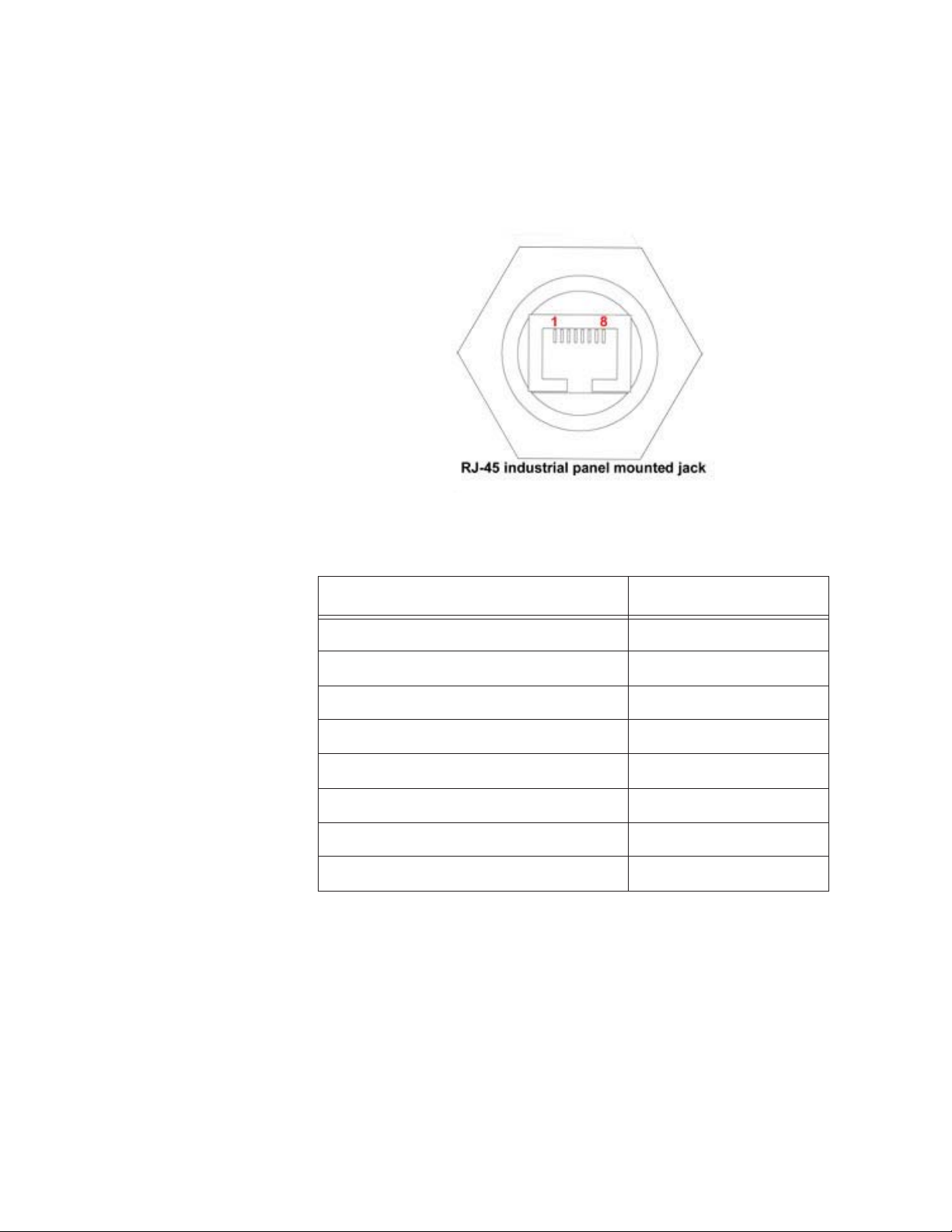
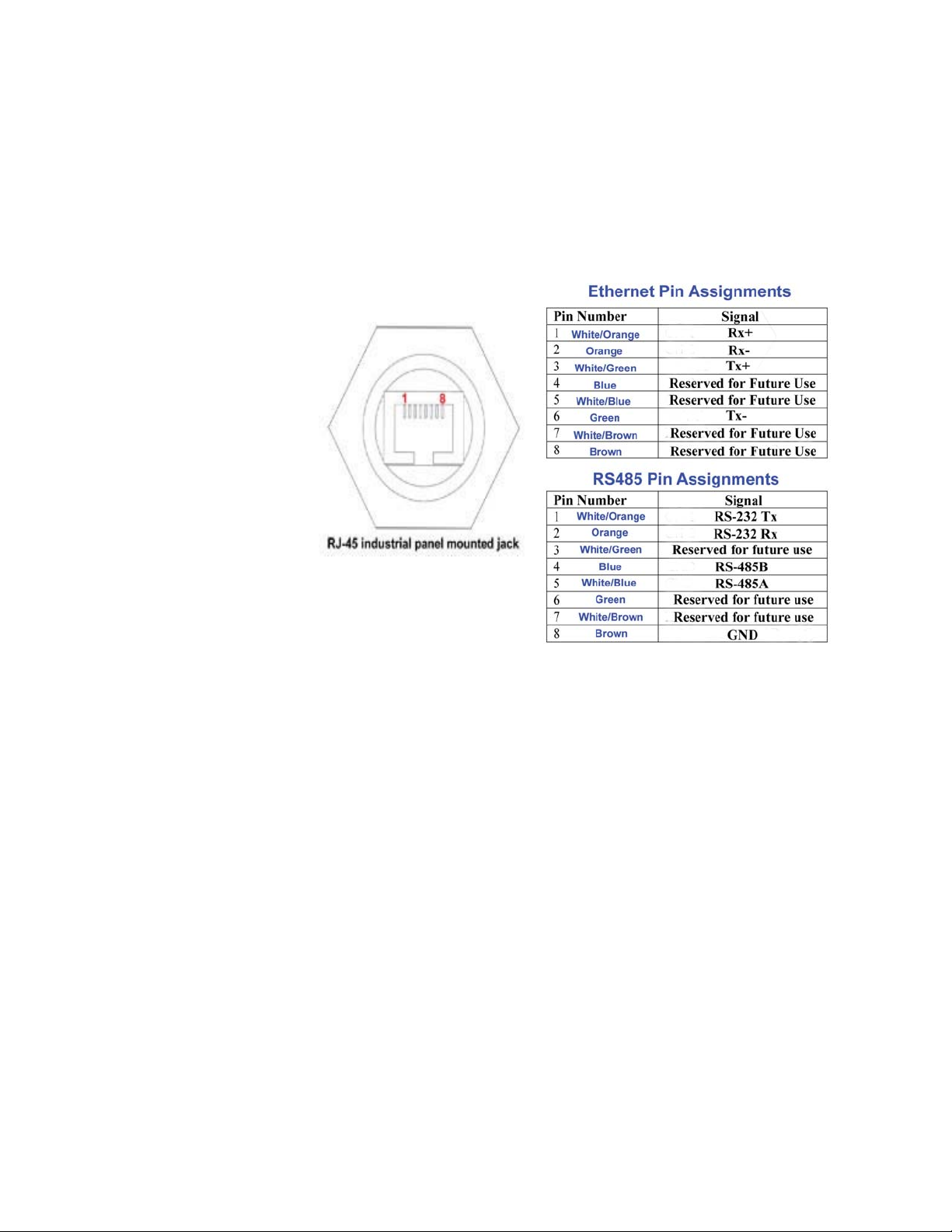
Figure 2-2 displays the REMOTE-4PN Series industrial RJ45
connector and tables 2-5 and 2-6 show pin assignments.
Figure 2-2 RJ45 Pin Assignments
Table 2-5 MODBUS RJ-45 Pinouts
RS485 RJ-45 Pin Description Signal Name
1 White/Orange RS232 Tx
2 Orange RS232 Rx
3 White/Green Reserved for Future Use
4 Blue RS485B
5 White/Blue RS485A
6 Green Reserved for Future Use
7 White/Brown Reserved for Future Use
8 Brown Ground
248083317-1 Rev 4 2-7

Lighthouse REMOTE-4PN Series Operating Manual
Table 2-6 Ethernet RJ-45 Pinouts
Ethernet RJ-45 Pin Description Signal Name
1 White/Orange Rx+
2 Orange Rx-
3 White/Green Tx+
4 Blue Reserved for Future Use
5 White/Blue Reserved for Future Use
6 Green Tx-
7 White/Brown Reserved for Future Use
8 Brown Reserved for Future Use
Please refer to the “Data Cable Build” on page 2 of “Getting Started”
(Chapter 3) for detailed instructions for terminating Cat5, Cat5e or
Cat6 cabling for use with this connector. Parts for completing this task
are available from Lighthouse if they were not provided with the order
or have been damaged and need to be replaced.
Annual Calibration
The manufacturer recommends that the Lighthouse instrument be
calibrated annually by a Certified Lighthouse Service Provider to
ensure that it continues to perform within specification.
When Calibration comes due, the Service LED will illuminate and stay ON
during sampling mode until the instrument has been calibrated.
2-8 248083317-1 Rev 4

00
3 Getting Started
Unpacking
and Initial
Inspection
Shipping
Instructions
WARNING:
If the instrument is
damaged during a
return shipment due
to inadequate user
packing, the warranty
may be voided and all
repairs required will
be at cost.
The instrument is thoroughly inspected and tested at the factory and is
ready for use upon receipt.
When received, inspect the shipping carton for damage. If the carton is
damaged, notify the carrier and save the carton for carrier inspection.
Inspect the unit for broken parts, scratches, dents, or other damage.
If the carton is not damaged, keep it for reshipment when returning the
instrument for the annual factory calibration or a Return Merchandise
Authorization for repair. Replacements are available for purchase.
Should it become necessary to return the unit to the factory for any
reason, contact Lighthouse Customer Service or visit our website,
www.golighthouse.com/rma, and obtain a Return Merchandise
Authorization (RMA) number. Reference this number on all shipping
documentation and purchase orders. After receipt of the RMA number,
follow the shipping instructions below:
1. Use the original container, nozzle caps and packing materials
whenever possible. If the instrument contains a battery, remove it
before packing the instrument. If the battery needs to be shipped,
package it separately and refer to www.golighthouse.com/rma for
detailed instructions.
2. If the original container and packing materials are not available,
wrap the unit in "bubble pack", surround with shock-absorbent
material and place in a double-wall carton - the instrument should
not rattle around when the carton is vigorously shaken. If the
instrument is damaged during shipment due to inadequate user
packing, the warranty may be voided and all repairs required will
be at cost. Contact Lighthouse to purchase a replacement shipping
container and nozzle caps.
3. Seal container or carton securely. Mark "FRAGILE" and write the
Return Merchandise Authorization (RMA) number on any
unmarked corner.
4. Return the instrument to the address provided by a Lighthouse
representative or the RMA website.
248083317-1 Rev 4 3-1

Lighthouse REMOTE-4PN Series Operating Manual
Data Cable
Build
Note: The term, "hub", is
used frequently in this
manual to indicate an
RS485 connection point hub, computer, PLC, etc.
An industrial RJ45 connector is required to attach the instrument to an
RS485 or Ethernet network (model dependant) and may be supplied in
kit form with the instrument. A replacement adapter kit is available
from Lighthouse. This section of the manual will show construction of
this special cable and connector.
Requirements
The following tools and materials are required to build / attach the
sealed industrial RJ45 connection used on the REMOTE-4PN Series.
• Solid core Category 5e Unshielded Twisted-Pair 24AWG wire
(CAT5e UTP), minimum
• CAT5e UTP plenum wire may be required for installation in ceiling
plenum area
• Industrial RJ45 kit
• Wire strippers
• RJ45 crimp tool
Site Preparation
WARNING: Both ends of the cable must be wired the same.
References are made throughout this section to the EIA/TIA-568B
standard for ethernet/RJ45 wiring that must be followed.
Failure to wire both ends to this standard will cause failure of the
instrument and may damage the instrument, the hub or both and
void the respective warranties.
When all needed tools and materials are ready, proceed through the
following steps:
1. Check with local regulatory agencies to determine installation
restrictions and cable requirements for the application before
starting cable runs.
2. Make the necessary cable "runs" and leave about two to three feet
at each end as a "service loop". When pulling CAT5, CAT5e or
CAT6 cable, prevent cable kinking and knotting or the cable may
break internally and cause failures. Typical installations use
Unshielded Twisted Pair (UTP) but Shielded Twisted Pair (STP)
may be required in areas of high electrical noise equipment, such as
3-2 248083317-1 Rev 4

Getting Started
Wire
Loom
RJ45
Lock
RJ45
Connector
Seal
CAT5e Cable
Lock
Ring
RJ45 Housing
Clamping
Nut
around generators, fans and fluorescent lights. When cable has to
be installed in the false ceilings or air space above a work area
(plenum), plenum cable may be required.
3. Even though the RJ45 connectors used to build ethernet cables are
typically the same on both ends, the connector supplied in the kit
MUST be used on the instrument end.
4. If STP wire is needed, the RJ45 required for wire termination is
metal-jacketed and provides a grounding point for the cable’s
shield. Only one end of the cable should be grounded. This
provides a shield to block electrical noise from entering the wire. If
both ends of the cable are grounded, a ground loop may be created
and cause failures of the attached equipment. Because hubs or
data-gathering devices typically use grounded connector housings,
the hub end is usually best for the ground connection. Check with
the local IT (Information Technology) personnel for specific wire
termination and installation details.
Procedure
1. Remove 1-1/2-inch to two-inches of insulation from the instrument
end of the cable, taking extreme care to not nick or cut the
individual wires. Do NOT strip the individual wires.
2. Remove the contents of the Industrial RJ45 connector from the
package - do NOT dispose of or lose any pieces. Compare the
contents with Figure 3-1. Contact Lighthouse Support if it appears
that something is missing from the package.
Figure 3-1 REMOTE-4PN Series RJ45 Cable Parts
3. Remove the large lock ring from the RJ45 Housing.
248083317-1 Rev 4 3-3

Lighthouse REMOTE-4PN Series Operating Manual
4. Loosen the RJ45 Housing Clamping Nut to allow the CAT5e cable
to pass through the housing.
5. Insert the stripped end of the cable through the large Lock Ring and
RJ45 Housing as illustrated in Figure 3-2. Make sure the ring is
oriented as shown. If it is reversed, the cable will have to be cut,
the RJ45 connector discarded and a new connector installed.
Figure 3-2 Housing with Cable Inserted
6. Separate the pairs of wires down to about 1-inch from where the
insulation starts. There will be an orange, a green, a blue and a
brown pair of wires. Each pair will have a solid color wire and a
wire striped with the color of that pair. Do not get them confused the orange and brown pair may look alike in plenum cable and
"swapping" these two pairs will cause failure of the instrument.
7. Carefully untwist each pair about 1/2-inch and straighten the wire.
The individual wires will be inserted into the Wire Loom shown in
Figure 3-1 and Figure 3-3.
Note straightened portion
Note the twisted portion
Figure 3-3 Close-up of Wire Loom
Note the shape of the Loom - inserting the wire into the larger opening
is the correct method as shown in Figure 3-3.
3-4 248083317-1 Rev 4

Getting Started
View is tab facing reader
View is from RJ45
opening
1/4-inch maximum
1/2-inch maximum
8. Separate the wires and insert them into the loom based on the EIA/
TIA-568B standard. When all of the wires are in the correct holes,
push the loom onto the wires as far as it will go and verify that at
least one-half-inch of each wire extends beyond the edge of the
loom. This will allow for trimming the wires in a straight line
parallel to the loom edge. One-quarter-inch is required for
crimping into the RJ45 connector. Review the photos in Figure 3-4
to ensure accuracy.
Note:
wires in the loom changes
at positions 4 through 6.
The "pairing" of
9. Trim the ends of the wires in a straight line to one-quarter-inch as
illustrated in the center panel of Figure 3-4.
Figure 3-4 EIA/TIA-568B Color Code Example
10. Insert the wires and loom into the RJ45 connector (lock tab facing
down) and push inward until they fully butt against the end of the
wire channels as shown in Figure 3-5. The loom helps to keep the
wires positioned so they will go into the correct channel for
crimping.
248083317-1 Rev 4 3-5
Figure 3-5 Loomed Wires Being Inserted into RJ45

Lighthouse REMOTE-4PN Series Operating Manual
Insert the RJ45 connector into a crimp tool similar to that shown in
Figure 3-6. Maintain inward pressure while crimping the wires into
their channels.
Figure 3-6 Typical RJ45 Crimp Tool
11. Check the cable wire ends in the RJ45 to make sure they have been
crimped properly. If the crimp was not successful, removing the
connector at this point is a lot easier than after everything is
installed and communications with the instrument are failing.
12. Review Figure 3-7 for an illustration of how tightly each wire end
should fit against the end of each channel. If removal of the RJ45
connector is required because of a poor crimp, contact Lighthouse
to order replacement connectors. The connectors supplied are
designed specifically for this application and using the wrong
connector may result in failure, even if the crimp operation appears
to have been successful.
Figure 3-7 Close-up - Wire Ends Butted to Channel Ends
It may be difficult to get a straight line across the ends of the wires but
gaps or differences in length of 1/8-inch between wires may cause
failures.
3-6 248083317-1 Rev 4

Getting Started
13. Squeeze the latch tab to allow it to enter the slot in the housing as
shown in Figure 3-8 and pull the cable through the connector
housing, bringing the RJ45 into the housing.
Figure 3-8 Close-up of RJ45 Latch
14. Push the RJ45 connector fully into the housing and insert the Lock
Clip, round edge out as illustrated in Figure 3-9, until it is flush.
Figure 3-9 Lock Clip Installation
15. Hand tighten the Clamping Nut until snug. See Figure 3-10.
Figure 3-10 Tighten Cable Clamp Nut
248083317-1 Rev 4 3-7
Lighthouse REMOTE-4PN Series Operating Manual
16. Install the sealing ring onto the front of the connector housing. This
seal is held in place when the connector is locked onto the
instrument. See Figure 3-11.
Figure 3-11 Install Connector Seal
17. Slide the large lock ring down the cable and over the cable housing
body. It may need a twisting action to fully position it against its
retainer ring. Verify that its larger opening is facing outward, away
from the cable. See Figure 3-12.
Figure 3-12 Cable Connector Completed
Note: It is presumed that the REMOTE-4PN Series will be used in a
network of RS485/MODBUS instruments. Therefore, references are
made to a "hub" or the "hub end" of the ethernet cable.
The "hub" may be a computer equipped with an RS232 adapter, an
RS485 hub or one of many RS485 data gathering equipment.
3-8 248083317-1 Rev 4
Getting Started
18. The hub end of the cable run can now be terminated. After both
ends are terminated, the wire should be checked using an ethernet
100baseT cable tester (not just a continuity tester) to ensure that the
signals and ground will be reliable. Steps 6 through 12 can be used
as a reference for termination of the hub end. Figure 3-13 illustrates
how the wires should be connected.
Mount the
REMOTE-4PN
Figure 3-13 RJ45 to Cat5 Pinout
19. Make sure the hub power is OFF or the hub end of the cable is
disconnected from the equipment before connecting the cable to the
instrument, but do NOT connect it, yet. Connecting cables is
discussed later in this chapter.
The REMOTE-4PN Series uses a NEMA style enclosure and mounting
to a flat vertical surface is required for proper operation. Pump flow
control is managed by the REMOTE-4PN Series pump controller.
Power to the REMOTE-4PN Series is managed by a power switch on
the NEMA enclosure bottom plate. The cover lock uses a flat blade or
coin to turn the latch to the open or closed position. Do NOT apply
power to the REMOTE-4PN Series until cables are attached properly at
both ends.
Sample tubing runs should terminate at the instrument location and
should use Bevaline tubing to prevent static and particle dropout. The
REMOTE-4PN Series instrument supports remote monitoring when
equipped with a tubing kit of 3 meters.
248083317-1 Rev 4 3-9

Lighthouse REMOTE-4PN Series Operating Manual
If the Inlet tubing is run over walls or around corners, keep the bend
radius greater than ninety degrees and three feet.
Do not patch sections together and keep the tubing supported to prevent
sagging and kinking over time.
Typical installations use a short length of tubing and a barbed ISO
probe that is either handheld or supported on a tripod.
Connecting the tubing to the instrument Inlet requires removing the cap
from the Inlet connector and installing the ferrule and nut assemblies
on the tubing as shown in Figure 3-14. This may be done with the
Outlet connector, as well, if the pump output requires that it be
exhausted to another area. The procedure is the same for the Outlet.
Connect
Interface and
Power Cables
Figure 3-14 Nut and Ferrule Installed on Tubing
After the ethernet and AC Power cables have been completed, they are
ready for connecting the REMOTE-4PN Series to AC power and datagathering equipment. Proceed as follows:
Connections
The top of the instrument has the inlet line, which supplies sample air
to the sensor. Using the compression fittings is required to allow wipedown of the instrument. See Figure 3-15.
Inlet
Figure 3-15 Instrument Top Connections
3-10 248083317-1 Rev 4

Getting Started
HEPA
RS232/RS485
Filter
Data Port
Power Switch
Outlet
fitting
Pump Remote
AC IN
Figure 3-16 shows the bottom connectors for the REMOTE-4PN
Series.
Figure 3-16 Instrument Bottom Connections
Communication Port (Data Port)
The Data Port uses either RS232/RS485 MODBUS or MODBUS TCP/
IP (for Ethernet) protocols (see Figure 3-13 on page 9 for pinout
differences). To connect the RS485 MODBUS counter to a PC requires
an adapter cable. Please contact a Lighthouse Sales Representative for
this cable.
1. Make sure that any RS485/MODBUS
cable will NOT
be connected to an Ethernet TCP/IP LAN.
Connecting to these networks may result in damage to the
instrument or the LAN and will void their respective warranties.
The Ethernet
version REMOTE-4PN can, of course, be conncted
to an Ethernet LAN.
2. For information on how to use the Data Port to change the
instrument settings, please refer to “Programming with MODBUS
Protocol” on page 5-1.
instrument’s communication
248083317-1 Rev 4 3-11

Lighthouse REMOTE-4PN Series Operating Manual
Data Cable Install
WARNING: Make
sure the data cable is
NOT attached to the hub
before it is connected to
the REMOTE-4PN.
Power to the REMOTE4PN should be OFF when
connecting to the hub.
Best practices dictate that power to equipment on both ends of the data
cable should be OFF before a cable is attached. That is not always
practical, especially if the instrument will be attached to a network with
actively-monitored devices and service cannot be interrupted.
If the REMOTE-4PN is involved in a new installation, power should be
OFF at both ends, cables installed and power applied to the REMOTE4PN then hub. If power cannot be removed from the hub end, make
sure the REMOTE-4PN is powered OFF before connecting the data
cable.
The required data cable incorporates an O-ring and provides a positive
seal through its twist-lock design. The AC Power cable incorporates
the same twist-lock action. Figures in this section illustrate how both
of these cables are "mated" to the REMOTE-4PN Series.
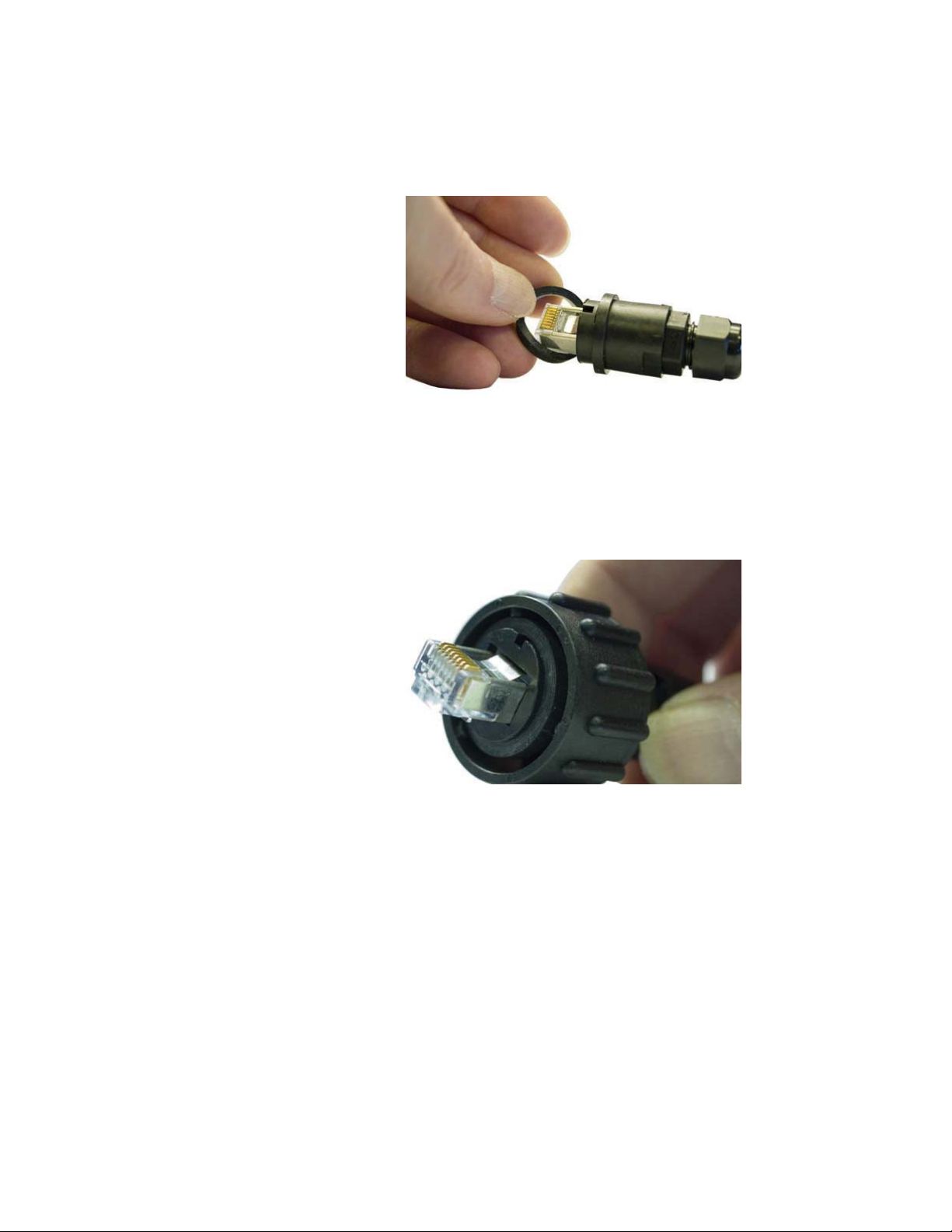
Note that Figure 3-17 shows the orientation of the key. Make sure the
cable is positioned as shown before connecting. Do NOT force the
connector or it will be damaged.
Figure 3-17 Cable Attachment Step 2
1. Insert the male cable connector into the sensor receptacle, key in
the down position. Make sure the cable fully seats into the
receptacle.
3-12 248083317-1 Rev 4

Getting Started
Twist clockwise
to lock cable
onto instrument
Lock groove
2. Figure 3-18 shows the twist motion required to lock cable into
place - make sure the lock groove and lock sleeve mate.
Figure 3-18 Cable Receptacle Lock Groove
3. Figure 3-19 shows the final "seating" of the twist lock. The free
end of the cable may now be connected to the RS485 hub, power
applied to the hub and the sensor powered up.
248083317-1 Rev 4 3-13
Figure 3-19 Cable Fully Attached

Lighthouse REMOTE-4PN Series Operating Manual
Mounting
Screws
Block
Pump Remote Cable Install
1. Figure 3-20 shows the Pump Remote cable connector. The
connector block must be removed before attaching 22-16 AWG
stranded wires.
Figure 3-20 Pump Remote Cable Connector
Note: If the remote
switch is no longer needed,
reinstall the jumper or the
pump will not run when
power is applied to the
REMOTE-4PN.
2. Loosen the two mounting screws using a small slotted screw driver.
Pull out to remove the connector block, then loosen the two screws
holding the wire jumper and replace it with 22-16 AWG twistedpair wire of sufficient length to reach the remote switch location.
3. Tighten the screws to hold the wire in place and reattach the
connector block by pushing in on the block. Make sure it is
properly positioned as it is keyed to fit only one way.
4. Tighten the two mounting screws to lock the block in place.
Energize Connections
1. Connect the signal cable to the hub or data-gathering equipment.
2. Connect the AC Power cord to the AC source.
3. Apply AC power by turning the power switch ON.
4. Power should be applied to the instrument, indicated by the
REMOTE-4PN Power LED illuminating; the pump should start
running if the jumper is in place or the Pump Remote switch is ON.
After approximately twenty seconds, data will be supplied by the
REMOTE-4PN Series to data-gathering equipment or network.
Best practices dictate that power to equipment on both ends of the data cable
should be OFF before a cable is attached. That is not always practical,
especially if a Lighthouse LMS Server or other equipment is monitoring
devices around the clock and service cannot be interrupted.
3-14 248083317-1 Rev 4

If the REMOTE-4PN is involved in a new installation, power should be OFF at
both ends, cables installed and power applied to the REMOTE-4PN then hub.
If power cannot be removed from the hub end, make sure the REMOTE-4PN
is powered OFF before
connecting the data cable.
Operation Understanding the LEDs
Getting Started
Note: The REMOTE-
4PN incorporates a pump
protection circuit that turns
the pump OFF if the Inlet
air supply is blocked. To
restore the instrument to
normal operation, clear the
obstruction, open the
cover, turn the switch OFF,
wait a few seconds and
turn the switch ON. The
pump should start.
The front-panel LEDs have specific meanings when illuminated.
Figure 3-21 shows location of the LEDs and gives a brief description of
their meaning.
Power
Flow
Sampling
Service
Figure 3-21 Front Panel LEDs
• The green POWER LED turns on when the instrument is powered
on.
• The green FLOW LED turns on when the flow is within
specification (programmed parameters) and will blink when flow is
out of specification.
• The orange SERVICE LED will turn on and remain steady if Laser
power is out of range, the sensor optics are dirty, the view volume
contains foreign objects or the Calibration has come due on the
instrument. If calibration is due, the LED illuminates during
sampling mode until the instrument has been calibrated.
• The blue SAMPLING LED indicates the Sample mode is active.
248083317-1 Rev 4 3-15

Lighthouse REMOTE-4PN Series Operating Manual
• If the internal pump stops running, the Inlet air supply may be
obstructed and the pump protection circuit has turned the pump
OFF. The FLOW LED will also blink. To restore normal pump
operation, find and clear the obstruction and open the instrument
cover. Turn the switch OFF, wait a few seconds and turn the switch
ON. The pump should start and remain running. Contact
Lighthouse Technical Support if this fails to restore normal pump
operation.
3-16 248083317-1 Rev 4

00
4 Communication Set Up
This chapter contains information on how to set up the REMOTE-4PN
in order to program and communicate with it.
Definitions of
Terms Used
This list is provided for the convenience of the user or technician.
• ARP - Address Resolution Protocol, a program that can change
the ARP Cache of a host by adding or removing IP addresses.
Each IP address is associated to a MAC address.
• ARP Cache - List of IP addresses and their associated MAC
addresses for hosts whose addresses cannot be resolved normally.
• DHCP - Dynamic Host Configuration Protocol, a program
running on a server that issues IP addresses to computers or
devices (Hosts) on its LAN.
• Gateway - a network device that controls traffic between two or
more networks.
• Hardware address - a unique identifying code programmed by the
factory into a network device, such as a network PCB, comprised
of six two-digit groups of letters A-F and numbers 0-9.
• Host - a computer or device that allows access to itself via a LAN.
• IP (Internet Protocol) Address - a unique logical address used to
identify a host on a TCP/IP network.
• LAN - Local Area Network, a group of computers or hosts
connected together in a relatively small geographical area, such
as a building or floor of a building.
• MAC address - the same as hardware address.
• Netmask - a logical hexadecimal number that prevents accessing
hosts outside of its range. A bit value of zero allows access and a
non-zero blocks access.
• Subnet - a logical grouping of hosts based on their IP addresses.
• TCP/IP - a communication protocol suite that is used for the
Internet and a large number of LANs that allows hosts to share
data.
• Telnet - a communication program used primarily to issue
commands directly to a TCP/IP-based host.
248083317-1 Rev 4 4-1

Lighthouse REMOTE-4PN Series Operating Manual
REMOTE-4PN
Communication
Modes
The default communication mode for the REMOTE-4PN series is
MODBUS TCP over Ethernet. An alternative is MODBUS ASCII
over Ethernet.
Communicating with the Instrument
The RJ-45 connector marked "Data Port" shown in Figure 4-1 is used
to connect the unit to a port of a desktop or laptop PC or to an RS485
MODBUS or Ethernet network with the appropriate cabling or adapter.
Data Port
Figure 4-1 REMOTE-4PN Series Bottom Connectors
Data Port
The Data Port RJ-45 connector provides RS485 signals. Changing the
instrument communication mode requires changing its physical
configuration. If the LWS Network Adapter will be used to attach the
REMOTE4-PN to an Ethernet network or the instrument must operate
in a mode other than RS485 MODBUS, contact Lighthouse Technical
Support for more information. Table 4-1 and Table 4-2 illustrate RJ45
pins and the signals assigned.
4-2 248083317-1 Rev 4

Communication Set Up
The pinouts are defined as follows:
Table 4-1 MODBUS RJ-45 Pinouts
RS485 RJ-45 Pin Description Signal Name
1 White/Orange RS232 Tx
2 Orange RS232 Rx
3 White/Green Reserved for Future Use
4 Blue RS485B
5 White/Blue RS485A
6 Green Reserved for Future Use
7 White/Brown Reserved for Future Use
8 Brown Ground
Table 4-2 Ethernet RJ-45 Pinouts
Ethernet RJ-45 Pin Description Signal Name
1 White/Orange Rx+
2 Orange Rx-
3 White/Green Tx+
4 Blue Reserved for Future Use
5 White/Blue Reserved for Future Use
6 Green Tx-
7 White/Brown Reserved for Future Use
8 Brown Reserved for Future Use
An RJ-45 to DB-9 modular adapter to connect the REMOTE-4PN to a
computer DB9 COM port is available from Lighthouse. The pinouts of
the RJ-45 to DB9 adapter are shown in Table 4-3.
248083317-1 Rev 4 4-3

Lighthouse REMOTE-4PN Series Operating Manual
Table 4-3 RJ-45 to DB-9 Connections
RJ-45 Pin Signal Name DB-9 Pin
1TX2
2RX3
8 Ground 5
3DTE7
RS232 Communications
WARNING: Contact
Lighthouse Technical
Support for the correct
instrument configuration
BEFORE attempting to
use RS232 COM mode.
Failure to heed this
warning can result in
damage to PC,
instrument or both.
WARNING: Contact
Lighthouse Technical
Support for the correct
instrument configuration
BEFORE attempting to
use RS485 COM mode
with a PC. Failure to
heed this warning can
result in damage to PC,
instrument or both.
RS232 is used for point-to-point communication and may be used to
program the instrument via a stand-alone PC.
To connect the instrument to a computer using RS232 Protocol:
1. Remove power from the instrument.
2. Connect the RJ45 end of the LWS RS232 Converter Cable to the
Data Port on the instrument.
3. Attach the USB connector of the RS232 Converter Cable to any
available USB Port on a computer.
4. Apply power to the instrument.
RS485 Communications
The instrument uses RS485 as its default communication mode.
To use the RS485 protocol with a computer USB port, an RS485 / USB
converter must be used. Please contact a Lighthouse Sales
Representative for an RS485 converter kit that includes the cable and
driver software needed to set this up.
4-4 248083317-1 Rev 4

Communication Set Up
Connecting to a PC
To connect the instrument to a computer using RS485 Protocol:
1. Remove power from the instrument.
2. Connect the RJ45 end of the LWS RS485 converter cable to the
REMOTE-4PN Data Port.
3. Connect the USB end of the RS485 converter to any available USB
port on the computer and wait for computer to install drivers.
4. Make sure each REMOTE-4PN has a unique non-zero address or
data will be lost then power on the instrument.
The REMOTE-4PN complies with EIA’s RS485 standards in Table 4-4.
Table 4-4 EIA Industry Standards for RS485 Communications
SPECIFICATIONS RS485
Mode of Operation Differential
Total Number of Drivers and Receivers on
One Line (One driver active at a time for
32 Drivers
32 Receivers
RS485 networks)
Maximum Cable Length 4000 ft. (1,219.2 m)
Maximum Data Rate (40 ft. - 4000 ft. for
10Mb/s - 100Kb/s
RS422/RS485)
Maximum Driver Output Voltage -7V to +12V
Driver Output Signal Level (Loaded
+/-1.5V
Min.): LOADED
Driver Output Signal Level (Loaded
+/-6V
Max.): UNLOADED
Driver Load Impedance (Ohms) 54
Max Driver Current in High Z State
+/-100μA
(POWER ON)
Max Driver Current in High Z State
+/-100μA
(POWER OFF)
Receiver Input Voltage Range -7V to +12V
Receiver Input Sensitivity +/-200mV
Receiver Input Resistance (Ohms), (1
>
12k
Standard Load for RS485)
248083317-1 Rev 4 4-5

Lighthouse REMOTE-4PN Series Operating Manual
Ethernet
Configuration
The Ethernet REMOTE-4PN comes preconfigured to use DHCP and receive an IP
address automatically. If this is not a
desired configuration, use this section to
change these settings.
If the user does not understand the terms
used or the possible impact of changing
the REMOTE-4PN’s settings, do NOT
proceed without contacting the facility’s IT
personnel.
The following procedure requires a preapproval and planning by the IT
department and a joint setup effort.
Please Note: The Ethernet version of Lighthouse Worldwide Solutions REMOTE-4PN
instrument uses MODBUS ASCII over Ethernet. Connecting a REMOTE-4PN particle
counter directly to an Ethernet network should only be done with the permission and
guidance of the network administrator.
4-6 248083317-1 Rev 4

Communication Set Up
The primary advantage of using the REMOTE-4PN on an Ethernet
network is that a separate network does not have to be installed just for
the instruments. Using the REMOTE-4PN Data Port allows the
instruments to co-exist with computers, printers and servers on a LAN
that is already in place, thereby reducing installation costs.
This document will explain how to program the instruments Ethernet
chipset through its TCP/IP interface. It will also list typical equipment
required and provide some troubleshooting information. The end of this
chapter includes examples of T568A and T568B wiring diagrams for
straight-through and cross-over cables.
Lantronix
Software Use
Use Lantronix DeviceInstaller to make configuration changes to IP
Address and subnet.
1. Start the Lantronix DeviceInstaller program. DeviceInstaller will
automatically begin searching for attached devices. The Hardware
Address (MAC Address) for the REMOTE-4PN will be displayed
as shown in Figure 4-2.
• Confirm the device by verifying that the Hardware address
displayed in DeviceInstaller matches the address on the back of the
instrument.
Ethernet Chipset
MAC Address
Figure 4-2 Detecting Attached Devices
248083317-1 Rev 4 4-7

Lighthouse REMOTE-4PN Series Operating Manual
Web Configuration Tab
Green Arrow
OK
2. Select and double-click the XPort for the REMOTE-4PN to open
the Device Details tab.
• Select the Web Configuration tab and then press the green arrow.
The Windows Security Login window will open.
• Select OK without entering a username or password. See
Figure 4-3.
Figure 4-3 Web Configuration Tab
3. The Device Server Configuration Manager will open as shown in
Figure 4-4.
Figure 4-4 Device Server Configuration Manager
4-8 248083317-1 Rev 4

Communication Set Up
4. Select Network Settings and choose the Use the following IP
configuration: radio button.
• Enter the IP Address: “XXX.XX.X.XX” and the Subnet Mask:
“255.255.255.0”.
• Leave the Default Gateway: blank unless the IT department
indicates one is needed. If a gateway is needed, the IT department
will provide one.
• Press the OK button to save the settings. Network Settings will
display Done! See Figure 4-5.
Figure 4-5 Network Settings
Note: These settings
should be the default
settings and may not need
to be changed.
5. Select Serial Settings under Channel 1.Verify that the Port
Settings are set to the following:
• Protocol: RS485 - 2 wire
• Flow Control: None
• BaudRate: 19200
• Data Bits: 8
248083317-1 Rev 4 4-9

Lighthouse REMOTE-4PN Series Operating Manual
• Parity: None
• Stop Bits: 1.
• Press the OK button to save the settings. Serial Settings will display
Done! See Figure 4-6.
Figure 4-6 Serial Settings
6. As shown in Figure 4-7, select Connections and verify that
Connect Protocol and Connection settings are set to the following:
• Protocol: Modbus
• Local Port: 502
• Accept Incoming: Yes.
• Under Modbus Mode, set the Message Timeout to “1000ms” if
not already set.
• Press the OK button. Connections Settings will display Done! as
4-10 248083317-1 Rev 4

shown in Figure 4-7.
Communication Set Up
Search Icon
Figure 4-7 Connection Settings
7. Select Apply Settings link to save the setting to the REMOTE-4PN
as shown in Figure 4-8.
Apply Settings
Figure 4-8 Apply Settings
248083317-1 Rev 4 4-11

Lighthouse REMOTE-4PN Series Operating Manual
8. Select the Search icon to refresh the attached devices and verify
that the IP Address for the REMOTE-4PN has been changed.
Preparing for
Network
Installation
Note:
network where these
instruments will operate
must have an available IP
address for each
instrument. The IP
scheme, or subnet, must
match that of the PC that
will be used to retrieve the
data from the instruments.
Contact Lighthouse
Technical Support at 800945-5905 (USA Toll Free)
or 541-770-5905 (Outside
of USA) for additional
information.
Note:
screen shots are examples
only. Use only the values
provided by the Network
Administrator.
The production
All values in
Equipment Required:
• Network enabled Personal Computer (IBM-compatible)
• REMOTE-4PN
• Small 5-port hub or switch and two 3-foot long straight-through
Cat5 Ethernet cables (For connection to network)
• Or one 3-foot cross-over Cat5 Ethernet cable (For connection to a
PC)
Software Required:
Contact the network administrator if any of the following are not
installed or not functional:
• Windows 2000, XP Professional, or Windows 7
• Telnet
Additional Requirements:
1. Contact the network administrator and obtain administrator rights
on the PC to be used for this procedure.
2. For each unit to be attached, obtain an unused static IP address,
Gateway IP address and the appropriate Netmask for the LAN
into which they will be installed.
3. Create a list and record the MAC address(es) for all REMOTE-
4PNs to be configured. It is suggested that the IP address that will
be used for each REMOTE-4PN be written next to its MAC
address. This list can be provided to the network administrator for
future reference.
4. The PC being used to program the REMOTE-4PN must be using
the same subnet that the adapter will use. See the network
administrator for assistance with this.
5. The PC that will monitor or retrieve data from the instrument(s)
must be using the same subnet and gateway programmed on the
REMOTE-4PN(s) network interface.
Configure
Ethernet REMOTE-4PN Configuration
Device
This section is organized based on the cable used to perform the
4-12 248083317-1 Rev 4

Communication Set Up
Ethernet REMOTE-4PN programming.
Straight-through Cat5 or Cat6 cables require a hub or switch and two
straight-through cables.
Using a cross-over Cat5/Cat6 cable connects the PC directly to the
REMOTE-4PN with no hub.
Each of these configuration modes will be explained separately. If
troubleshooting is required, the cross-over cable technique is easier to
use in the field because it requires fewer devices.
It cannot be stressed enough, however, that the instrument and PC be
configured using the same IP scheme (IP range, Default Gateway and
Netmask).
For troubleshooting outside of the LAN, it is suggested that the PC’s IP
address be used as the Default Gateway for both the PC and the
REMOTE-4PN.
Note:
are examples only. Data
displayed and command
responses may differ.
Screens shown
Frequently, it is necessary to change the REMOTE-4PN Ethernet
parameters to allow for easier troubleshooting. When this is needed,
make sure the instrument is reprogrammed to its previous network
settings before reattaching to the LAN. Contact Lighthouse Technical
Support at 800-945-5905 (USA Toll Free) or 541-770-5905 (Outside of
USA) or the network administrator for additional information.
Straight-through Cat5/Cat6 Setup:
This section requires the PC, two straight-through Cat5 cables and the
hub or switch.
1. Connect one end of a straight-through Cat5 cable to the Ethernet
REMOTE-4PN’s Data Port.
2. The other end of the cable should plug into one port on the hub or
switch.
3. Attach another straight-through cable to the PC’s RJ45 receptacle
and an open port on the hub or switch.
4. Proceed to “Windows Telnet Programming:” on page 4-14.
248083317-1 Rev 4 4-13

Lighthouse REMOTE-4PN Series Operating Manual
Cross-over Cat5/Cat6 Setup:
1. Attach one end of the cross-over cable to the RJ45 receptacle on
the PC.
2. Attach the other end of the cable to the REMOTE-4PN Data Port.
3. Apply power to the REMOTE-4PN. Apply power to the PC if it is
not already running. Observe the LEDs on the PC’s RJ45
connector - blinking indicates network/instrument activity.
Program the
Interface
WARNING:
only the steps or
commands as provided
in this guide. Failure to
heed this warning can
result in damage to
equipment, personal
injury or data loss and
may void the equipment
warranties.
Perform
Windows Telnet Programming:
This section is included just in case some of the automated programs
are not working and programming the instrument is not, yet, successful.
1. Start Windows.
2. On the Taskbar, click on Start.
3. Select Run as shown in Figure 4-9.
Figure 4-9 RUN Screen
4. In the Run window, type CMD and click OK. See Figure 4-10.
Note: Typing commands
in the command console
requires a space between
the instruction and the
command variables. For
example, arp is followed by
a space, then -d and
another space then the *.
Figure 4-10 Starting the Command Console
4-14 248083317-1 Rev 4

Communication Set Up
5. A command prompt window will open. Clear the ARP Cache by
typing arp -d * at the command line and press Enter. Ignore any
error messages that indicate the address table doesn’t exist or has
no entries. See Figure 4-11.
Figure 4-11 Clear Address Table Command
6. The next step requires the unit’s assigned IP and its MAC
address. The MAC address is a group of six two-digit characters
(0-9 and A-F) found on the back of the REMOTE-4PN that may
be referred to as the HW address.
7. The next step adds the IP and MAC addresses to the ARP Cache
which allows direct communications with the instrument before
an IP is programmed into its Ethernet interface.
8. Type arp –s xxx.xxx.xxx.xxx nn-nn-nn-nn-nn-nn and press Enter.
Replace the x’s with the desired IP address, such as 192.168.0.10
or 10.10.0.15, and the n’s with the desired MAC address, such as
00-20-4a-8a-26-31. The IP address will be four segments total
with up to 3 digits per segment, each segment separated by a
period. Note that the MAC address segments are separated by
dashes (-), not periods. See Figure 4-12.
Figure 4-12 ARP Command to Add New IP
9. Activate the REMOTE-4PN Ethernet interface by typing, telnet
xx.xx.xx.xx 1 (replace x’s with the IP address to be used for the
instrument) and press Enter. This command will cause a connect
error but is required to establish communications. See
Figure 4-13.
Figure 4-13 Telnet 1
248083317-1 Rev 4 4-15

Lighthouse REMOTE-4PN Series Operating Manual
10. Type telnet xx.xx.xx.xx 9999 and press Enter. This command
accesses the telnet port of the instrument. The expected error
message from Step 9. is shown in Figure 4-14.
The user will have 4 seconds to respond in the next step. If the user
responds too slowly, they will have to repeat step 10.
11. Press Enter to start the REMOTE-4PN Ethernet interface setup
program. Figure 4-15 displays some of the default settings - make
no changes to these settings except as instructed.
Figure 4-14 Telnet 9999
Figure 4-15 Starting the Set Up Program
12. Type 1 to set the IP address. Type the desired IP address and press
Enter. See Figure 4-16.
4-16 248083317-1 Rev 4

Communication Set Up
Figure 4-16 Assigning IP Address
13. Type Y to set the Gateway IP address. Type the Gateway IP
address and press Enter. See Figure 4-17.
Figure 4-17 Assigning Gateway IP Address
14. Type Y to set the Netmask. type the desired Netmask value and
press Enter. See Figure 4-18.
Figure 4-18 Assigning Netmask
248083317-1 Rev 4 4-17

Lighthouse REMOTE-4PN Series Operating Manual
15. Type N in response to “Change telnet config password” as shown
in Figure 4-19. The instrument is shipped without a password.
Changing the telnet password or providing one is discouraged,
except for absolute security requirements. If a password is
applied and forgotten, the instrument will have to be returned to
Lighthouse to get the password cleared.
Figure 4-19 Telnet Config Password Screen
Note:
Ethernet restarts, it will
lose connection to the PC,
reported as, “Connection
to host lost”.
When the
16. Type S to Save and restart and press Enter to save the changes.
See Figure 4-20.
Figure 4-20 Saving the Settings
17. Perform Step 7. though Step 16. for each REMOTE-4PN.
4-18 248083317-1 Rev 4

Communication Set Up
WARNING: Step 18 is
very important to prevent
network address errors
on the PC when the
process is complete.
TIA568A and
TIA568B wire
Examples
18. Clear the ARP Cache by type arp –d * and press Enter. If this is
not done before quitting this process, the PC may create “ghost
IPs” on the LAN and cause serious problems with the network.
19. Type Exit to quit the command console.
The TIA568A and TIA568B standards are used for creating Ethernet
cables. Either standard can be used to create a straight through cable
but both ends must be wired the same (TIA568A to TIA568A or
TIA568B to TIA568B).
Even though the TIA568A is considered the desired wiring standard for
either Cat5, Cat5e or Cat6, most cables built today are built using the
TIA568B standard. To avoid confusion or possible miswiring errors, it
advised to use whichever standard is the defacto standard used in the
facility.
Figure 4-21 TIA568A, TIA568B Comparison
Connect
REMOTE-4PN
to Ethernet
LAN
248083317-1 Rev 4 4-19
Connect Ethernet Cable to Instrument
Power OFF the Ethernet REMOTE-4PN before connecting the
instrument to a network then attach the network cable to the REMOTE4PN and the other end to the network receptacle. Apply power to the
instrument and check the port LEDs to make sure the connection is
working.
When all steps are completed, the REMOTE-4PN will supply data to
the LAN connection. After approximately 60 seconds, monitoring
equipment and software should “see” the instrument and be able to
retrieve data from it.
Contact Lighthouse Worldwide Solutions Technical Support at 800945-5905 (USA Toll Free) or 541-770-5905 (Outside of USA) for
additional information or further assistance.

Lighthouse REMOTE-4PN Series Operating Manual
4-20 248083317-1 Rev 4

00
5 Programming with
MODBUS Protocol
The REMOTE-4PN can be programmed using the MODBUS Protocol.
The full protocol is detailed in Appendix B: “MODBUS Register Map
v1.44” on page B-1.
This chapter contains the information needed to program the basic
configuration for the instrument using the MODBUS protocol.
DIP Switches During power-up and reset, the counter reads its DIP switches to
determine its operating mode. The REMOTE-4PN is shipped
configured to use the MODBUS protocol.
Protocol
Settings
WARNING: ALWAYS
use the RS485 to RS232
adapter combination
whenever connecting the
REMOTE-4PN to a PC
COM port. Failure to do
so will damage the
instrument, PC COM port
or both.
Power On/
Auto Start
The MODBUS Protocol is used through an RS232 or RS485 interface
with all necessary adapters and the following COM port settings:
• Baud Rate: 19200
•Data Bits: 8
• Stop Bits: 1
• Parity: None
• Flow Control: None
When powering up the instrument, it will begin sampling using the
default configuration:
• Location = 0
• Sample Time = 60 seconds
• Hold Time = 0 seconds
248083317-1 Rev 4 5-1

Lighthouse REMOTE-4PN Series Operating Manual
Note: The automatic
starting of the sampling
accommodates systems
that do not send a START
command but just polls the
instrument for its data.
Running the
Instrument
Using
MODBUS
To stop the sampling, send the command 10 or 12 to command register
40002.
Stopping the sampling will set the Device Status bit in Register 40003
to 0.
The applicable action commands are shown here in Table 5-1
Table 5-1 Action Commands
Value Actio n
1 Saves all writable 4xxxx register values to the EEPROM.
3 Clears the Data Buffer. Record count is set to zero.
4 Saves the instrument parameters in the 40xxx registers to
the EEPROM. Parameters include Sample Time, Hold
Time, and Location.
7 Start Pump (flow regulated by internal setpoint).
8 Stop Pump.
9 Manual Start.
The instrument samples continuously until it receives a
Manual Stop command. Ignores local timing parameters.
Sets Sample Time for data record to equal the time
interval between the Manual Start and Manual Stop
command. Should be preceded by Start Pump command.
10 Manual Stop.
Stops sampling. Records counts since Manual Start.
Should be followed by Pump Stop command.
11 Instrument Start (Automatic Counting).
Uses defined Hold Time and Sample Time. Instrument
starts pump, executes samples and holds until an
Instrument Stop command is issued.
12 Instrument Stop.
Aborts current sample. Stops pump and data collection.
Each of the described action commands above are written to the
command register (40002).
AUTOMATIC Counting Mode
In Automatic counting mode, the instrument uses the configured
sample time and hold time to record samples.
5-2 248083317-1 Rev 4

Programming with MODBUS Protocol
The instrument will continue running samples at the configured sample
time until it receives a stop command. When the stop command is
given, the most current data will not record to the buffer.
After setting all the instrument parameters as described in “Changing
the Default Instrument Parameters” on page 5-5, write these commands
to the Command register (40002):
11 Start Instrument; to start pump and recording
12 Stop Instrument; to stop pump and recording
MANUAL Counting Mode
In Manual counting mode, the computer starts the sample and the
instrument continues counting until a stop command is given. At that
point, the sample time is listed at whatever the time interval was
between the start command and the stop command.
Write these commands to the Command register (40002):
7 Start Pump - must be sent before ’9’, below
8 Stop Pump - must be sent after ’10’ below
9 Start Instrument; to start recording (does not start pump - see ’7’).
10 Stop Instrument; to stop recording after desired sample time (does
not stop pump - see ’8’).
248083317-1 Rev 4 5-3

Lighthouse REMOTE-4PN Series Operating Manual
Configuring
with the
MODBUS
Protocol
Register Data Type Description
Setting the Real Time Clock
The Real Time Clock (RTC) can be read in registers 40027 and 40028
as shown in Table 5-2.
Register 40027 is the high word for the real time clock; 40028 is the
low word. The date/time is calculated as the number of seconds since
midnight of 1/1/1970.
The date & time is stored in a 4-byte unsigned integer or as a 32-bit
unsigned integer.:
Table 5-2 Real Time Clock Registers
40027 unsigned integer Real Time Clock (RTC) [high]. Works in
conjunction with 40028. Displays date and
time, in number of seconds since
midnight, 1/1/1970.
40028 unsigned integer Real Time Clock [low]
In order to change the RTC to the current local date/time, enter the high
and low values as unsigned integers to registers 40035 and 40036
respectively, the Data Set registers.See Table 5-3.
Table 5-3 Data Set Registers
Register Data Type Description
40035 unsigned integer Data Set [high]. Works in conjunction
with 40036. Data entered here is applied
to the device through the command
register.
40036 unsigned integer Data Set [low]
Then write the command 13 to the command register 40002. This will
write the values in the Data Set registers (40035 and 40036) to the RTC
registers (40027 and 40028).
5-4 248083317-1 Rev 4

Programming with MODBUS Protocol
Changing the Default Instrument Parameters
The main instrument parameters involved with the operation of the
REMOTE counter are Location, Sample Time, and Hold Time. See
Table 5-4.
The Location is set by writing an unsigned integer to register 40026.
The range of values is from 0 to 999.
Sample Time and Hold Time both use 2 registers, a high word and a
low word. If the desired value for any of these parameters is less than
or equal to 9 hours, 6 minutes and 7 seconds (32767 seconds), then
only the low word register needs to be written with the value in
seconds.
The low word register for Sample Time is 40034.
The low word register for Hold Time is 40032.
Table 5-4 Instrument Parameters
Register Data Type Description
40026 unsigned integer Location number
Specifies location of Particle Counter.
40031 unsigned integer Hold Time [high].
Works in conjunction with 40032. Number of
seconds to wait between sample periods. Max value
is 359,999, which equals 99h 59m 59s
40032 unsigned integer Hold Time [low]
40033 unsigned integer Sample Time [high].
Works in conjunction with 40034. Number of
seconds to sample. Max value is 86,399, which
equals 23h 59m 59s.
40034 unsigned integer Sample Time [low]
Using Sensor Setting Registers
Certain configuration settings can be sent to the counter through these
registers.
Sensor Setting Registers 40001 and 40003 through 40023 are protected
and should not be changed.
248083317-1 Rev 4 5-5

Lighthouse REMOTE-4PN Series Operating Manual
Location (Register 40026)
For Particle Counters, this value specifies at what location a sample
was recorded.
For Manifold Controllers, this value specifies the manifold position.
Writing a value from 1-32 to this register will move the manifold arm
to that position on the manifold. Value 0 moves the arm to the Home
position.
Hold Time (Registers 40031, 40032)
The Hold Time is used for pausing in between samples for multiple
cycles. If Hold Time is greater than 1 minute, the pump will turn off.
This time is specified in seconds. The maximum value is 359,999
seconds (high word: 5, low word: 32319) which is 99 hours, 59
minutes, and 59 seconds. To set the Hold Time to a value less than 9
hours, 6 minutes, 7 seconds, enter the number of seconds in the low
register (40032).
WARNING:
set the Sample Time
value to less than 30
seconds.
Do NOT
During Hold Time, the Device Status bit is 0 (Idle).
Sample Time (Registers 40033, 40034)
The Sample Time specifies the time period of each sample, specified in
seconds. The maximum value is 86,399 seconds (high word: 1, low
word: 20863) which is 23 hours, 59 minutes, 59 seconds. The
instrument is programmed at the factory with a default value of 60
seconds. Do NOT set this value to less than 30 seconds.
To set the Sample Time to a value less than 9 hours, 6 minutes, 7
seconds, enter the number of seconds in the low register (40034).
During the Sample Time, the Device Status is 1 (Sampling).
5-6 248083317-1 Rev 4

00
A Limited Warranty
Limitation Of Warranties:
A. Lighthouse Worldwide Solutions (LWS) warrants that all
equipment shall be free from defects in material and
workmanship under normal use for a period of two years from
date of shipment to Buyer except that LWS does not warrant that
operation of the software will be completely uninterrupted or
error free or that all program errors will be corrected. Buyer shall
be responsible for determining that the equipment is suitable for
Buyer’s use and that such use complies with any applicable
local, state, or federal law. Provided that Buyer notifies LWS in
writing of any claimed defect in the equipment immediately
upon discovery and any such equipment is returned to the
original shipping point, transportation charges prepaid, within
two years from date of shipment to Buyer and upon examination
LWS determines to its satisfaction that such equipment is
defective in material or workmanship, i.e. contains a defect
arising out of the manufacture of the equipment and not a defect
caused by other circumstances, including, but not limited to
accident, misuse, unforeseeable use, neglect, alteration,
improper installation, improper adjustment, improper repair, or
improper testing, LWS shall, at its option, repair or replace the
equipment, shipment to Buyer prepaid. LWS shall have
reasonable time to make such repairs or to replace such
equipment. Any repair or replacement of equipment shall not
extend the period of warranty. If the Instrument is modified or in
any way altered without the explicit written consent of LWS then
the warranty is null and void. This warranty is limited to a period
of two years, except as noted below, without regard to whether
any claimed defects were discoverable or latent on the date of
shipment. The length of warranty for pumps in hand held particle
counters is one (1) year. Batteries and accessories with all
products are warranted for one (1) year. Fuses and purge filters
carry no warranty. If a third party battery is used in the product,
the product warranty is null and void. If the battery is charged by
a third party battery charger the battery warranty is null and void.
B. If Buyer shall fail to pay when due any portion of the purchase
price or any other payment required from Buyer to LWS under
this contract or otherwise, all warranties and remedies granted
under this Section may, at LWS’s option, be terminated.
C. THE FOREGOING WARRANTY IS EXCLUSIVE AND IN
LIEU OF ALL OTHER REPRESENTATIONS, WARRANTIES
AND COVENANTS, EXPRESS OR IMPLIED WITH
RESPECT TO THE EQUIPMENT AND ANY DEFECTS
THEREIN OF ANY NATURE WHATEVER, INCLUDING
AND WITHOUT LIMITATION WARRANTIES OF
MERCHANTABILITY OR FITNESS FOR A PARTICULAR
PURPOSE. LWS SHALL NOT BE LIABLE FOR, AND
BUYER ASSUMES ALL RISK OF, ANY ADVICE OR
FAILURE TO PROVIDE ADVICE BY LWS TO BUYER
REGARDING THE EQUIPMENT OR BUYERS USE OF THE
SAME. UNDER NO CIRCUMSTANCES SHALL LWS BE
LIABLE TO BUYER UNDER ANY TORT, NEGLIGENCE,
STRICT LIABILITY, OR PRODUCT LIABILITY CLAIM
AND BUYER AGREES TO WAIVE SUCH CLAIMS. LWS’s
SOLE AND EXCLUSIVE LIABILITY AND BUYERS SOLE
AND EXCLUSIVE REMEDY, FOR ANY
NONCONFORMITY OR DEFECT IN THE PRODUCTS OR
ANYTHING DONE IN CONNECTION WITH THIS
CONTRACT, IN TORT, (INCLUDING NEGLIGENCE),
CONTRACT, OR OTHERWISE, SHALL BE AS SET FORTH
IN THE SUBSECTION A HEREOF AS LIMITED BY
SUBSECTION B HEREOF. THIS EXCLUSIVE REMEDY
SHALL NOT HAVE FAILED OF ITS ESSENTIAL PURPOSE
(AS THAT TERM IS USED IN THE UNIFORM
COMMERCIAL CODE) PROVIDED THAT THE SELLER
REMAINS WILLING TO REPAIR OR REPLACE
DEFECTIVE EQUIPMENT (AS DEFINED IN SUBSECTION
A) WITH A COMMERCIALLY REASONABLE TIME
AFTER RECEIVING SUCH EQUIPMENT. BUYER
SPECIFICALLY ACKNOWLEDGES THAT SELLER’S
PRICE FOR THE EQUIPMENT IS BASED UPON THE
LIMITATIONS OF LWS’S LIABILITY AS SET FORTH IN
THIS CONTRACT.
Warranty Of Repairs After
Initial Two (2) Year Warranty:
A. Upon expiration of the initial two-year warranty, all parts and
repairs completed by an authorized Lighthouse repair technician
are subject to a six (6) month warranty.
B. Other than the above, LWS makes no warranty of any kind,
expressed or implied, except that the products manufactured and
sold by LWS shall be free from defects in materials and
workmanship and shall conform to LWS’s specifications; Buyer
assumes all risk and liability resulting from use of the products
whether used singly or in combination with other products. If
instrument is modified or in any way altered without the explicit
written consent of LWS, then the warranty is null and void.
C. WARRANTY REPAIRS SHALL BE COMPLETED AT THE
FACTORY, BY AN AUTHORIZED SERVICE LOCATION,
BY AN AUTHORIZED SERVICE TECHNICIAN, OR ON
SITE AT BUYER’S FACILITY BY A LIGHTHOUSE
AUTHORIZED EMPLOYEE. BUYER PAYS FREIGHT TO
FACTORY; SELLER WILL PAY STANDARD RETURN
FREIGHT DURING THE WARRANTY PERIOD. BUYER
MAY SELECT A FASTER METHOD OF SHIPMENT AT ITS
OWN EXPENSE.
248083317-1 Rev 4 A-1

Lighthouse REMOTE-4PN Series Operating Manual
A-2 248083317-1 Rev 4

00
B MODBUS Register
Map v1.44
COMM
Settings
Supported
MODBUS
Commands
Lighthouse particle counters using MODBUS require the following
communications settings:
Table B-1 MODBUS Communications Settings
Baud Rate 19200
Data Bits 8
Stop Bits 1
Parity None
Hardware Protocol RS232C or RS485 standard
Software Protocol MODBUS ASCII (supports upper/lower case)
The MODBUS slave address is set on the particle counter.
Table B-2 MODBUS Registers
Hex Command Description
03 Read Holding Registers
04 Read Input Registers
06 Write Single Holding Register
See www.modbus.org for documentation on how to use these
commands.
248083317-1 Rev 4 B-1

Lighthouse REMOTE-4PN Series Operating Manual
Register Map Sensor Settings Registers
Instrument settings are stored in holding registers (the 4xxxx series),
which are mostly read/writable. Not all holding registers are writable.
Table B-3 describes the content of these registers.
Table B-3 Sensor Settings Registers
Register Data Type Description
40001 unsigned integer MODBUS register map version. Matches the version number
of this document. Major version digits are hundreds. Minor
version digits are tens and ones. For example, v1.35 = 135d =
0087h
40002 unsigned integer Command register. Makes the counter execute a command.
See the description of this register in the table below.
40003 unsigned integer Device Status.
[bit 0=RUNNING, bit 1=SAMPLING, bit 2=NEW DATA]
40004 unsigned integer Firmware version. Major version digits are hundreds. Minor
version digits are tens and ones. For example, 210 = V2.10
40005 unsigned integer Serial Number [high]
40006 unsigned integer Serial Number [low]
40007 ASCII string Product Name char[0], char [1] (NULL terminated string)
40008 ASCII string Product Name char[2], char [3]
40009 ASCII string Product Name char[4], char [5]
40010 ASCII string Product Name char[6], char [7]
40011 ASCII string Product Name char[8], char [9]
40012 ASCII string Product Name char[10], char [11]
40013 ASCII string Product Name char[12], char [13]
40014 ASCII string Product Name char[14], char [15]
40015 ASCII string Model Name char[0], char [1] (NULL terminated string)
40016 ASCII string Model Name char[2], char [3]
40017 ASCII string Model Name char[4], char [5]
40018 ASCII string Model Name char[6], char [7]
40019 ASCII string Model Name char[8], char [9]
B-2 248083317-1 Rev 4

MODBUS Register Map v1.44
Table B-3 Sensor Settings Registers
Register Data Type Description
40020 ASCII string Model Name char[10], char [11]
40021 ASCII string Model Name char[12], char [13]
40022 ASCII string Model Name char[14], char [15]
40023 unsigned integer Flow Rate. Divide by 100 to get rate in CFM. For example,
100 = 1CFM
40024 signed integer Record Count. Total number of records stored in the counter
40025 signed integer Record Index. Zero based index to data in 3xxxx register
series. Must be lower than the record count (register 40024).
Set this index to expose a counter’s record in the 3xxxx
registers. Set to -1 to retrieve last record stored in the counter.
40026 unsigned integer Location number
Particle Counters
Manifold Controller
: Specifies location of Particle Counter.
: Specifies Manifold position. Setting this
value moves to that position on the manifold.
40027 unsigned integer Real Time Clock (RTC) [high]. Works in conjunction with
40028. Displays date and time, in number of seconds since
midnight, 1/1/1970.
40028 unsigned integer Real Time Clock [low]
40029 unsigned integer Initial Delay [high]. Works in conjunction with 40030.
Number of seconds to wait before starting the first sample. Max
value is 359,999, which equals 99h 59m 59s.
40030 unsigned integer Initial Delay [low]
40031 unsigned integer Hold Time [high]. Works in conjunction with 40032. Number
of seconds to wait between sample periods. Max value is
359,999, which equals 99h 59m 59s
40032 unsigned integer Hold Time [low]
40033 unsigned integer Sample Time [high]. Works in conjunction with 40034.
Number of seconds to sample. Max value is 86,399, which
equals 23h 59m 59s.
40034 unsigned integer Sample Time [low]
40035 unsigned integer Data Set [high]. Works in conjunction with 40036. Data entered
here is applied to the device through the command register.
40036 unsigned integer Data Set [low]
248083317-1 Rev 4 B-3

Lighthouse REMOTE-4PN Series Operating Manual
Table B-3 Sensor Settings Registers
Register Data Type Description
40037 unsigned integer Relay Mode or Alarm Mode - Relay mode only
change or instrument will malfunction!
- Do NOT
40038 unsigned integer Relay Parameter - Control parameter for given relay mode
40039 unsigned integer Laser Reference Voltage (millivolts)
40040 unsigned integer View Volume. Divide by 100 to obtain percentage.
For example: 6500d = 65.00%
40041 ASCII String Flow Unit. Defines unit the flow rate value is based on.
char [0], char [1] (NULL terminated string)
40042 ASCII String Flow Unit. char [2], char [3]
40043 unsigned integer Calibration Reference Voltage (millivolts)
40047 signed integer Calibration Due Date [high] - Indicates when instrument is due
for calibration
40048 signed integer Calibration Due Date [low]
Device Status
The Device Status register (40003) displays the current status of the
device.
Table B-4 Device Status
Bit Description
0 RUNNING: Set when a start command is executed
remotely via Command 9 (manual start) or Command 11
(instrument start) or through the user interface. The flag
will remained set until a stop command is executed.
1 SAMPLING: This is set only when the instrument is
actually sampling data that is to be recorded. Caution
must be used in sending a command during this time that
may invalidate current sample.
2 NEW DATA: Set to 1 to indicate that a new data record
has been recorded and it hasn't been read via modbus yet.
When a data record has been read via modbus (registers
30001 to 30999), then this flag is reset to zero.
B-4 248083317-1 Rev 4

MODBUS Register Map v1.44
Command
Register
The Command Register (40002) is used to make the device perform an
action. The register performs an action when an integer value is written
to it. The action is completed when the device sends a MODBUS
response. When this register is read, it always returns a zero.
Table B-5 Command Register
Value Action
1 Saves all writable 4xxxx register values to the EEPROM.
2 Reserved for future use.
3 Clears the Data Buffer. Record count is set to zero.
4 Saves the instrument parameters in the 40xxx registers to the
EEPROM. Parameters include Sample Time, Hold Time, Initial
Delay, and Location.
5 Enable Remote Control. Locks out the instrument’s user interface.
Can only change instrument parameters via MODBUS.
6 Enable Local Control. Unlocks the instrument’s user interface.
Instrument changes can be made at the device itself or through
MODBUS.
7 Start local pump, if applicable - perform before 9 below.
8 Stop pump, if applicable - perform after 10 below.
9 Manual Start.
The instrument samples continuously until it receives a Manual
Stop command. Ignores local timing parameters. Sets Sample Time
for data record to equal the time interval between the Manual Start
and Manual Stop command. If applicable to device, does not start
pump.
10 Manual Stop.
Stops sampling. Records counts since Manual Start.
11 Instrument Start (Automatic Counting).
Particle Counters
Interval and counting mode. Instrument executes samples and holds
until an Instrument Stop command is issued. For instruments with
pumps, this command will start the pump.
Manifold Controller
counting and changing position when Instrument Stop command is
issued.
: Uses defined Initial Delay, Hold Time, Sample
: Uses defined Manifold Sequence. Stops
12 Instrument Stop. Aborts current sample. Stops pump, if applicable.
Stops data collection.
248083317-1 Rev 4 B-5

Lighthouse REMOTE-4PN Series Operating Manual
Table B-5 Command Register
Value Action
13 Set Real Time Clock.
Writes "Data Set" values (from Registers 40035 & 40036) to the
local Real Time Clock. New time value is saved.
Data
Registers
Data is stored in the input registers (30xxx series), which are read-only.
All data items are four bytes long and are stored across two registers.
Byte and word order is big-endian. Thus, data items are formed by
placing the high bytes in front of the low bytes.
Example:
<High Bytes><Low bytes> = <4 Byte Data Item>
Not all particle and analog channels are active. Retrieving data from an
inactive channel returns garbage. See the Data Enable Registers
section of this document for details on how to record data from active
channels.
This entire series of registers represents one data record in the device.
The Record Index Register (40025) must be changed to index other
records here.
The first record in the data buffer is located at Index=0. The most
recently saved value is at Index=-1.
Table B-6 Data Registers
Register Data Type Description
30001 signed integer Timestamp [high] (# of seconds
since midnight, 1/1/1970)
30002 signed integer Timestamp [low]
30003 unsigned integer Sample Time [high] (In seconds)
30004 unsigned integer Sample Time [low]
30005 signed integer Location [high] (Place where data
was recorded)
30006 signed integer Location [low]
30007 unsigned integer Device Status [high]
30008 unsigned integer Device Status [low]
B-6 248083317-1 Rev 4

MODBUS Register Map v1.44
Table B-6 Data Registers
Register Data Type Description
30009 unsigned integer Particle Channel 1 [high]
30010 unsigned integer Particle Channel 1 [low]
30011 unsigned integer Particle Channel 2 [high]
30012 unsigned integer Particle Channel 2 [low]
30013 unsigned integer Particle Channel 3 [high]
30014 unsigned integer Particle Channel 3 [low]
30015 unsigned integer Particle Channel 4 [high]
30016 unsigned integer Particle Channel 4 [low]
30017 unsigned integer Particle Channel 5 [high]
30018 unsigned integer Particle Channel 5 [low]
30019 unsigned integer Particle Channel 6 [high]
30020 unsigned integer Particle Channel 6 [low]
30021 unsigned integer Particle Channel 7 [high]
30022 unsigned integer Particle Channel 7 [low]
30023 unsigned integer Particle Channel 8 [high]
30024 unsigned integer Particle Channel 8 [low]
30041 IEEE Float Analog Channel 1 [high]
30042 IEEE Float Analog Channel 1 [low]
30043 IEEE Float Analog Channel 2 [high]
30044 IEEE Float Analog Channel 2 [low]
30045 IEEE Float Analog Channel 3 [high]
30046 IEEE Float Analog Channel 3 [low]
30047 IEEE Float Analog Channel 4 [high]
30048 IEEE Float Analog Channel 4 [low]
30065 IEEE Float Background Voltage [low] -
percentage based on Calibration
Reference value
30066 IEEE Float Background Voltage [high]
248083317-1 Rev 4 B-7

Lighthouse REMOTE-4PN Series Operating Manual
Register Data Type Description
30067 IEEE Float Flow Value [low] - 0.0 if flow is
30068 IEEE Float Flow Value [high]
30069 IEEE Float Laser Voltage [low] - percentage
30070 IEEE Float Laser Voltage [high]
Table B-6 Data Registers
below reference, 1.0 if flow is at
reference, 1.1 if flow is above
reference
based on Laser Reference Voltage
Note: Particle data is a
cumulative raw count
regardless of the
instrument’s settings.
Note: Although
MODBUS sends 4 bytes of
status information,
Lighthouse instruments
only use the first (least
significant) byte.
The timestamp field indicates when the data record was recorded.
Timestamps are stored as the number of seconds since 1/1/1970, the
Unix time epoch. This value can be written directly into a C/C++
time_t data type to be used by ANSI C time functions.
Device Status Word
The registers used for the Device Status Word are 30007 and 30008.
The bit order of the Device Status Word is 7 to 0 (right to left), where
bit 7 is the most significant bit and bit 0 is the least significant bit.
The bits within the Device Status Word are flagged to indicate
particular conditions of the currently indexed data record.
If multiple states occur, the bits are added together. For example, a
Flow Alert and a Particle Overflow would return a value of 6 in register
30008 (bits 1 and 2 are set TRUE).
Table B-7 Device Status Word
Bit Description
0 Laser Alert Status
0 = Laser is good 1 = Laser Alert
1 Flow Alert Status
0 = Flow Rate is good 1 = Flow Rate Alert
2 Particle Overflow Status
0 = No overflow 1 = Overflow occurred
B-8 248083317-1 Rev 4

Table B-7 Device Status Word
Bit Description
3 Instrument Service Status
0 = Working correctly 1 = Instrument malfunction detected.
4 Particle Threshold Exceeded Status
0 = Threshold not exceeded 1 = Threshold exceeded
Data Enable Registers
MODBUS Register Map v1.44
Note: All data records
have the same enable
states. The user does not
have to read the enable
registers for every record.
Note: All data records
have the same data types
assigned to them. The user
does not have to read the
data type registers for
every record.
The 31xxx register series is used to determine which data items in
30xxx are enabled. Enabled items contain recorded data. Data
retrieved from disabled items return garbage. Data items are disabled
for particle and analog channels not supported by the device or when
the device software is configured not to record data for those items.
The Enable Registers (31xxx series) run in parallel with the Data
Registers (30xxx series). For example, Data Register 30010’s Enable
Register is 31010. Data Register 30016’s Enable Register is 31016.
The 31xxx register states are:
00000000h = Disabled
FFFFFFFFh = Enabled
Data Type Registers
The 32xxx register series is used to identify the type of data in the
30xxx series. The Data Type registers run in parallel with the Data
Registers. For example, Data Register 30041’s Data Type register is
32041.
Data Types are assigned 4 ASCII characters across 2 registers. If a
Data Type string contains less than 4 characters, then the rest of the
string is padded with NULL characters. Note that a Data Type using all
four characters will not end with a NULL character.
Table B-8 Data Types
String Description
TIME Timestamp
STIM Sample Time
SVOL Sample Volume
248083317-1 Rev 4 B-9

Lighthouse REMOTE-4PN Series Operating Manual
Table B-8 Data Types
String Description
LOC Location
STAT Status
TEMP Temperature
RH Relative Humidity
AIRV Air Velocity
DPRS Differential Pressure
ESD Electrostatic Discharge
FLOW Flow Rate
LASV Laser Voltage
VOLT Voltage
Note: Only Particle data
types have numbers in
their strings.
PRES Pressure
Particle data items are typed specially. They contain numbers,
sometimes a space and sometimes a period used as a decimal point.
These entries are used to identify particle channel sizes and are always
expressed in microns. These types represent raw counts only.
Table B-9 Examples of Particle Data Items
String Description
0.3 Particle type of size 0.3 micron
1.0 Particle type of size 1.0 micron
20.0 Particle type of size 20.0 micron
.015 Particle type of size 0.015 micron or 15 nanometer
Data Units Registers
The 33xxx register series identifies the units used by data items in the
30xxx series. The Units Registers run in parallel with the Data
Registers. For example, Data Register 30010’s Units Register is
33010.
B-10 248083317-1 Rev 4

MODBUS Register Map v1.44
Note: Not all data types
have units. LWS Particle
Counters may use units
not listed in the table.
Units are stored as 4 character ASCII strings across 2 registers. If the
Units string contains less than 4 characters or no characters at all, the
rest of the string is padded with NULLs. Note that a Units string using
all 4 characters does not end with a NULL.
Table B-10 shows units that may be sent by the device. Some of these
units are not currently used but are reserved for future use.
Table B-10 Data Units
Units Description Units Description
# Count (For Particles) ft/m Feet per minute
% Percent m/s Meters per second
s Seconds "H2O Inches of water
min Minutes "Hg Inches of mercury
hour Hours mmWa Millimeters of water
F Fahrenheit mmHg Millimeters of mercury
C Celsius cmHg Centimeters of mercury
K Kelvin Pa Pascals
ft Feet kPa Kilopascals
m Meters Bar Bar
ft^2 Square feet mBar Milli-bar
m^2 Square meters V Volts
ft^3 Cubic feet mV Milli-volts
m^3 Cubic meters A Amperes
L Liters mA Milli-amps
CFM Cubic feet per minute Ohm Ohms
CMM Cubic meters per minute mOhm Milli-ohm
L/m Liters per minute
p/f3 Particles per cubic foot
p/m3 Particles per cubic meter
248083317-1 Rev 4 B-11

Lighthouse REMOTE-4PN Series Operating Manual
B-12 248083317-1 Rev 4

00
Index
Numerics
5-port hub 4-12
A
Accessories 2-2
Administrator rights 4-12
ARP 4-1
ARP Cache 4-1
arp -d * 4-15
arp –d * 4-19
arp –s 4-15
AUTOMATIC Counting Mode 5-2
Automatic Mode 5-2
C
Cabling Sensor 3-12
Calibration 2-3, 2-4, 2-5, 2-6
Caution
LWS Network Adapter 4-2
Channel Threshold 2-3, 2-4, 2-5, 2-6
Clear LAT 4-19
Clear the Data Buffer 5-2
Clearing the ARP Cache 4-19
CMD 4-14
Collection Optics 2-2
Command Console 4-14
Command Register B-5
Communicating with the Instrument 4-2
Communication Modes 2-3, 2-4, 2-5, 2-6, 4-2
Communication Ports 3-11
Communications 4-1
Communications Settings B-1
Connecting to a PC 4-5
Connection to host lost 4-18
Connections 3-10
Counting Efficiency 2-3, 2-4, 2-5, 2-6
Cross-over Cat5 4-12
Cross-over Cat5 Setup 4-14
D
Data Enable Registers B-9
Data loss 4-5
Data Port pinouts 4-3
Data Registers B-6
Device Status Word B-8
Data Storage
REMOTE 3014PN 2-3
REMOTE 3104PN 2-4
REMOTE 5014PN 2-5
REMOTE 5104PN 2-6
Data Type Registers B-9
Data Units Registers B-10
Default Communication Mode 4-2, 4-4
Default Instrument Parameters
Changing 5-5
Definitions 4-1
Description, general 2-1
Device Status B-4
Device Status Word B-8
DHCP 4-1
Dimensions 2-3, 2-4, 2-5, 2-6
E
Ethernet Cable
Plenum Cable 3-3
RJ45 connector 3-3
Shielded Twisted Pair (STP) 3-2
Unshielded Twisted Pair (UTP) 3-2
Ethernet Configuration 4-6, 4-12
Ethernet network 4-2
248083317-1 Rev 4 I-1

Lighthouse REMOTE-4PN Series Operating Manual
F
FLOW LED 3-15
Flow Rate 2-3, 2-4, 2-5, 2-6
G
Gateway 4-1
Gateway IP 4-12
General Info 5-1
H
Hardware address 4-1
Hold Time 5-6
Host 4-1
I
Initial Inspection 3-1
Inlet Obstruction 3-16
Internal Pump
stops running 3-16
Internal pump stops 3-16
Introduction
Description, general 2-1
Overview 2-1
IP 4-15
IP Address 4-1
IP address 4-12
IP configuration 4-9
Location 5-6
LWS Network Adapter caution 4-2
M
MAC Address 4-7
MAC address 4-1, 4-12, 4-15
MODBUS
Auto Start 5-1
Instrument Stop 5-2
Manual Start 5-2
Manual Stop 5-2
Power On 5-1
Protocol Settings 5-1
MODBUS Instrument Start 5-2
MODBUS Protocol 5-1
Power On 5-1
N
Netmask 4-1
Network address 4-5
Network administrator 4-12
Non-zero address 4-5
O
Operating Temp/RH 2-3, 2-4, 2-5, 2-6
Operation 3-15
Overview 2-1
P
L
Particle Detection 2-2
LAN 4-1
LAN-connect Warning 1-2
Lantronix Software 4-7
Lantronix Web Configuration 4-8
Laser Diode 2-2
Laser Source 2-3, 2-4, 2-5, 2-6
LED
POWER 3-15
SERVICE 3-15
Local Area Network 4-1
I-2 248083317-1 Rev 4
Personal Computer 4-12
Plenum Cable 3-3
Power 2-3, 2-4, 2-5, 2-6
Power On, Auto Start 5-1
Programming with MODBUS Protocol 5-1
R
Real Time Clock
Setting 5-4

Index
Register Map B-2
Remote Monitoring 2-2, 3-9
RS-232 Communications 4-4
RS-232/485 IN Port 4-2
RS485 4-4
RS-485 Communications 4-4
RS485 converter 4-4
Running the Instrument Using MODBUS 5-2
S
Safety 1-1
Electrostatic safety information 1-2
Laser safety information 1-1
Sample Time 5-6
SAMPLING LED 3-15
Save 5-2
Sensor Settings Registers B-2
Location 5-6
Sample Time 5-6
Using Sensor Setting Registers 5-5
Set adapter’s IP address 4-16
Setting the Real Time Clock 5-4
Shielded Twisted Pair (STP) cable 3-2
Shipping instructions 3-1
Size Ranges 2-3, 2-4, 2-5, 2-6
Specifications 2-3, 2-4, 2-5, 2-6
Start command 5-2, 5-3
Start Pump 5-2
Stop command 5-2, 5-3
Stop Pump 5-2
Storage Temp/RH 2-3, 2-4, 2-5, 2-6
Straight-through Cat5 4-12
Straight-through Cat5 Setup 4-13
Subnet 4-1
Subnet Mask 4-9
Supported MODBUS Commands B-1
U
Understanding the LEDs 3-15
Unique non-zero address 4-5
Unpacking 3-1
Unshielded Twisted Pair (UTP) 3-2
Use of Lantronix Software 4-7
V
Vacuum 2-3, 2-4, 2-5, 2-6
W
Warning
Electrostatic Discharge 1-2
Infrared Radiation 1-1
LAN-connect 1-2
Relay Mode setting B-4
Weight 2-3, 2-4, 2-5, 2-6
Z
Zero Count Level 2-3, 2-4, 2-5, 2-6
T
TCP/IP 4-1
Telnet 4-1
Telnet Programming 4-14
Tubing Kit for Remote Monitoring 2-2, 3-9
248083317-1 Rev 4 I-3

Lighthouse REMOTE-4PN Series Operating Manual
I-4 248083317-1 Rev 4

00

 Loading...