

Lighthouse REMOTE 2, REMOTE 3102, REMOTE 2012, REMOTE 3012, REMOTE 5102 Operating Instructions Manual
...

00

Lighthouse Worldwide Solutions
REMOTE 2012, 3012, 5012, 3102, 5102 Airborne Particle Counter
Operating Manual

Copyright © 2004-2008 by Lighthouse Worldwide Solutions. All rights reserved. No part of this
document may be reproduced by any means except as permitted in writing by Lighthouse
Worldwide Solutions.
The information contained herein constitutes valuable trade secrets of Lighthouse Worldwide
Solutions. You are not permitted to disclose or allow to be disclosed such information except as
permitted in writing by Lighthouse Worldwide Solutions.
The information contained herein is subject to change without notice. Lighthouse Worldwide
Solutions is not responsible for any damages arising out of your use of the LMS program.
REMOTE 2012, 3012, 5012, 3102, 5102™ are trademarks of Lighthouse Worldwide Solutions.
Microsoft®, Microsoft Windows©, and Excel© are trademarks of Microsoft Corporation.
LWS Part Number 248083201-1 Rev 6

EU DECLARATION OF CONFORMITY
Manufacturer’s Name Lighthouse Worldwide Solutions, Inc.
Manufacturer’s Address: Lighthouse Worldwide Solutions, Inc.
1221 Disk Drive
Medford, OR 97501
Declares that the product:
Product Name: Remote Airborne Particle Counter
Model Number(s): REMOTE 2012, 3012, 5012, 3102, 5102
Conforms to the following Product Specifications:
SAFETY
LASER SAFETY
EMC
UL 61010A-1 – UL Standard for Safety Electrical Equipment for Laboratory Use; Part 1: General Requirements.
Replaces UL 3101-1
Supplementary information: The product herewith complies with the requirements of the Low Voltage
Directive 73/23/EEC amended by Directive 93/68/EEC and the EMC Directive 89/336/EEC amended by Directive
93/68/EEC, and carries the CE marking accordingly.
EN61010-1:2001 Safety Requirements for Electrical Equipment for
Measurement, Control, and Laboratory Use Part I:
General Requirements IEC 61010-1:2000
CAN/CSA C22.2 Safety Requirements for Electrical
No. 1010.1-1992 Equipment for Measurement, Control, and Laboratory
Use, Part1: General Requirements
IEC 60825-1 Am. 2 Guidance on Laser Products: Conforms to
IEC 60601-2-22 FDA 21 CFR Chapter 1 Subchapter J
(Laser Notice 50)
EN61326 Electrical Equipment for Measurement, Control and
Laboratory Use EMC Requirements Part 1: General
Requirements Includes Amendment A1:1998;IEC
61326:1997 + A1:1998
Fremont, CA, May 15, 2007 William L. Shade – V.P. Engineering


00
Table of Contents
About This Manual
Text Conventions ................................................................................................................ i
Additional Help ................................................................................................................... i
Chapter 1 General Safety
Safety Considerations .................................................................................................... 1-1
Laser Safety Information ............................................................................................... 1-1
Electrostatic Safety Information .................................................................................... 1-2
Chapter 2 Introduction
Overview ........................................................................................................................ 2-1
Description ..................................................................................................................... 2-1
Accessories .................................................................................................................... 2-2
REMOTE Specifications ............................................................................................... 2-3
Chapter 3 Getting Started
Unpacking and Initial Inspection ................................................................................... 3-1
Shipping Instructions ..................................................................................................... 3-1
Interpreting the Indicators .................................................................................. 3-2
Connections ................................................................................................................... 3-3
Installation ..................................................................................................................... 3-4
Installing an Isokinetic Probe ........................................................................................ 3-5
Data Port ........................................................................................................................ 3-5
Applications ................................................................................................................... 3-7
Chapter 4 Programming
General ........................................................................................................................... 4-1
DIP Switches .................................................................................................................. 4-1
DIP Switch Settings ....................................................................................................... 4-2
GENERAL DEFINITIONS ............................................................................... 4-2
Time:Range ........................................................................................................ 4-2
248083201-1 Rev 6 t-i

Lighthouse REMOTE 2012, 3012, 5012, 3102, 5102 Operating Manual
DIP Switch Settings and Meanings ................................................................... 4-3
Procedure to Set DIP Switches .......................................................................... 4-3
Example Startup Echo, Reading DIP Switches: .................................... 4-3
Connecting the Instrument to a Terminal ...................................................................... 4-4
Power Up ....................................................................................................................... 4-6
Session Example ............................................................................................................ 4-6
ASCII Programming Syntax .......................................................................................... 4-7
Command Structure ........................................................................................... 4-7
Handshake .......................................................................................................... 4-8
Protocol .............................................................................................................. 4-8
Command Set ..................................................................................................... 4-9
VERBOSE MODE ................................................................................ 4-9
GET CURRENT SETTINGS ................................................................ 4-9
DISPLAY MENU OF COMMANDS ................................................... 4-9
START/STOP COUNTING MODE ................................................... 4-10
START Counting ..................................................................... 4-10
STOP Counting ........................................................................ 4-10
GET CURRENT VERSION NUMBER .............................................. 4-11
SET CHANNEL RANGES ................................................................. 4-11
SET SAMPLE TIME (seconds) .......................................................... 4-12
SET ALARM CHANNEL ................................................................... 4-12
SET ALARM THRESHOLD .............................................................. 4-12
Hyperterminal Alarm Alert without Alarm Suppression: .................... 4-13
SET ALARM SUPPRESSION ............................................................ 4-13
Hyperterminal Alarm Alert with Alarm Suppression: ......................... 4-13
Service High and Service Low .................................................................................... 4-14
Hyperterminal Service Alert Example: ................................................ 4-14
Service Menu ............................................................................................................... 4-15
DON’T SHOW 1 SEC DATA ............................................................. 4-15
SHOW 1 SEC DATA .......................................................................... 4-15
GET BACKGROUND LIGHT VALUE ............................................. 4-16
Chapter 5 Technical Data
Introduction .................................................................................................................... 5-1
Control Design ............................................................................................................... 5-1
START .............................................................................................................. 5-1
SETUP .............................................................................................................. 5-1
Startup Example: .................................................................................... 5-2
COUNT .............................................................................................................. 5-2
TIMER ............................................................................................................... 5-2
OUTPUT ............................................................................................................ 5-3
ALARM ............................................................................................................. 5-3
SERVICE ALERT ............................................................................................. 5-3
EXTERNAL ALARM ....................................................................................... 5-3
t-ii 248083201-1 Rev 6

Chapter 6 Maintenance Procedures
Introduction .................................................................................................................... 6-1
Safety ............................................................................................................................. 6-1
Calibration ..................................................................................................................... 6-1
Purge Count Test ........................................................................................................... 6-1
Fault Isolation ................................................................................................................ 6-2
Appendix A Limited Warranty
Limitation Of Warranties: ............................................................................................. A-1
Warranty Of Repairs After Initial Two (2) Year Warranty: ......................................... A-1
Index
Table of Contents
248083201-1 Rev 6 t-iii

Lighthouse REMOTE 2012, 3012, 5012, 3102, 5102 Operating Manual
t-iv 248083201-1 Rev 6

00
About This Manual
This manual describes the detailed operation and use of the Lighthouse
REMOTE 2 Series Airborne Particle Counters.
Text
Conventions
Note: A note appears in
the sidebar to give extra
information regarding a
feature or suggestion
WARNING: A
warning appears in a
paragraph like this and
warns that doing
something incorrectly
could result in personal
injury, damage to the
instrument or loss and/or
improper storage of data.
The following typefaces have the following meanings:
italics Represents information not to be typed
or interpreted literally. For example, file
represents a file name. Manual titles are
also displayed in italics.
boldface Introduces or emphasizes a term.
Courier font Indicates command syntax or text
displayed by the diagnostic terminal.
Bold Courier Indicates commands and information that
you type. You can use uppercase or
lowercase letters; in this manual,
commands are shown in uppercase.
Helvetica Italics Indicates a comment on a command or
text output.
Additional
Help
For more information about Lighthouse REMOTE 2 Series Airborne
Particle Counters, contact Lighthouse Worldwide Solutions.
(800) 945-5905 Sales & Support
(510) 438-0500 Outside of USA
www.golighthouse.com
techsupport@golighthouse.com
248083201-1 Rev 6 i

Lighthouse REMOTE 2012, 3012, 5012, 3102, 5102 Operating Manual
ii 248083201-1 Rev 6

00
1 General Safety
Safety
Considerations
Laser Safety
Information
Warnings and cautions are used throughout this manual. Familiarize
yourself with the meaning of a warning before operating the particle
counter. All warnings will appear in the left margin of the page next to
the subject or step to which it applies. Take extreme care when doing
any procedures preceded by or containing a warning.
There are several classifications of Warnings defined as follows:
• Laser - pertaining to exposure to visible or invisible laser radiation
• Electrostatic - pertaining to electrostatic discharge
This product contains a laser-based sensor that is a Class 1 product (as
defined by 21 CFR, Subchapter J of the Health and Safety Act of 1968)
when used under normal operation and maintenance. Service
procedures on the sensor can result in exposure to invisible radiation.
Service should be performed only by factory-authorized personnel.
The particle counter has been evaluated and tested in accordance with
EN 610109-1:1993, "Safety Requirements For Electrical Equipment
for Measurement, Control, and Laboratory Use" and IEC 825-1:1993,
"Safety of Laser Products".
WARNING: The use
of controls, adjustments
or performance of
procedures other than
those specified within
this manual may result in
exposure to invisible
(infrared) radiation that
can quickly cause
blindness.
248083201-1 Rev 6 1-1
Figure 1-1 Warning label on unit
For further technical assistance, contact our Technical Support Team at
(800) 945-5905.

Lighthouse REMOTE 2012, 3012, 5012, 3102, 5102 Operating Manual
Electrostatic
Safety
Information
WARNING: Using a
wrist-strap without an
isolation resistor will
increase the severity of
an electrical shock.
Electrostatic discharge (ESD) can damage or destroy electronic
components. Therefore, all service or maintenance work should be
done at a static-safe work station. A static-safe work station can be
created by doing the following:
• Use a grounded conductive table mat and resistor-isolated wriststrap combination
• Earth-ground all test instruments to prevent a buildup of static
charge
1-2 248083201-1 Rev 6

00
2 Introduction
Overview This operating manual introduces you to the Lighthouse REMOTE
2012, 3012, 5012, 3102, 5102 (REMOTE 2 Series) family of twochannel Airborne Particle Counters. Also included in this manual are
instructions for inspecting, using, and maintaining the instrument. Any
changes of instrument operation due to design changes are covered at
the back of this manual.
Description The 2012 instrument is manufactured to count particles at 0.2 and 0.3
micron, the 3012 counts particles at 0.3 and 0.5 micron and the 5012
model counts particles at 0.5 and 5.0 microns at 0.1 CFM. The 3102
model counts at 0.3 and 0.5 micron and the 5102 model counts particles
at 0.5 and 5.0 microns at 1.0 CFM.
The instruments are effective in both ultra-clean areas (such as Class 1
or Class 10) and in more traditional cleanzones rated as Class 100 or
higher. Refer to Specifications in this manual for additional instrument
information.
Figure 2-1 REMOTE 3012 Airborne Particle Counter
248083201-1 Rev 6 2-1

Lighthouse REMOTE 2012, 3012, 5012, 3102, 5102 Operating Manual
The particle counter uses laser diode light source and collection optics
for particle detection. The collection optics collect and focus light
scattered by the particles onto a photo diode that converts the bursts of
light into electrical pulses. The pulse height is a measure of particle
size. Pulses are counted and their amplitude is measured for particle
sizing.
The REMOTE 2 Series line of Airborne Particle counters was created
for continuous operation 24 hours per day, 7 days per week.
Using an external vacuum source, the instrument provides versatile
mounting options and can be installed where space is at a premium.
The REMOTE 2 Series instrument integrates seamlessly with large
facility monitoring/management systems and transfers 2 channels of
simultaneous particle count data using 4-20mA output.
Accessories You can order several accessories to tailor the instrument to your
needs. These accessories are listed below.
• Isokinetic Sampling Probe 0.1 or 1.0 CFM
• Sample Tubing
• Instrument to PC Cabling, RJ-45 to DB-9
• 0.1Pm Purge Filter Assembly 0.1 or 1.0 CFM Flow Rate with
Tubing
• Vacuum tubing per foot
• Cable per foot
2-2 248083201-1 Rev 6

REMOTE
Specifications
Introduction
Size Ranges, 2012 0.2 - 2.0
Size Ranges, 3012/3102 0.3 - 10.0Pm
Size Ranges, 5012/5102 0.5 - 10.0μm
Channel Thresholds, 2012 0.2, 0.3μm
Ch. Thresholds, 3012/3102 0.3, 0.5μm
Ch. Thresholds, 5012/5102 0.5, 5.0μm
Flow Rate, 2012/3012/5012 0.1 CFM (2.83 LPM)
Flow Rate, 3102/5102 1.0 CFM (28.3 LPM)
Counting Efficiency 50% (per JIS)
Laser Source Laser Diode
Zero Count Level <1 count/5 minutes (per JIS)
Vacuum Requirements External Vacuum >18" (45.7 cm) of Hg
Calibration NIST Traceable
Communication Modes 4-20mA: Ch1, Ch2
Alarms Ch1, Ch2 Count Overflow Alarm
Alerts Service Alert
Enclosure Stainless steel
Power Instrument Power: +6V to +30VDC
Loop Power: +15V to +30VDC
Dimensions 1.7" (L) x 4.2" (W) x 2.5" (H) [4.3 x 10.7 x.
6.3 cm]
Wei ght 12.5 oz (0.35 kg)
Operating Temp/RH 50° F to 104° F (10° C to 40° C) / 20% to 95%
non-condensing
Storage Temp/RH 14° F to 122° F (-10° C to 50° C) / Up to 98%
non-condensing
Table 2-1 Specifications
The manufacturer recommends that your Lighthouse instrument be
calibrated annually by a Certified Lighthouse Service Provider to
ensure that it continues to perform within specification.
248083201-1 Rev 6 2-3

Lighthouse REMOTE 2012, 3012, 5012, 3102, 5102 Operating Manual
2-4 248083201-1 Rev 6

00
3 Getting Started
Unpacking
and Initial
Inspection
Shipping
Instructions
The instrument is thoroughly inspected and tested at the factory and is
ready for use upon receipt.
When received, inspect the shipping carton for damage. If the carton is
damaged, notify the carrier and save the carton for carrier inspection.
Inspect the unit for broken parts, scratches, dents, or other damage.
Verify the contents of the package against the packing list.
If the carton is not damaged, keep it for reshipment when you return the
instrument for the annual factory calibration.
Should it become necessary to return the unit to the factory for any
reason, be sure to contact Customer Service and obtain a Return
Merchandise Authorization (RMA) number. Reference this number on
all shipping documentation and purchase orders. After receipt of the
return number, follow the shipping instructions provided below:
1. Use the original container or carton and packing materials
whenever possible.
2. If the original container and packing materials are not available,
wrap the unit in "bubble pack" plastic; surround with shockabsorbent material and place in a double-wall carton.
3. Seal container or carton securely. Mark "FRAGILE" and enter
Return Merchandise Authorization (RMA) number in any
unmarked corner.
4. Return to the address instructed by your Lighthouse representative.
248083201-1 Rev 6 3-1
Lighthouse REMOTE 2012, 3012, 5012, 3102, 5102 Operating Manual
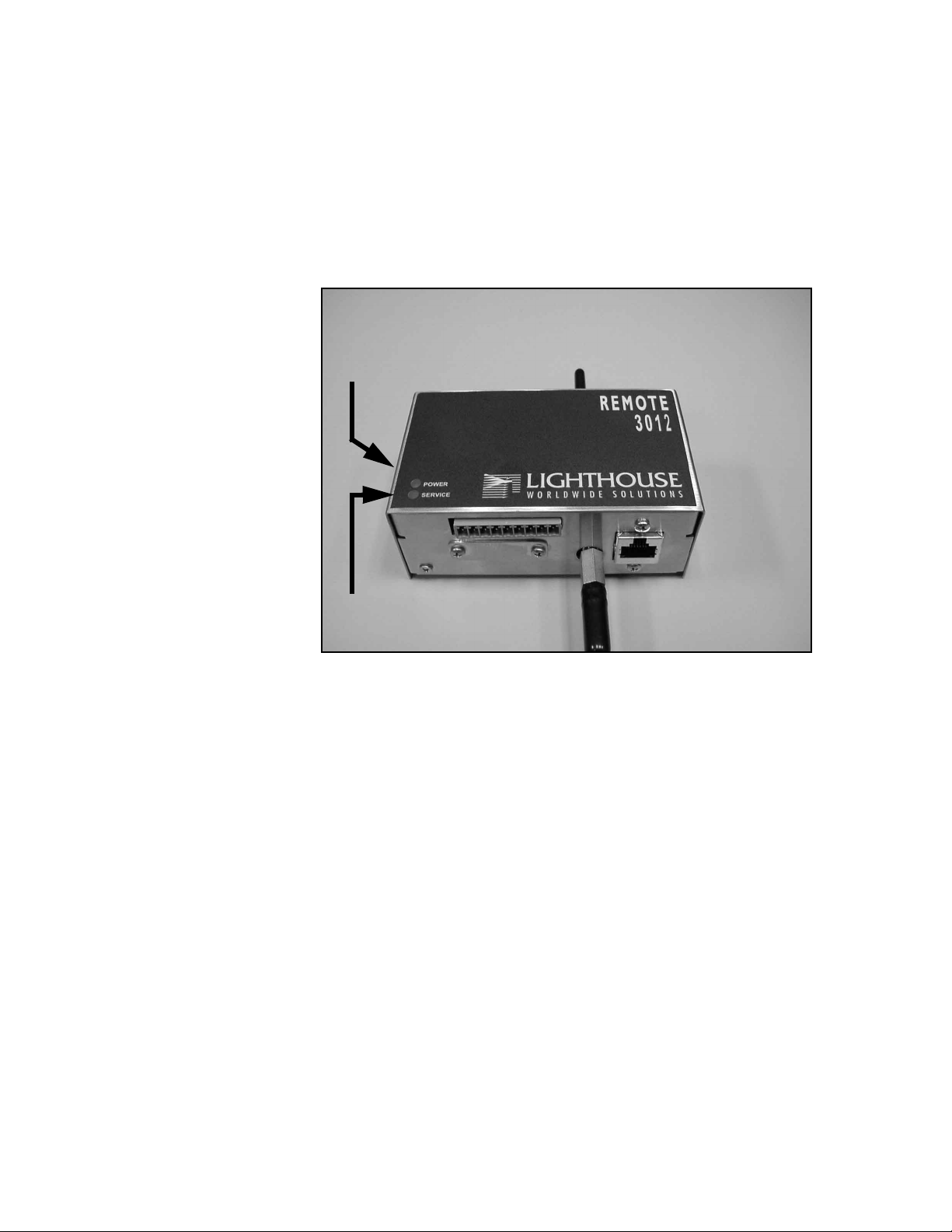
Operation Interpreting the Indicators
Both front-panel indicators have a specific meaning when illuminated.
The figure below shows location of the indicators and gives a brief
description of their meaning.
POWER LIGHT (GREEN)
SERVICE LIGHT (RED)
Figure 3-1 Front Panel LEDs
• The green POWER indicator lights when power is received through
the DATA connector.
• The red SERVICE indicator blinks if either of the Channels
overflows its programmed threshold.
• The red SERVICE indicator is ON if Laser power is low, sensor
optics are dirty or the view volume contains foreign objects.
3-2 248083201-1 Rev 6

Connections
Inlet fitting
Figure 3-2 Connections on Top of Instrument
for external
vacuum
Getting Started
Programming
Port
Figure 3-3 Connections on Bottom Right of Instrument
Figure 3-4 J10 Labeling (with Status feature on pin 5)
248083201-1 Rev 6 3-3

Lighthouse REMOTE 2012, 3012, 5012, 3102, 5102 Operating Manual
Figure 3-5 J10 Labeling (without Status feature on pin 5)
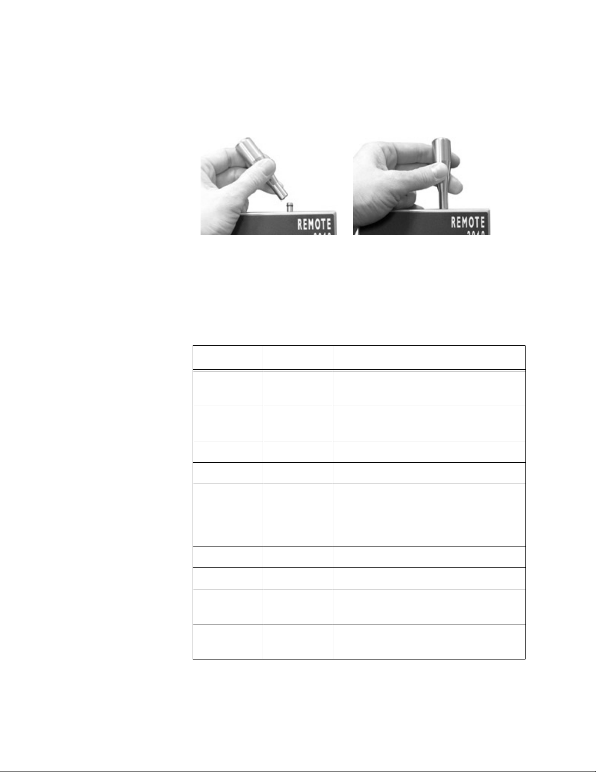
Installation Your instrument(s) can be easily prepared for use by performing the
steps below. Depending on the unit’s output, each instrument can be
located up to 1000 feet (330 meters) from the counting device.
1. Locate instrument(s) in areas to be sampled.
2. Attach barbed fitting to top inlet.
Figure 3-6 Attaching the Fitting
3. Attach sample tubing to barbed (top) fitting.
Figure 3-7 Attach sample tubing to inlet
3-4 248083201-1 Rev 6
Getting Started
4. Attach tubing from external vacuum source to the barbed fitting on
the bottom of the unit.
Installing an
Isokinetic
An Isokinetic probe can be attached directly to the unit. Screw the
probe directly onto the inlet.
Probe
Figure 3-8 Installing Probe Directly on Barb
Data Port Connector J10 on the bottom of the instrument is used to communicate
with your Facility Management System. Signals at this port include two
4-20mA data channels, an external alarm channel, power and ground.
Table 3-1 J10 with Status Data Connector Pinouts
Pin Number Signal Range
1 Chan 1 1) 4-20mA particle count levels
2) 2mA Service Alert level
2 Chan 2 1) 4-20mA particle count levels
2) 2mA Service Alert level
3 * VLOOP +15VDC to +30VDC
4 Ground
5 Status (if
signal is
available Figure 3-4)
6 Ground
7 * VPWR +6VDC to +30VDC
8 External
Alarm (-)
9 External
Alarm (+)
* If the application allows, VLOOP and VPWR may be connected to
the same source. In that case, the VPWR is +15VDC to +30VDC.
1) 4mA: no Alarm, no Service Alert
2) 12mA: Channel overflow Alarm
3) 20mA: SERVICE Alert
Continuity with Pin 9 if ALARM.
+40VDC at 1A maximum
248083201-1 Rev 6 3-5

Lighthouse REMOTE 2012, 3012, 5012, 3102, 5102 Operating Manual
Table 3-2 J10 without Status Data Connector Pinouts
Pin Number Signal Range
1 Chan 1 1) 4-20mA particle count levels
2) 2mA Service Alert level
2 Chan 2 1) 4-20mA particle count levels
2) 2mA Service Alert level
3 * VLOOP +15VDC to +30VDC
4 Ground
5N/A -
(Figure 3-5)
6 Ground
7 * VPWR +6VDC to +30VDC
8 External
Continuity with Pin 9 if ALARM.
Alarm (-)
9 External
+40VDC at 1A maximum
Alarm (+)
* If the application allows, VLOOP and VPWR may be connected to
the same source. In that case, the VPWR is +15VDC to +30VDC.
Included with the instrument is a plug to connect the J10 connector to
your Facilities Monitoring System.
Figure 3-9 J10 Connector With Plug Attached
3-6 248083201-1 Rev 6

Getting Started
Applications Figure 3-10 and Figure 3-11 illustrate how to wire J10 for a two-wire or
a three-wire system.
When feature is
available, pin 5
is STATUS
Figure 3-10 Application for a Two Wire System
248083201-1 Rev 6 3-7

Lighthouse REMOTE 2012, 3012, 5012, 3102, 5102 Operating Manual
When feature is
available, pin 5
is STATUS
Figure 3-11 Application for a Three Wire System
3-8 248083201-1 Rev 6

00
4 Programming
General The REMOTE 2 Series family of instruments can be programmed in
either of two ways. The DIP switches can be used to set the Sampling
Time and Range values. If an ASCII terminal is connected to the
instrument, it can program the unit’s Sample Time, Range, Service
High, Service Low, Alarm Threshold and Suppress Alarm Count.
This chapter contains the information needed to program the
instrument to meet your needs.
DIP Switches The DIP switches are behind a panel under the Data connector J10.
Figure 4-1 Panel Covering the DIP Switches
Remove the two Phillips head screws to expose the DIP switches.
248083201-1 Rev 6 4-1

Lighthouse REMOTE 2012, 3012, 5012, 3102, 5102 Operating Manual
1 2 3 4 5 6 7 8
Switch
Numbers
DIP Switch
Settings
Note: The DIP Switches
must be set before the unit
is powered ON.
Figure 4-2 Panel Removed, Switches Exposed
GENERAL DEFINITIONS
OFF (DOWN) = 0, ON (UP) = 1
Switch Number1234 5678
Data 0000:0000
At Startup:
0000:0000==> Program Mode (ASCII terminal)
0000:0001==> Immediate Startup using last stored parameters
Anything Else==> DIP Switch Mode
Time:Range
When a DIP switch is set to any of the pre-programmed values listed
below and power applied to the instrument, information is echoed back
to the terminal, if connected.
These settings affect time and range only. All other parameters, such
as Alarm Value and Suppress Alarms, are left at their previous settings.
Time is the sampling time in seconds. The Range setting is applied to
both channels.
4-2 248083201-1 Rev 6

DIP Switch Settings and Meanings
1000:1000 ==> 6 seconds, 1000 counts
1000:0100 ==> 6 seconds, 10,000 counts
1000:0010 ==> 6 seconds, 100,000 counts
0100:1000 ==> 60 seconds, 1000 counts
0100:0100 ==> 60 seconds, 10,000 counts
0100:0010 ==> 60 seconds, 100,000 counts
0010:1000 ==> 600 seconds, 1000 counts
Programming
0010:0100 ==> 600 seconds, 10,000 counts
0010:0010 ==> 600 seconds, 100,000 counts
If the user chooses DIP switch combinations other than the ones
specified above, the unit will default to a sample time of 300 seconds,
Range1 and Range2 to 100,000 counts.
Procedure to Set DIP Switches
1. Remove power from the instrument.
2. Set the DIP Switches to the desired Time and Range, using the
information above.
3. Apply power to the instrument.
Example Startup Echo, Reading DIP Switches:
Lighthouse Remote Instrument (4-20mA):
- reading dip switch:
Sample Time = 60 secs
Range1= 10000.
Range2= 1000.
Alarm Threshold = 750 counts
Suppress Alarms = 2
Service High = 3500 mV
Service Low = 125 mV
248083201-1 Rev 6 4-3
Lighthouse REMOTE 2012, 3012, 5012, 3102, 5102 Operating Manual
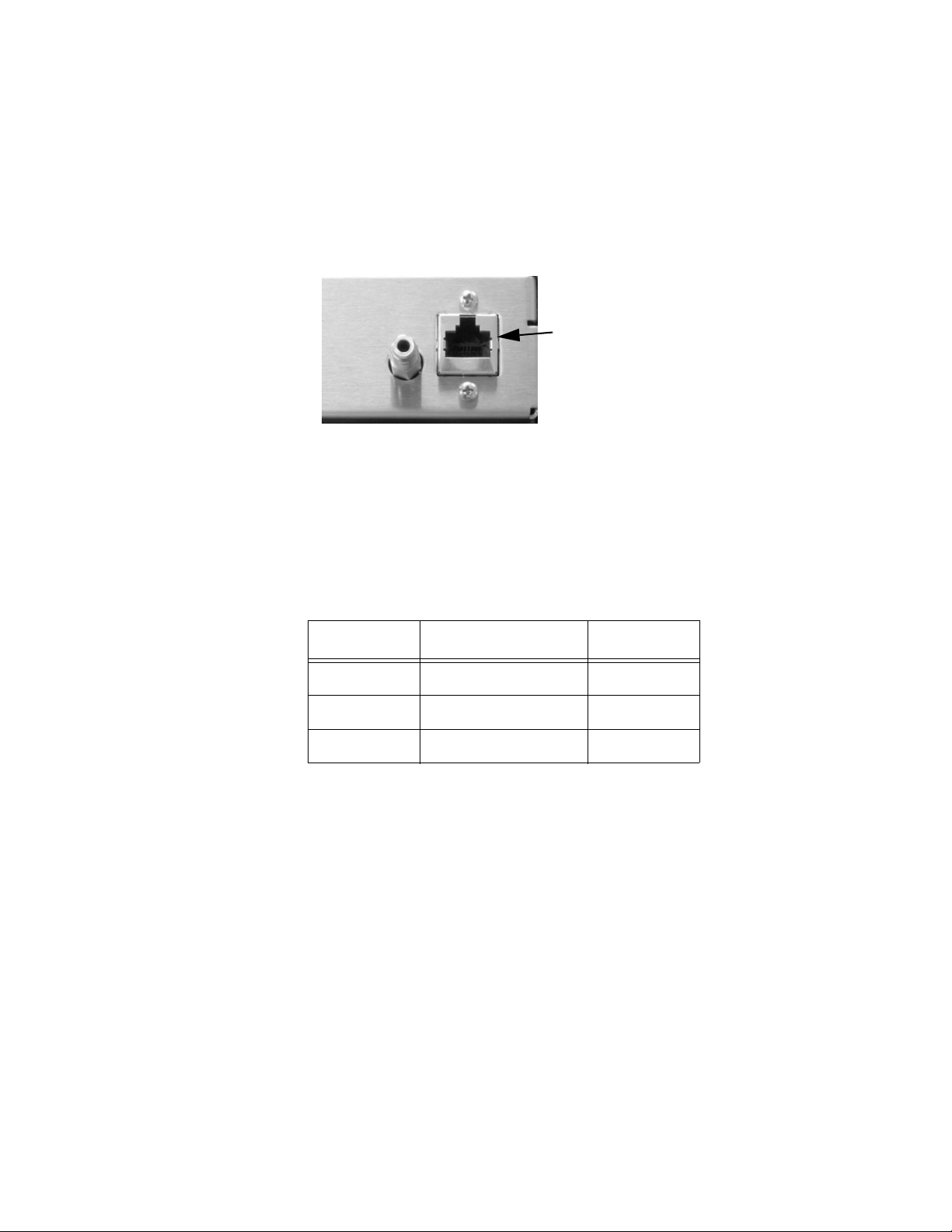
Connecting
the
Instrument to
a Terminal
The RJ-45 connector on the instrument (marked "Programming Port" in
Figure 4-3) is used to interconnect the unit with a COM port on a
desktop or laptop PC. Once connected and set up as an ASCII
terminal, the PC can be used to program and/or monitor the instrument
settings.
Programming
Port
8 1
Figure 4-3 The Programming Port, Showing Pin Numbers
A modular adapter, RJ-45 to DB-9, is available from Lighthouse. The
pinouts of the adapter are shown in the table below:
Table 4-1 RJ-45 to DB-9 Connections
RJ-45 Pin Signal Name DB-9 Pin
1TX2
2RX3
8 Ground 5
To connect the instrument to a computer:
1. Remove power from the instrument.
2. Connect the RJ-45 end of the adapter cable to the Programming
Port on the instrument.
3. Connect the DB-9 end of the cable to a COM (Serial) Port on your
computer.
4. Open Hyperterminal on your computer.
5. Configure the COM Port settings as follows. Any available COM
Port may be used:
4-4 248083201-1 Rev 6
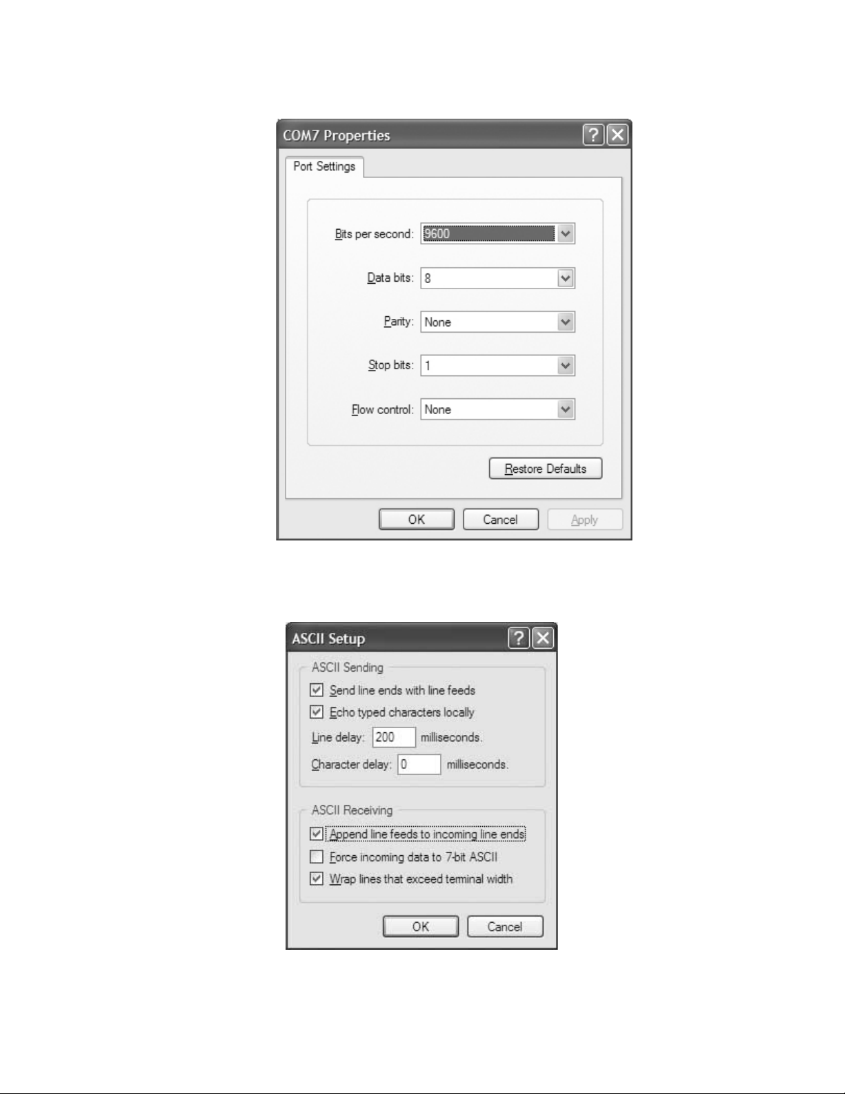
Programming
Figure 4-4 COM Port Properties
6. Configure the ASCII settings as follows:
Figure 4-5 ASCII Settings
248083201-1 Rev 6 4-5

Lighthouse REMOTE 2012, 3012, 5012, 3102, 5102 Operating Manual
7. Ensure that all DIP Switches are set to 0 (OFF/DOWN).
Power Up If DIP Switches all = 0 ==> Program Mode:
During the first 20 seconds after power is applied, the unit waits for
programming commands. If no commands are received within that
time, the instrument recalls its last stored parameters (or default
settings) and continues to use them.
If a programming command is received within the first 20 seconds, the
command is examined and, if valid, the parameters are set and stored in
non-volatile memory, overwriting the previous parameters for that
command.
The instrument waits another 20 seconds for the next command and the
process repeats for each command that is sent. After the last command,
the timer times out and the instrument is loaded with the commands
that were issued. Old parameters are used if they were not modified
during this session.
Session
Example
Note: Upper case V.
The < and > characters are
needed; they mark the
beginning and end of the
command.
Once programmed, the instrument retains its settings until they are
modified. The user can set DIP Switch 8 to ON (UP, 1) to eliminate the
20 second timer when the unit is next powered up.
Lighthouse recommends that, before powering up the instrument, you
make a list of the commands and parameters you want to use, thus
avoiding an unwanted timeout.
The following steps should be performed whenever you want to
program the instrument or check its settings using the ASCII terminal.
1. Set all DIP Switches to OFF (DOWN, 0) to program the instrument
and connect it to the ASCII terminal.
2. Apply power to the instrument. The Hyperterminal programming
prompt is sent from the unit.
3. Type: <V> -- this is Verbose mode. This must be the first
command sent if you wish to see responses from the
instrument
4. Type: <?> -- the unit’s current settings are displayed.
<?>
Flow Rate = 0.1 cfm
Sample Time = 5 secs
Range1= 10000.
4-6 248083201-1 Rev 6

Programming
Range2= 1000.
Service High = 3000 mV
Service Low = 145 mV
Alarm Channel = 1
Alarm Threshold = 1000 counts
Suppress Alarms = 2
Channel 1 = 0.3
Channel 2 = 0.5
5. Type: <m1> -- the unit’s menu is displayed to show commands to
use to change parameters.
<m1>
*** User Menu ***
<?> Display Parameters
<V> Verbose Mode
<sa> Start Counting
<sb> Stop Counting
<gv> Get Version Number
<ra#> Set Range 1 (counts)
<rb#> Set Range 2 (counts)
<ta#> Set Sample Seconds
<aa#> Set Alarm Channel #
<ab#> Set Alarm Threshold (# of counts)
<ae#> Set Alarm Suppression #
ASCII
Programming
Syntax
6. The instrument will wait 20 seconds after the last command is sent,
then begin sampling
Using a simple ASCII protocol, the REMOTE 3012 family of
instruments can be programmed from an ASCII terminal (i.e. Hyper
Terminal). The protocol format is based on a start character, followed
by a command, which is then followed by a terminating character. Any
characters before the start character, or after the terminating character
are ignored. White spaces between command character and command
parameter are ignored.
Command Structure
The commands are defined as single case-sensitive ASCII characters.
Format is defined as shown on page 8.
248083201-1 Rev 6 4-7

Lighthouse REMOTE 2012, 3012, 5012, 3102, 5102 Operating Manual
Note: The < and >
characters are part of the
command and must be
typed. The brackets [ and ]
are field delimiters and are
not typed.
Note:
characters are lower case,
except for the V (verbose).
All command
<x[yyyy]>
where:
< = Start Character
x = Command Character
yyyy = Optional Command Parameter
> = Terminating Character
Handshake
Upon execution of the command, and assuming you have typed <V>
for Verbose, the REMOTE instrument will send a response based on
the value of the counts, suppress alarms, and alarm status. Examples of
responses are listed below:
<ERR> = Error in Command String.
-or-
Sample: ch1-2: 0, 0 Range1= 5000, Range2= 2500.
When the unit is powered up, it sets up the counters and timers, and
starts reporting data. The data will be similar to this example:
Sample: ch1-2: 0, 0 Range1= 5000, Range2= 2500.
Sample: ch1-2: 0, 0 Range1= 5000, Range2= 2500.
Protocol
Protocol is defined through an RS-232 interface. The hardware
protocol is defined as:
Baud Rate: 9600
Data Bits: 8
Stop Bits: 1
Parity: None
Flow Control: None
4-8 248083201-1 Rev 6

Command Set
VERBOSE MODE
Note: Upper case V <V>
Normally, VERBOSE MODE is off and the computer responds with
<OK> after each command is received and correctly implemented.
Turning on VERBOSE MODE tells the computer to echo back the
information to the screen.
VERBOSE MODE is required in order to program the device. It is not
required to run the counter.
GET CURRENT SETTINGS
<?>
Shows current parameter settings.
Programming
Type:
<?>
Response:
<?>
Flow Rate = 0.1 cfm
Sample Time = 5 secs
Range1= 10000.
Range2= 1000.
Service High = 3000 mV
Service Low = 145 mV
Alarm Channel = 1
Alarm Threshold = 1000 counts
Suppress Alarms = 2
Channel 1 = 0.3
Channel 2 = 0.5
DISPLAY MENU OF COMMANDS
<m1>
Shows menu of commands.
248083201-1 Rev 6 4-9

Lighthouse REMOTE 2012, 3012, 5012, 3102, 5102 Operating Manual
Type:
<m1>
Response:
<m1>
*** User Menu ***
<?> Display Parameters
<V> Verbose Mode
<sa> Start Counting
<sb> Stop Counting
<gv> Get Version Number
<ra#> Set Range 1 (counts)
<rb#> Set Range 2 (counts)
<ta#> Set Sample Seconds
<aa#> Set Alarm Channel #
<ab#> Set Alarm Threshold (# of counts)
<ae#> Set Alarm Suppression #
START/STOP COUNTING MODE
START Counting
<sa>
This will start the device’s counting mode. When implemented, the
unit will wait until the sample time passes before displaying the sample
data.
Type:
<sa>
Response:
<sa>START
Sample: ch1-2: 0, 0 Range1= 10000, Range2= 5000.
Sample: ch1-2: 0, 0 Range1= 10000, Range2= 5000.
STOP Counting
<sb>
This will stop the device’s counting mode.
4-10 248083201-1 Rev 6

Type:
<sb>
Response:
<sb>STOP
GET CURRENT VERSION NUMBER
<gv>
Shows current version number of the device firmware.
Type:
<gv>
Response:
<gv> Version: 010
Programming
Note: Range 1 should
always be greater than or
equal to Range 2; Range 2
should never be greater
than Range 1.
When using the DIP switch
programming, both
channels are set to the
same range value.
SET CHANNEL RANGES
<ra#> -- sets upper range of channel 1 where # is the range value
<rb#> -- sets upper range of channel 2 where # is the range value
Sets upper limit to counting range. The upper limit will be equal to
20mA, and the lower range will always be 0 counts = 4 mA. If the
counts exceed range limit, the counts will be set to the range limit. The
maximum range is 10,000,000.
Type:
<ra10000>
Response:
<ra10000>Range1= 10000.
Type:
<rb7500>
Response:
<rb7500>Range2= 7500.
248083201-1 Rev 6 4-11

Lighthouse REMOTE 2012, 3012, 5012, 3102, 5102 Operating Manual
SET SAMPLE TIME (seconds)
Note: Sample times <5
seconds are not
recommended.
<ta#>
Sets sample time in # seconds, where # >1 and nnnn < 3600.
Type:
<ta30>
Response:
<ta30>Sample Time = 30 secs
SET ALARM CHANNEL
<aa#>
Sets the alarm channel to channel 1 or 2.
Type:
<aa1>
Response:
<aa1>Alarm Channel= 1
SET ALARM THRESHOLD
<ab#>
Sets Alarm High count threshold for the configured alarm channel.
Value # must be less than range in order to set the threshold. Set the
value to 0 (zero) to disable alarm.
If the count for the configured alarm channel exceeds the threshold
then:
• The red SERVICE indicator on the instrument blinks.
• The EXTERNAL ALARM relay, described below, is set.
• The alarm alert will be seen on the ASCII terminal as illustrated
next:
Type:
<ab1000>
4-12 248083201-1 Rev 6

Programming
Response:
<ab1000>Alarm Threshold= 1000 counts
Hyperterminal Alarm Alert without Alarm Suppression:
Note: The field bk= 429
in this example is the
"backlight" function which
is a measurement of
scattered light in the
instrument. See
SET_SERVICE_HIGH and
SET_SERVICE_LOW
In this example, the Alarm Suppress is disabled (0).
secs=1: ch1-2: 285, 48 , bk= 429
secs=2: ch1-2: 487, 89 , bk= 429
secs=3: ch1-2: 1699, 1033 , bk= 1049
secs=4: ch1-2: 2572, 1320 , bk= 434
secs=5: ch1-2: 3337, 1575 , bk= 429
Sample: ch1-2: 3337, 1575 Range1= 10000, Range2= 5000.
Alarms: Threshold= 1000, Channel= 1, # in a row=1
secs=1: ch1-2: 615, 228 , bk= 434, alarm alert.
secs=2: ch1-2: 1115, 382 , bk= 429, alarm alert.
secs=3: ch1-2: 1595, 502 , bk= 429, alarm alert.
secs=4: ch1-2: 2029, 637 , bk= 429, alarm alert.
secs=5: ch1-2: 2381, 738 , bk= 429, alarm alert.
Sample: ch1-2: 2381, 738 Range1= 10000, Range2= 5000.
Alarms: Threshold= 1000, Channel= 1, # in a row=2
SET ALARM SUPPRESSION
<ae#>
Sets the alarm suppression for the configured alarm channel. The
number of alarm conditions have to be greater than # in order to turn on
the Alarm Relay.
For example, if Alarm Suppress is set to 2, then the device won’t report
an alarm condition via the external alarm output or the flashing service
light until the 3rd consecutive alarm condition.
Type:
<ae2>
Response:
<ae2>Suppress Alarms = 2
Hyperterminal Alarm Alert with Alarm Suppression:
In this example, the Alarm Suppress is set to 2.
248083201-1 Rev 6 4-13

Lighthouse REMOTE 2012, 3012, 5012, 3102, 5102 Operating Manual
<ae2>Suppress Alarms = 2
secs=1: ch1-2: 0, 0 , bk= 429
secs=2: ch1-2: 681, 430 , bk= 2558
secs=3: ch1-2: 1629, 886 , bk= 444
Sample: ch1-2: 1629, 886 Range1= 10000, Range2= 5000.
Note: The first line
starting with "Alarms" (in
boldface) shows what the
current alarm threshold is,
which channel is set for
alarming and how many
alarm conditions in a row
have occurred.
Alarms: Threshold= 1000, Channel= 1, # in a row=1
secs=1: ch1-2: 828, 517 , bk= 1640
secs=2: ch1-2: 1861, 1230 , bk= 434
secs=3: ch1-2: 3149, 2177 , bk= 449
Sample: ch1-2: 3149, 2177 Range1= 10000, Range2= 5000.
Alarms: Threshold= 1000, Channel= 1, # in a row=2
secs=1: ch1-2: 450, 126 , bk= 434
secs=2: ch1-2: 1279, 530 , bk= 444
secs=3: ch1-2: 1875, 678 , bk= 439
Sample: ch1-2: 1875, 678 Range1= 10000, Range2= 5000.
Alarms: Threshold= 1000, Channel= 1, # in a row=3
Note: The "alarm alert"
(in boldface) doesn’t
display until after the 3rd
consecutive alarm
condition; the external
alarm light goes on at this
point as well.
Service High
and Service
Low
Note: The "normal"
levels seen in these "bk"
fields are examples only
and are not necessarily
what you will see with your
instrument.
secs=1: ch1-2: 697, 131 , bk= 439, alarm alert.
secs=2: ch1-2: 1215, 227 , bk= 434, alarm alert.
secs=3: ch1-2: 1505, 302 , bk= 439, alarm alert.
Sample: ch1-2: 1505, 302 Range1= 10000, Range2= 5000.
Alarms: Threshold= 1000, Channel= 1, # in a row=4
Service High and Service Low are the voltage levels at which the
Service Light will go on. Those levels are compared to the "Backlight"
measurement (seen as the bk= 1455 field) in every sample period. If
the Backlight measurement is greater than Service High or less than
Service Low, then:
• the service alert appears as seen in the following Hyperterminal
Service Alert example:
• J10 pins 1 and 2 (Chans 1 and 2) = 2mA
• the Service Light is turned on
The default Service High threshold is 3500.
Hyperterminal Service Alert Example:
secs=1: ch1-2: 667, 214 , bk= 463
secs=2: ch1-2: 2262, 1395 , bk= 449
secs=3: ch1-2: 2890, 1608 , bk= 434
secs=4: ch1-2: 4719, 2983 , bk= 4995, service alert.
4-14 248083201-1 Rev 6

secs=5: ch1-2: 4719, 2983 , bk= 4995, service alert.
Sample: ch1-2: 4719, 2983 Range1= 10000, Range2= 5000.
Alarms: Threshold= 1000, Channel= 1, # in a row=1
Service Menu The Service Menu is available by typing <ms>.
Type:
<ms>
Response:
<ms>
*** Service Menu ***
<ia> Don't show 1 sec data
<ib> Show 1 sec data
<gb> Get Bkgnd
DON’T SHOW 1 SEC DATA
Programming
<ia>
Turns OFF 1 second data display.
Type:
<ia>
Response:
<ia>Don't show 1 sec data.
After starting the counter with <sa>, the device will wait until the
sample time interval passes before displaying the first sample.
SHOW 1 SEC DATA
<ib>
Turns ON 1 second data display.
Type:
<ib>
Response:
<ib>Show 1 sec data.
248083201-1 Rev 6 4-15

Lighthouse REMOTE 2012, 3012, 5012, 3102, 5102 Operating Manual
After starting the counter with <sa>, the device will show the samples
collecting every second.
secs=1: ch1-2: 0, 0. , bk= 424
secs=2: ch1-2: 0, 0. , bk= 424
secs=3: ch1-2: 0, 0. , bk= 424
secs=4: ch1-2: 0, 0. , bk= 424
secs=5: ch1-2: 1, 0. , bk= 424
This mode can be used to view the data on a second-by-second basis
for troubleshooting.
GET BACKGROUND LIGHT VALUE
<gb>
Displays the current background value in milli-volts (mV).
4-16 248083201-1 Rev 6

00
5 Technical Data
Introduction This chapter describes the operation and programming of the
instrument.
Control
Design
Setup
Start
Figure 5-1 States for the 3012, 5012, 3102, 5102 Particle Counter
START
• Starts microprocessor, and initializes hardware.
SETUP
Count Timer
Output
Alarm
Counts
• If DIP Switches all = 0 ==> Program Mode:
During the first 20 seconds, the unit waits for programming
commands. If any programming commands are received within the
first 20 seconds, those commands will be examined and executed.
If the commands are valid, the parameters will be set. If no
248083201-1 Rev 6 5-1

Lighthouse REMOTE 2012, 3012, 5012, 3102, 5102 Operating Manual
commands are received (all DIP switches = 0) or if an invalid
command is received, the instrument will recall its last stored
parameters (or default settings) and continue to use them.
• If DIP Switches = 0000 0001 ==> Use last stored parameters
With the DIP switches set with this value, the instrument will start
up immediately using the last stored parameters.
Startup Example:
Lighthouse Remote Instrument (4-20mA):
- reading dip switch:
Sample Time = 60 secs
Range1= 10000.
Range2= 1000.
Alarm Threshold = 750 counts
Suppress Alarms = 2
Service High = 3500 mV
Service Low = 125 mV
• DIP Switches = Anything other than (0000 0000 or 0000 0001)
The DIP switch settings will be read and interpreted. If the
combination is valid, those parameters will be chosen. Otherwise,
sample time of 300 seconds and 100,000 counts will be used.
COUNT
The instrument uses setup parameters to run, collect data, and output
count and alarm data. 0 counts will be represented by 4mA, and counts
equal to upper range will equal 20mA. The current output will have a
direct linear relationship to the range.
• Iout= 16mA(counts/ range) + 4mA
• Vout= Iout(R-load)
• If a Service Alert occurs, both channels are set to 2mA.
TIMER
Keeps track of time relative to sample seconds, and outputs sample data
every SampleSecs.
5-2 248083201-1 Rev 6

Technical Data
OUTPUT
• Counts are output on CH1 and CH2 lines in 4-20 mA current.
• If STATUS feature is available and counts become greater than the
alarm threshold, after a "suppress" of # of consecutive alarm
conditions, STATUS (pin 5) is set to 12mA and the ALARM relay
is turned ON.
• If STATUS feature is not available and counts become greater than
the alarm threshold, after a "suppress" # of consecutive alarm
conditions, the ALARM relay is turned ON.
• If STATUS feature is available and Background Light laser voltage
exceeds the ServiceHigh or ServiceLow limit or when the laser
optics are dirty, STATUS (pin 5) is set to 20mA.
ALARM
If the CH1 or CH2 count exceeds the programmed ALARM threshold,
• The red SERVICE indicator on the instrument blinks.
• The EXTERNAL ALARM relay, described below, is set.
• If STATUS feature is available, STATUS (pin 5) is set to 12mA.
SERVICE ALERT
If the service/background light voltage is greater than the Service High,
or less than Service Low limits, then:
• CH1 and CH2 outputs are set to 2mA.
• The red SERVICE indicator on the instrument is turned on steady.
• If STATUS feature is available and pin 5 = 4 mA ==> No Alarms
and No Service Alerts.
EXTERNAL ALARM
An ALARM condition, as described above, also closes a relay inside
the instrument. Contacts of that relay are connected to the DATA
connector, pins 8 (-) and 9 (+). The user may use an external power
supply and a buzzer or light stick to provide local indication of an
alarm condition. The contacts are rated at 40VDC, 1A maximum.
248083201-1 Rev 6 5-3

Lighthouse REMOTE 2012, 3012, 5012, 3102, 5102 Operating Manual
5-4 248083201-1 Rev 6

00
6 Maintenance
Procedures
Introduction This chapter provides instructions for routine maintenance that may be
required for your REMOTE 2012, 3012, 5012, 3102 or 5102
instrument.
The maintenance procedures described in this chapter are not required
on regular or prescribed intervals and should be performed only if you
have reason to question the data you are receiving from the instrument.
Safety Before performing any of the maintenance tasks described in this
chapter, read Chapter 1 of this manual and become familiar with the
warnings and caution labels.
Calibration To maintain optimum performance of this instrument, it should be re-
calibrated annually by a Lighthouse Authorized Service Provider.
Purge Count
Test
This section will provide you with the procedure to check the counter
for zero counts. A purge filter must be attached to the instrument and
six (6) five (5) minute samples must be taken. There should be no more
than 1 count on average per five-minute sample.
1. Disconnect power from the instrument.
2. Connect the Purge filter to the sample inlet.
3. Apply power to the instrument.
4. Configure the unit to run one 30-minute sample.
5. Run the 30-minute sample. This time allows the unit to warm up
and purge any residual particles that might be inside the
instrument.
6. Stop sampling.
248083201-1 Rev 6 6-1

Lighthouse REMOTE 2012, 3012, 5012, 3102, 5102 Operating Manual
7. Program the unit for 5-minute sample time and 10-second hold.
8. Run six 5-minute samples.
9. If an average of more than one count per five-minute period is
reported, run another 30-minute sample to purge it and repeat
Step 8.
10. If the instrument has met the requirement of the Purge Count test,
return the instrument to its normal location and operating status.
Fault Isolation If the instrument does not pass the Purge Count test, please perform the
following procedure:
1. Check the data over the last 6 five-minute sample times.
2. If sporadic counts over all channels are occurring, the unit may
still have particles inside it. Allow the unit to sample overnight
with the purge filter attached before retesting it. If the counts are
still high after the overnight purge, call Lighthouse Technical
Support for assistance.
3. If the data shows consistent counts in the smallest channel only,
the instrument may have electrical problems. Call your
Lighthouse Service Representative for assistance.
6-2 248083201-1 Rev 6

00
A Limited Warranty
Limitation Of Warranties:
A. Lighthouse Worldwide Solutions (LWS) warrants that all
equipment shall be free from defects in material and
workmanship under normal use for a period of two years from
date of shipment to Buyer except that LWS does not warrant that
operation of the software will be completely uninterrupted or
error free or that all program errors will be corrected. Buyer shall
be responsible for determining that the equipment is suitable for
Buyer’s use and that such use complies with any applicable
local, state, or federal law. Provided that Buyer notifies LWS in
writing of any claimed defect in the equipment immediately
upon discovery and any such equipment is returned to the
original shipping point, transportation charges prepaid, within
two years from date of shipment to Buyer and upon examination
LWS determines to its satisfaction that such equipment is
defective in material or workmanship, i.e. contains a defect
arising out of the manufacture of the equipment and not a defect
caused by other circumstances, including, but not limited to
accident, misuse, unforeseeable use, neglect, alteration,
improper installation, improper adjustment, improper repair, or
improper testing, LWS shall, at its option, repair or replace the
equipment, shipment to Buyer prepaid. LWS shall have
reasonable time to make such repairs or to replace such
equipment. Any repair or replacement of equipment shall not
extend the period of warranty. If the Instrument is modified or in
any way altered without the explicit written consent of LWS then
the warranty is null and void. This warranty is limited to a period
of two years, except as noted below, without regard to whether
any claimed defects were discoverable or latent on the date of
shipment. The length of warranty for pumps in hand held particle
counters is one (1) year. Batteries and accessories with all
products are warranted for one (1) year. Fuses and purge filters
carry no warranty. If a third party battery is used in the product,
the product warranty is null and void. If the battery is charged by
a third party battery charger the battery warranty is null and void.
B. If Buyer shall fail to pay when due any portion of the purchase
price or any other payment required from Buyer to LWS under
this contract or otherwise, all warranties and remedies granted
under this Section may, at LWS’s option, be terminated.
C. THE FOREGOING WARRANTY IS EXCLUSIVE AND IN
LIEU OF ALL OTHER REPRESENTATIONS, WARRANTIES
AND COVENANTS, EXPRESS OR IMPLIED WITH
RESPECT TO THE EQUIPMENT AND ANY DEFECTS
THEREIN OF ANY NATURE WHATEVER, INCLUDING
AND WITHOUT LIMITATION WARRANTIES OF
MERCHANTABILITY OR FITNESS FOR A PARTICULAR
PURPOSE. LWS SHALL NOT BE LIABLE FOR, AND
BUYER ASSUMES ALL RISK OF, ANY ADVICE OR
FAILURE TO PROVIDE ADVICE BY LWS TO BUYER
REGARDING THE EQUIPMENT OR BUYERS USE OF THE
SAME. UNDER NO CIRCUMSTANCES SHALL LWS BE
LIABLE TO BUYER UNDER ANY TORT, NEGLIGENCE,
STRICT LIABILITY, OR PRODUCT LIABILITY CLAIM
AND BUYER AGREES TO WAIVE SUCH CLAIMS. LWS’s
SOLE AND EXCLUSIVE LIABILITY AND BUYERS SOLE
AND EXCLUSIVE REMEDY, FOR ANY
NONCONFORMITY OR DEFECT IN THE PRODUCTS OR
ANYTHING DONE IN CONNECTION WITH THIS
CONTRACT, IN TORT, (INCLUDING NEGLIGENCE),
CONTRACT, OR OTHERWISE, SHALL BE AS SET FORTH
IN THE SUBSECTION A HEREOF AS LIMITED BY
SUBSECTION B HEREOF. THIS EXCLUSIVE REMEDY
SHALL NOT HAVE FAILED OF ITS ESSENTIAL PURPOSE
(AS THAT TERM IS USED IN THE UNIFORM
COMMERCIAL CODE) PROVIDED THAT THE SELLER
REMAINS WILLING TO REPAIR OR REPLACE
DEFECTIVE EQUIPMENT (AS DEFINED IN SUBSECTION
A) WITH A COMMERCIALLY REASONABLE TIME
AFTER RECEIVING SUCH EQUIPMENT. BUYER
SPECIFICALLY ACKNOWLEDGES THAT SELLER’S
PRICE FOR THE EQUIPMENT IS BASED UPON THE
LIMITATIONS OF LWS’S LIABILITY AS SET FORTH IN
THIS CONTRACT.
Warranty Of Repairs After
Initial Two (2) Year Warranty:
A. Upon expiration of the initial two-year warranty, all parts and
repairs completed by an authorized Lighthouse repair technician
are subject to a six (6) month warranty.
B. Other than the above, LWS makes no warranty of any kind,
expressed or implied, except that the products manufactured and
sold by LWS shall be free from defects in materials and
workmanship and shall conform to LWS’s specifications; Buyer
assumes all risk and liability resulting from use of the products
whether used singly or in combination with other products. If
instrument is modified or in any way altered without the explicit
written consent of LWS, then the warranty is null and void.
C. WARRANTY REPAIRS SHALL BE COMPLETED AT THE
FACTORY, BY AN AUTHORIZED SERVICE LOCATION,
BY AN AUTHORIZED SERVICE TECHNICIAN, OR ON
SITE AT BUYER’S FACILITY BY A LIGHTHOUSE
AUTHORIZED EMPLOYEE. BUYER PAYS FREIGHT TO
FACTORY; SELLER WILL PAY STANDARD RETURN
FREIGHT DURING THE WARRANTY PERIOD. BUYER
MAY SELECT A FASTER METHOD OF SHIPMENT AT ITS
OWN EXPENSE.
248083201-1 Rev 6 A-1

Lighthouse REMOTE 2012, 3012, 5012, 3102, 5102 Operating Manual
A-2 248083201-1 Rev 6

00
Index
A
Accessories 2-2
Alarm 5-3
Alarm Channel 4-12
Alarm Suppression 4-13
Alarm Threshold 4-12
Applications, two and three wire 3-7
ASCII Programming
Command Set 4-9
Command Structure 4-7
Display Menu of Commands 4-9
Don’t Show 1 Second Data 4-15
Get Background Light Value 4-16
Get Current Setings 4-9
Get Current Version Number 4-11
Handshake 4-8
Protocol 4-8
Service Menu 4-15
Set alarm Channel 4-12
Set Alarm Suppression 4-13
Set Alarm Threshold 4-12
Set Channel Ranges 4-11
Set Sample Time 4-12
Show 1 Sec Data 4-15
Start/Stop Counting Mode 4-10
Syntax 4-7
Verbose Mode 4-9
B
COM Port connection 4-4
Command Structure 4-7
Communication Modes 2-3
Connecting the Instrument to a Terminal 4-4
Connections 3-3
Control Design 5-1
Alarm 5-3
Count 5-2
External Alarm 5-3
Output 5-3
Service Alert 5-3
Setup 5-1
Start 5-1
Timer 5-2
Counting Efficiency 2-3
Current Settings 4-9
Current Version Number 4-11
D
Data Port 3-5
Description, general 2-1
Dimensions 2-3
DIP Switches 4-1
=0 at Power Up 4-6
Meanings 4-3
procedure 4-3
Settings 4-2
Don’t Show 1 Second Data 4-15
Background Light Value 4-16
E
External Alarm 5-3
C
Calibration 2-3
Channel Threshold 2-3
Collection Optics 2-2
248083201-1 Rev 6 I-1
External vacuum source 3-5
F
Flow Rate 2-3

Lighthouse REMOTE 2012, 3012, 5012, 3102, 5102 Operating Manual
Front panel lights 3-2
I
Initial Inspection 3-1
Installation 3-4
Installing an Isokinetic Probe 3-5
Interpreting indicators 3-2
Introduction
Description, general 2-1
Overview 2-1
isokinetic probe 3-5
L
Laser Diode 2-2
Laser Source 2-3
M
Menu of Commands 4-9
O
Operating Temp/RH 2-3
Operation 3-2
Interpreting indicators 3-2
Overview 2-1
Sample Time 4-12
Service
High and Low 4-14
Service Alert 5-3
Service Menu 4-15
Set Channel Ranges 4-11
Setting DIP Switches 4-2
Shipping instructions 3-1
Show 1 Sec Data 4-15
Size Ranges 2-3
Specifications 2-3
Start Counting 4-10
Startup using defaults 5-2
Startup using last stored paramaters 5-2
Stop Counting 4-10
Storage Temp/RH 2-3
T
Terminal
ASCII Settings 4-5
COM Port Properties 4-5
Command Structure 4-7
Programming Syntax 4-7
Session Example 4-6
Terminal, Connecting To 4-4
Three wire systems 3-7
Troubleshooting, Zero Count 6-2
Two Wire Systems 3-7
P
Particle Detection 2-2
Particles, sizes 2-1
Power 2-3
Power Up, DIP Switches = 0 4-6
Programming
DIP Switches 4-2
S
Safety 1-1, 6-1
Electrostatic safety information 1-2
Laser safety information 1-1
I-2 248083201-1 Rev 6
U
Unpacking 3-1
V
Vacuum Requirements 2-3
Verbose Mode 4-9
W
Warning
Electrostatic Discharge 1-2
Infrared Radiation 1-1

Weight 2-3
Z
Zero Count Check
Troubleshooting 6-2
Zero Count Level 2-3
Index
248083201-1 Rev 6 I-3

Lighthouse REMOTE 2012, 3012, 5012, 3102, 5102 Operating Manual
I-4 248083201-1 Rev 6

00

 Loading...