

Lighthouse Raymarine gS95, Raymarine gS125, Raymarine gS165, Raymarine gS 195 Installation And Operation Instruction Manual

gS Series
Installation and operation
instructions
English
Date: 01-2015
Document number: 81344-7-EN
© 2015 Raymarine UK Limited
R
elease 13


Documentandsoftwarechanges(gSSeries)
Thefollowingtablesdescribethemainchangesthathavebeenmadesincethelastreleaseofboththe
productsoftwareandthisdocument.
•Applicablesoftwareversion:LightHouseII—Release13.xx
•Applicabledocuments:81344–7
•Applicableproducts:gS95/gS125/gS165/gS195.
Newfeatures
Description
Applicable
applicationApplicablechapter(s)orsection(s)
AddednewsystemwidesoftwareupdateprocessSystem•6.15Systemsoftwareupdates
–Performingsoftwareupdates
AddedsupportforJeppesencartography.Chart•C-MAPbyJeppesencharts
–18.11Overlays
–Cartographyobjects
–18.15Depth&Contouroptions
–IncreasingTextandsymbolsize
–Reliefshading
AddednewChartT ouchCall-outstoChartapplicationChart
•
UsingChartCall-outs
Addedfeaturetoallowyoutochangeyourdesired
destinationduringactivenavigation.
Chart•Changingdestinationduringactive
navigation
AddedsupportforCPx70seriesClearPulse
TM
sonar
modules,includingnewcontrolsfor
•Autogainoffset
•Autocolorgainoffset
•Depthsensitivity
Fishnder•Settinganautogainoffset
•Settingautocolorgainoffset
•Depthsensitivity
–Adjustingdepthsensitivity
AddedWindAngleandWindSpeeddampingsettingsto
theDataapplication.
Data
•20.13SettingwinddampingfromtheData
application
AddedsupportforTraditionalChineseandHungarian
userinterfacelanguages.
System
•9.1Languageselection
AddedsupportforVesselnametobedisplayedinAIS
targetcontextmenu.
Chart/Radar•16.3AIScontextmenu
Documentchanges
InadditiontotheNewFeatures,thefollowingchangeshavebeenmadetothisdocumentsinceitslast
release.
Description
Applicable
applicationApplicablechapter(s)orsection(s)
SimpliedDepthcontournamingintheChartapplication.Chart•18.15Depth&Contouroptions
AddedNavionicsspecicEasyViewtask(previously
omitted).
Chart•18.9Chartviews
–EnablinganddisablingEasyView
ImprovedDataapplicationmenustructure(added
CustomizeandData-Setupmenus).
Data
•Chapter20Dataapplication
AddedRPMRedzonedetails(previouslyomitted).
Data
•20.8SettingengineRPMrangeandredzone
ENGLISH
Documentnumber:81344-7
Date:01-2015

Description
Applicable
applicationApplicablechapter(s)orsection(s)
AddedreferencetonewCP370ClearPulse
TM
sonar
modulesandclariedthattraditionalexternalsonar
modulesare(1kW)andinternaltraditionalare(600W)
Fishnder•Chapter19Fishnderapplication
–19.3Raymarinesonarmodules
UpdatedPowerandsonartroubleshootinginstructions
System
•30.2Poweruptroubleshooting
•30.6Sonartroubleshooting
Trademarkandpatentsnotice
Raymarine,Tacktick,ClearPulse,Truzoom,HSB,SeaTalk,SeaT alk
hs
,SeaTalk
ng
,Micronet,Raytech,
GearUp,MarineShield,Seahawk,Autohelm,Automagic,andVisionalityareregisteredorclaimed
trademarksofRaymarineBelgium.
FLIR,DownVision,SideVision,Dragony,Instalert,InfraredEverywhere,andTheWorld’sSixth
SenseareregisteredorclaimedtrademarksofFLIRSystems,Inc.
Allothertrademarks,tradenames,orcompanynamesreferencedhereinareusedforidenticationonly
andarethepropertyoftheirrespectiveowners.
Thisproductisprotectedbypatents,designpatents,patentspending,ordesignpatentspending.
FairUseStatement
Youmayprintnomorethanthreecopiesofthismanualforyourownuse.Y oumaynotmakeanyfurther
copiesordistributeorusethemanualinanyotherwayincludingwithoutlimitationexploitingthemanual
commerciallyorgivingorsellingcopiestothirdparties.
Softwareupdates
Checkthewebsitewww.raymarine.comforthelatestsoftwarereleasesforyourproduct.
Producthandbooks
ThelatestversionsofallEnglishandtranslatedhandbooksareavailabletodownloadinPDFformatfromthewebsite
www.raymarine.com.
Pleasecheckthewebsitetoensureyouhavethelatesthandbooks.
Copyright©2015RaymarineUKLtd.Allrightsreserved.

Contents
Chapter1Importantinformation..........................9
CertiedInstallation.....................................................9
Productoperationinhightemperatures.......................10
PoweroverEthernet(PoE).........................................11
TFTDisplays.............................................................11
Wateringress............................................................11
Disclaimers...............................................................1 1
Memorycardsandchartcards...................................12
EMCinstallationguidelines........................................12
RFexposure.............................................................12
FCC..........................................................................12
ComplianceStatement(Part15.19)............................12
FCCInterferenceStatement(Part15.105(b)).............12
IndustryCanada........................................................13
IndustryCanada(Français)........................................13
Japaneseapprovals...................................................13
Thirdpartysoftwarelicenseagreements.....................13
Suppressionferrites...................................................13
Connectionstootherequipment.................................14
Declarationofconformity............................................14
Productdisposal........................................................14
Pixeldefectpolicy......................................................14
Warrantyregistration..................................................14
IMOandSOLAS........................................................14
Technicalaccuracy....................................................14
Chapter2Documentandproduct
information...........................................................15
2.1Handbookinformation..........................................16
2.2Handbookconventions.........................................17
2.3Productoverview.................................................19
2.4Systemfeaturehighlights......................................20
Chapter3Planningtheinstallation...................27
3.1Systemintegration...............................................28
3.2Installationchecklist.............................................33
3.3Multipledatasources(MDS)overview...................33
3.4Identifyingyourdisplayvariant..............................34
3.5Networkingconstraints.........................................34
3.6T ypicalsystems...................................................36
3.7Systemprotocols.................................................38
3.8Datamaster.........................................................39
3.9Partssupplied......................................................39
3.10T oolsrequiredforinstallation...............................40
3.11Selectingalocation............................................41
Chapter4Cablesandconnections....................45
4.1Generalcablingguidance.....................................46
4.2gS95/gS125/gS165Connections
overview...................................................................47
4.3gS195connectionsoverview.................................47
4.4Powerconnection................................................48
4.5Cardreaderconnection........................................50
4.6Auxiliaryalarmconnection....................................51
4.7Networkconnections............................................52
4.8Keypadconnection...............................................54
4.9Radarconnection.................................................55
4.10Sonarmoduleconnection...................................57
4.11Thermalcameraconnection................................59
4.12IPCameraconnections......................................60
4.13Weatherreceiverconnection...............................61
4.14Fusionlinkconnection........................................61
4.15GPSconnection.................................................62
4.16AISconnection...................................................63
4.17Fastheadingconnection......................................63
4.18SeaT alk
ng
connections........................................64
4.19NMEA2000connection......................................65
4.20SeaT alkconnection............................................65
4.21NMEA0183connection......................................66
4.22Camera/Videoconnections...............................67
4.23HDMIvideooutput.............................................67
4.24HD-SDIconnection(gS195)................................68
4.25Mediaplayerconnection.....................................69
4.26Bluetoothremotecontrolconnection....................70
4.27Remotecontrolfunctions....................................72
4.28WiFiconnections................................................74
Chapter5Mounting.............................................75
5.1Bracketmountingholelocations............................76
5.2Mountingsurfacerequirements.............................76
5.3Flushmountingthedisplay...................................77
5.4Flushmountingthecardreader.............................78
5.5Surfacemountingthedisplay................................79
5.6Surfacemountingthecardreader.........................80
Chapter6Gettingstarted...................................81
6.1Switchingtheunitonandoff.................................82
6.2Controls...............................................................83
6.3Homescreenoverview—Touchonly
displays....................................................................85
6.4Pages.................................................................87
6.5Applications.........................................................88
6.6Splitscreencontrols..............................................89
6.7Screenoverview..................................................90
6.8Basictouchscreenoperations...............................93
6.9Multi-T ouchgestures............................................94
6.10Initialsetupprocedures......................................94
6.11Enablingautopilotcontrol....................................97
6.12Engineidentication...........................................98
6.13EnablingAISfunctions......................................100
6.14Sharedpreferences..........................................100
6.15Systemsoftwareupdates..................................101
6.16Learningresources...........................................102
Chapter7Systemchecks.................................103
7.1GPSCheck........................................................104
5

7.2GPSStatus........................................................104
7.3RaymarineGPS/GNSSreceiver
compatibility............................................................105
7.4Radarcheck......................................................106
7.5Sonarcheck......................................................107
7.6Thermalcamerasetupandchecks......................108
Chapter8Managingdisplaydata.....................111
8.1Memorycardsandchartcards.............................112
8.2Insertingamemorycardorchartcard..................112
8.3Removingamemorycardorchartcard................113
8.4Savinguserdataandusersettings.......................113
8.5Saveandrestoreitems........................................1 16
8.6Screenshots.......................................................1 18
8.7Resettingyoursystem.........................................118
Chapter9Customizingyourdisplay...............119
9.1Languageselection............................................120
9.2Boatdetails........................................................121
9.3Unitsset-up.......................................................122
9.4TimeandDateset-up.........................................123
9.5Displaypreferences...........................................124
9.6Databaranddataboxoverview............................126
9.7Listofdataitems................................................128
9.8Systemset-upmenus.........................................135
Chapter10Documentviewerapplica-
tion......................................................................147
10.1Documentvieweroverview...............................148
Chapter11Autopilotcontrol............................151
11.1AutopilotControloverviewandfeatures.............152
11.2Enablingautopilotcontrol..................................152
11.3Engagingtheautopilot......................................153
11.4Adjustingthecurrentlockedheading.................153
11.5Disengagingtheautopilot..................................154
11.6Manuallydisplayingthepilotcontroldialog
box.........................................................................155
11.7PilotControldialog...........................................155
11.8PilotBar...........................................................156
11.9PilotSet-up......................................................157
11.10Pilotsettings...................................................157
11.11Commissioning...............................................160
11.12Autopilotstatussymbols..................................164
11.13Autopilotalarms..............................................164
Chapter12Alarmmanagement........................165
12.1Alarmsoverview...............................................166
12.2AlarmManageroverview..................................166
12.3Alarmoptions...................................................169
Chapter13ManOverboard(MOB)...................175
13.1Manoverboard.................................................176
Chapter14DSCVHFradiointegration............179
14.1DSCVHFradiointegration................................180
14.2EnablingDSCVHFradiointegration..................180
Chapter15Fuelmanager..................................181
15.1Fuelmanageroverview....................................182
Chapter16AISfunction....................................185
16.1AISoverview....................................................186
16.2AISprerequisites..............................................187
16.3AIScontextmenu.............................................187
16.4EnablingAIS....................................................188
16.5DisplayingAISvectors......................................188
16.6AISstatussymbols...........................................189
16.7AISsilentmode................................................189
16.8AIStargetsymbols...........................................190
16.9DisplayingdetailedAIStargetinformation...........191
16.10ViewingallAIStargets....................................191
16.11UsingAIStoavoidcollisions............................192
16.12T argetoptions................................................193
16.13AISalarms.....................................................194
16.14Buddytracking...............................................194
Chapter17Waypoints,Routesand
Tracks.................................................................197
17.1Waypointsoverview..........................................198
17.2Routes.............................................................207
17.3Tracks.............................................................215
17.4ImportandExport.............................................217
17.5Waypoints,routesandtracksstorage
capacity..................................................................217
Chapter18Chartapplication............................219
18.1Chartapplicationoverviewandfeatures.............220
18.2Electronicchartsoverview................................222
18.3Navigationoptions............................................225
18.4Chartrangingandpanning................................227
18.5Chartselection.................................................228
18.6V esselpositiononthechartdisplay...................228
18.7ChartOrientation..............................................229
18.8Chartmotionmode...........................................230
18.9Chartviews......................................................231
18.10Chartdisplay..................................................233
18.11Overlays........................................................234
18.12Chartvectors.................................................241
18.13Cartographyobjects.......................................242
18.14Objectinformation..........................................244
18.15Depth&Contouroptions.................................248
18.16MyDataoptions.............................................249
18.17Multiplechartsynchronization.........................249
18.18Measuringdistancesandbearings..................250
Chapter19Fishnderapplication....................251
19.1Fishnderoverviewandfeatures.......................252
19.2Sonartechnologies...........................................254
19.3Raymarinesonarmodules................................257
19.4Multiplesonarmodulesupport..........................257
19.5Sonarcrosstalkinterference..............................259
19.6Customchannels.............................................261
6
gSSeries

19.7Thesonarimage..............................................262
19.8DepthRange...................................................263
19.9SideVision
TM
Range........................................264
19.10Fishnderscrolling.........................................264
19.11Fishnderdisplaymodes.................................265
19.12SideVision
TM
Views.......................................267
19.13Presentationmenuoptions..............................268
19.14Depthanddistance.........................................269
19.15WaypointsintheFishnderapplication............270
19.16Sensitivitysettings..........................................270
19.17Fishnderalarms............................................275
19.18Frequencytuning...........................................276
19.19Sounderset-upmenuoptions..........................278
19.20Transducerset-upmenuoptions.....................279
19.21Resettingthesonar........................................280
Chapter20Dataapplication.............................281
20.1Dataapplicationoverview.................................282
20.2
Selectingdatapagesusingtouch................282
20.3
Selectingdatapages..................................283
20.4Dataapplicationfeatures..................................283
20.5Listofdataitems..............................................285
20.6Engineidentication.........................................292
20.7SettingboatdetailsfromtheData
application...............................................................294
20.8SettingengineRPMrangeandredzone............294
20.9Colortheme.....................................................295
20.10Unitsset-up...................................................296
20.11Resettingminimumandmaximum
readings..................................................................297
20.12Resettingalldatapages..................................297
20.13SettingwinddampingfromtheData
application...............................................................298
Chapter21Radarapplication...........................299
21.1Radarapplicationoverviewandfeatures............300
21.2Multipleradarscanners....................................302
21.3Radarscannerstatussymbols..........................302
21.4Radarcontextmenu.........................................304
21.5Radarrangeandimagequality..........................304
21.6T argettracking.................................................307
21.7Distances,range,andbearing...........................310
21.8Radarmodeandorientation..............................313
21.9Radarpresentationmenuoptions......................315
21.10
Radartuning:On-screengain
controls...................................................................318
21.11HDandSuperHDradaradjustments................319
21.12Non-HDdigitalradomesadjustments...............321
21.13Dualrangeradaroperation.............................323
21.14Radarscanspeed..........................................324
21.15RadarSet-upmenu........................................325
21.16Resettingtheradar.........................................327
Chapter22Cameraapplication........................329
22.1Cameraapplicationoverviewand
features..................................................................330
22.2Changingthecamerafeed................................331
22.3DisplayingmultiplecamerafeedsusingQuad
View.......................................................................331
22.4Cameracycling................................................332
22.5Namingcamera/videofeeds............................333
22.6Adjustingthevideoimage.................................334
22.7Selectingtheaspectratio..................................334
22.8Selectingalocationtostorerecordings..............335
22.9Recordandplayback........................................335
22.10T akingphotos.................................................337
22.11Viewingphotos...............................................338
Chapter23Thermalcameraapplication—
Panandtiltcameras..........................................339
23.1Thermalcameraapplicationoverview................340
23.2Thermalcameraimage.....................................340
23.3Controlsoverview.............................................341
23.4Cameracontrol................................................342
23.5Imageadjustments...........................................344
23.6Panandtiltcamera—newcamera
interface..................................................................347
23.7Highpowerandhightorquemodes...................350
23.8Panandtiltcamera—oldcamera
interface..................................................................351
Chapter24Thermalcameraapplication—
xedmountcameras.........................................355
24.1Thermalcameraapplicationoverview................356
24.2Thermalcameraimage.....................................356
24.3Controlsoverview.............................................357
24.4Cameracontrol................................................358
24.5Imageadjustments...........................................358
24.6Fixedmountcameramenu...............................360
Chapter25Fusionlinkapplication..................363
25.1Fusionlinkoverview.........................................364
25.2Mediasources.................................................365
25.3Browsingmusic................................................367
25.4Selectingshufeandrepeatfunctions................367
25.5Adjustingvolumelevelsforeachzone..............368
25.6Selectingthezonetocontrol.............................368
25.7Adjustingthetonecontrols................................369
25.8Selectingthesystemtocontrol..........................369
25.9Menuoptions...................................................370
Chapter26Weatherapplication(North
Americaonly).....................................................371
26.1Weatherapplicationoverview............................372
26.2Weatherapplicationsetup................................372
26.3Weatherapplicationdisplayoverview................373
26.4Weathermapnavigation...................................376
26.5Weathercontextmenu......................................376
26.6Weatherinformation.........................................377
26.7Weatherreports...............................................378
7

26.8Animatedweathergraphics...............................379
26.9Weatherapplicationmenuoptions.....................379
26.10Glossaryofweatherterms..............................381
Chapter27Siriusaudioapplication(North
Americaonly).....................................................383
27.1Siriusaudiooverview........................................384
Chapter28Mobileapplications........................385
28.1Raymarinemobileapps....................................386
28.2EnablingWi-Fi.................................................387
28.3Enablingmobileapps.......................................387
28.4SettingupWi-Fisecurity...................................388
28.5SelectingaWi-Fichannel.................................388
Chapter29Maintainingyourdisplay...............389
29.1Serviceandmaintenance.................................390
29.2Productcleaning..............................................390
Chapter30Troubleshooting.............................391
30.1Troubleshooting...............................................392
30.2Poweruptroubleshooting.................................393
30.3Radartroubleshooting......................................394
30.4GPStroubleshooting........................................395
30.5TroubleshootingAutorouting...........................396
30.6Sonartroubleshooting......................................398
30.7Sonarcrosstalkinterference..............................401
30.8Thermalcameratroubleshooting.......................403
30.9Systemdatatroubleshooting.............................405
30.10Videotroubleshooting.....................................406
30.11Wi-Fitroubleshooting......................................407
30.12Bluetoothtroubleshooting...............................408
30.13T ouchscreentroubleshooting...........................409
30.14Miscellaneoustroubleshooting........................410
Chapter31Technicalspecication..................411
31.1T echnicalspecication......................................412
Chapter32Technicalsupport..........................415
32.1Raymarinecustomersupport............................416
32.2Learningresources...........................................416
32.3Third-partysupport...........................................417
Chapter33Sparesandaccessories................419
33.1gSSeriesaccessories......................................420
33.2gSSeriesspares..............................................420
33.3Networkhardware............................................421
33.4Networkcableconnectortypes..........................421
33.5RayNettoRayNetcablesandconnectors...........422
33.6Networkcabletypes.........................................424
33.7SeaT alk
ng
cablingcomponents..........................424
33.8SeaT alk
ng
cablesandaccessories.....................425
33.9SeaT alkaccessories.........................................426
AppendixAConnectorsandpinouts..............427
AppendixBNMEA0183sentences.................428
AppendixCNMEA2000sentences.................429
AppendixDSwitchpanelapplication..............432
AppendixESoftwarereleases.........................434
AppendixFMultifunctiondisplay
compatibility......................................................437
8
gSSeries

Chapter1:Importantinformation
CertiedInstallation
Raymarinerecommendscertiedinstallationbya
Raymarineapprovedinstaller.Acertiedinstallation
qualiesforenhancedproductwarrantybenets.
ContactyourRaymarinedealerforfurtherdetails,
andrefertotheseparatewarrantydocumentpacked
withyourproduct.
Warning:Ensuresafenavigation
Thisproductisintendedonlyasanaid
tonavigationandmustneverbeused
inpreferencetosoundnavigational
judgment.Onlyofcialgovernment
chartsandnoticestomarinerscontainall
thecurrentinformationneededforsafe
navigation,andthecaptainisresponsible
fortheirprudentuse.Itistheuser’s
responsibilitytouseofcialgovernment
charts,noticestomariners,cautionand
propernavigationalskillwhenoperating
thisoranyotherRaymarineproduct.
Warning:Productinstallationand
operation
Thisproductmustbeinstalledand
operatedinaccordancewiththe
instructionsprovided.Failuretodoso
couldresultinpersonalinjury,damage
toyourvesseland/orpoorproduct
performance.
Warning:MinimumSafeDepth
TheMinimumSafeDepthsettingis
usedduringAutoroutingtorestrictthe
createdroutefromenteringwaterthatis
toshallowforthevessel.
Bottomdepthistakenfromcompatible
electronicnavigationalchartsand
MinimumSafeDepthisauser
calculation.Asbothofthesefactors
areoutsideofRaymarine’scontrol,
Raymarinewillnotbeheldliableforany
damage,physicalorotherwise,resulting
fromtheuseoftheAutoroutingfeature
ortheMinimumSafeDepthsetting.
Warning:Autorouting
RoutescreatedusingtheAutorouting
featurerelyonBottomDepthinformation
takenfromcompatibleelectronic
cartographyandauserdenedMinimum
SafeDepthvalue.Asbothofthese
valuesaresubjectivethegenerated
routeMUSTbecarefullycheckedand
ifnecessaryeditedBEFOREstartingto
followtherouteintheChartapplication.
Warning:Autorouting—Trafc
separation
TheAutoroutingfeaturedoesnot
adheretotheTrafcSeparationSchemes
identiedinRule10oftheInternational
RegulationsforPreventingCollisionsat
Sea1972asamended.
Raymarine
®
thereforerecommendsthat
youdoNOTuseAutoroutingtocreate
anypartofaroutewhichwillcrosstrafc
lanesorpassneartotrafcseparation
lines.InthesesituationsAutorouting
MUSTbeswitchedOffandtheroute
orroutelegMUSTbebuiltmanually,
ensuringcompliancetotheruleslaidout
intheaboveregulations.
Warning:Potentialignitionsource
ThisproductisNOTapprovedforusein
hazardous/ammableatmospheres.Do
NOTinstallinahazardous/ammable
atmosphere(suchasinanengineroom
ornearfueltanks).
Warning:Highvoltages
Thisproductmaycontainhighvoltages.
DoNOTremoveanycoversorotherwise
attempttoaccessinternalcomponents,
unlessspecicallyinstructedinthe
documentationprovided.
Warning:Productgrounding
Beforeapplyingpowertothisproduct,
ensureithasbeencorrectlygrounded,in
accordancewiththeinstructionsprovided.
Warning:Switchoffpowersupply
Ensurethevessel’spowersupplyis
switchedOFFbeforestartingtoinstallthis
product.DoNOTconnectordisconnect
equipmentwiththepowerswitchedon,
unlessinstructedinthisdocument.
Warning:FCCWarning(Part15.21)
Changesormodicationstothis
equipmentnotexpresslyapprovedin
writingbyRaymarineIncorporatedcould
violatecompliancewithFCCrulesand
voidtheuser’sauthoritytooperatethe
equipment.
Warning:Radarscannersafety
Beforerotatingtheradarscanner,ensure
allpersonnelareclear.
Importantinformation
9

Warning:Radartransmission
safety
Theradarscannertransmits
electromagneticenergy.Ensureall
personnelareclearofthescannerwhen
theradaristransmitting.
Warning:Sonaroperation
•NEVERoperatethesonarwiththe
vesseloutofthewater.
•NEVERtouchthetransducerfacewhen
thesonarispoweredon.
•SWITCHOFFthesonarifdiversare
likelytobewithin7.6m(25ft)ofthe
transducer.
Warning:Touchscreendisplay
temperature
Ifthedisplayismountedwhereitwillbe
exposedtoprolongedperiodsofdirect
sunlight,thetouchscreenmaygetvery
hotduetotheabsorbedsolarenergy.
InsuchconditionsRaymarinehighly
recommendsthatyouavoidusingthe
touchscreen:
•ForHybridT ouchdisplays,usethe
integratedkeypadtooperatethe
display.
•Fortouch-onlysystemsitis
recommendedthatanexternal
keypadisttedtothesystem(for
example,theRMK-9accessory).
Warning:Touchscreendisplay
Exposuretoprolongedrainmaycause
erroneoustouchperformance,inthese
situationskeeptouchactivitytoa
minimumandwipethescreenwitha
drynon-abrasiveclothbeforeusingthe
touchscreen.
Productoperationinhigh
temperatures
Atextremetemperatures,theunitcanbecomevery
hot,especiallytheinternalcomponents.
Toprotecttheinternalcomponents,theunit
automaticallyreducestheperformanceofthemain
processortopreventitfromoverheating.Whenthis
occurs,youmaynoticeaslightdegradationinthe
performanceoftheunit,intermsofresponsiveness
touseroperation.
Thisisexpectedbehavior,designedtoprotectthe
unitfromtheadverseeffectsofexcessiveheat.
Caution:Mountingsurface
requirements
Thisproductisheavy.Topreventpotential
damagetotheproductand/oryour
vessel,observethefollowingBEFORE
installingtheproduct:
•Refertotheweightinformationprovided
inthetechnicalspecicationforthis
productandensurethattheintended
mountingsurfaceissuitableforbearing
theweight.
•Ifthemountingsurfaceisnotsuitable
fortheproductweight,youmayneedto
reinforcethemountingsurface.
•Ifindoubt,refertoaprofessional
marineequipmentinstallerforfurther
guidance.
Caution:Powersupplyprotection
Wheninstallingthisproductensurethe
powersourceisadequatelyprotected
bymeansofasuitably-ratedfuseor
automaticcircuitbreaker.
Caution:Careofchartandmemory
cards
Toavoidirreparabledamagetoand/or
lossofdatafromchartandmemorycards:
•DONOTsavedataorlestoacard
containingcartographyasthecharts
maybeoverwritten.
•Ensurethatchartandmemorycards
arettedthecorrectwayaround.DO
NOTtrytoforceacardintoposition.
•DONOTuseametallicinstrumentsuch
asascrewdriverorplierstoinsertor
removeachartormemorycard.
Caution:Ensurecardreaderdoor
issecurelyclosed
Topreventwateringressandconsequent
damagetotheproduct,ensurethatthe
cardreaderdoorisrmlyclosed.
Caution:Suncovers
•Ifyourproductissuppliedwithasun
cover,toprotectagainstthedamaging
effectsofultraviolet(UV)light,always
tthesuncoverwhentheproductis
notinuse.
•Suncoversmustberemovedwhen
travellingathighspeed,whetherin
waterorwhenthevesselisbeing
towed.
10
gSSeries

Caution:Productcleaning
Whencleaningproducts:
•Ifyourproductincludesadisplay
screen,doNOTwipethescreenwith
adrycloth,asthiscouldscratchthe
screencoating.
•DoNOTuseabrasive,oracidor
ammoniabasedproducts.
•DoNOTuseajetwash.
PoweroverEthernet(PoE)
ThisproductcansupplyPoweroverEthernet(PoE)
toclass1,2and3devices.Theproductcanoutput
amaximumof20WattsforconsumptionbyPoE
devices.
ThePoEclassdenotesthepowerrangeofthePoE
device.
PoEClassPowerrangeClassdescription
Class1
0.44Wto3.84WVerylowpower
Class2
3.84Wto6.49WLowpower
Class3
6.49Wto12.95WMidpower
Class0
0.44Wto12.95W
-
Note:Theproductwillnotprovidepowertoclass
4devices.
Theproductcanpowerupto3devicesusing
theavailablenetwork/PoEportsaslongasthe
combinedmaxpowerofthePoEdevicesdoesnot
exceed20watts.
WhenaPoEdeviceisconnecteditisinterrogatedto
establishifthedeviceisPoEandifsowhatclassof
deviceitis.Themaxpowerforthatclassofdevice
isthenassignedtothatport(e.g.class2=6.49W)
anddeductedfromtheremainingpoweroutput.
Thetablebelowshowsacceptablecongurations
ofPoEdevices.
Class1(3.84
W)
Class2(6.49
W)
Class3/
Class0
(12.95W)
Totalpower
used
13.84W
27.68W
311.52W
16.49W
212.98W
319.47W
1110.33W
2114.17W
1216.82W
112.95W
1116.79W
1119.44W
Note:Aclass0deviceshallbeassignedthesame
powerallocationasaclass3device.
Note:IfaPoEdeviceisconnectedthatwilltake
thetotalassignedpowerover20Wthedevicewill
notbepowered.
TFTDisplays
Thecolorsofthedisplaymayseemtovarywhen
viewedagainstacoloredbackgroundorincolored
light.Thisisaperfectlynormaleffectthatcan
beseenwithallcolorThinFilmTransistor(TFT)
displays.
Wateringress
Wateringressdisclaimer
Althoughthewaterproofratingcapacityofthis
productmeetsthestatedIPXstandard(refertothe
product’sTechnicalSpecication),waterintrusion
andsubsequentequipmentfailuremayoccurifthe
productissubjectedtocommercialhigh-pressure
washing.Raymarinewillnotwarrantproducts
subjectedtohigh-pressurewashing.
Disclaimers
Thisproduct(includingtheelectroniccharts)is
intendedtobeusedonlyasanaidtonavigation.It
isdesignedtofacilitateuseofofcialgovernment
charts,notreplacethem.Onlyofcialgovernment
chartsandnoticestomarinerscontainallthecurrent
informationneededforsafenavigation,andthe
captainisresponsiblefortheirprudentuse.Itis
theuser’sresponsibilitytouseofcialgovernment
charts,noticestomariners,cautionandproper
navigationalskillwhenoperatingthisoranyother
Raymarineproduct.Thisproductsupportselectronic
chartsprovidedbythirdpartydatasupplierswhich
maybeembeddedorstoredonmemorycard.Use
ofsuchchartsissubjecttothesupplier’sEnd-User
LicenceAgreementincludedinthedocumentation
forthisproductorsuppliedwiththememorycard
(asapplicable).
Raymarinedoesnotwarrantthatthisproductis
error-freeorthatitiscompatiblewithproducts
manufacturedbyanypersonorentityotherthan
Raymarine.
Thisproductusesdigitalchartdata,andelectronic
informationfromtheGlobalPositioningSystem
(GPS)whichmaycontainerrors.Raymarinedoes
notwarranttheaccuracyofsuchinformationand
youareadvisedthaterrorsinsuchinformationmay
causetheproducttomalfunction.Raymarineisnot
responsiblefordamagesorinjuriescausedbyyour
useorinabilitytousetheproduct,bytheinteraction
oftheproductwithproductsmanufacturedbyothers,
orbyerrorsinchartdataorinformationutilizedby
theproductandsuppliedbythirdparties.
Importantinformation
11

Memorycardsandchartcards
MicroSDmemorycardscanbeusedtobackup/
archivedata(e.g.Waypoint,andTracks).Once
dataisbackeduptoamemorycardolddatacan
bedeletedfromthesystem,creatingcapacityfor
newdata.Thearchiveddatacanberetrievedatany
time.Chartcardsprovideadditionalorupgraded
cartography.
Itisrecommendedthatyourdataisbackeduptoa
memorycardonaregularbasis.DoNOTsavedata
toamemorycardcontainingcartography.
Compatiblecards
ThefollowingtypesofMicroSDcardsarecompatible
withyourdisplay:
•MicroSecureDigitalStandard-Capacity
(MicroSDSC)
•MicroSecureDigitalHigh-Capacity(MicroSDHC)
Note:
•Themaximumsupportedmemorycardcapacity
is32GB.
•MicroSDcardsmustbeformattedtouseeither
theFATorFAT32lesystemformattoenable
usewithyourMFD.
Speedclassrating
Forbestperformanceitisrecommendedthatyou
useClass10orUHS(UltraHighSpeed)class
memorycards.
Chartcards
Yourproductispre-loadedwithelectroniccharts
(worldwidebasemap).Ifyouwishtousedifferent
chartdata,youcaninsertcompatiblechartcardsinto
theunit'smemorycardreader.
Usebrandedchartcardsandmemorycards
Whenarchivingdataorcreatinganelectronicchart
card,Raymarinerecommendstheuseofquality
brandedmemorycards.Somebrandsofmemory
cardmaynotworkinyourunit.Pleasecontact
customersupportforalistofrecommendedcards.
EMCinstallationguidelines
Raymarineequipmentandaccessoriesconformto
theappropriateElectromagneticCompatibility(EMC)
regulations,tominimizeelectromagneticinterference
betweenequipmentandminimizetheeffectsuch
interferencecouldhaveontheperformanceofyour
system
CorrectinstallationisrequiredtoensurethatEMC
performanceisnotcompromised.
Note:InareasofextremeEMCinterference,
someslightinterferencemaybenoticedonthe
product.Wherethisoccurstheproductandthe
sourceoftheinterferenceshouldbeseparatedby
agreaterdistance.
ForoptimumEMCperformancewerecommend
thatwhereverpossible:
•Raymarineequipmentandcablesconnectedto
itare:
–Atleast1m(3ft)fromanyequipment
transmittingorcablescarryingradiosignalse.g.
VHFradios,cablesandantennas.Inthecase
ofSSBradios,thedistanceshouldbeincreased
to7ft(2m).
–Morethan2m(7ft)fromthepathofaradar
beam.Aradarbeamcannormallybeassumed
tospread20degreesaboveandbelowthe
radiatingelement.
•Theproductissuppliedfromaseparatebattery
fromthatusedforenginestart.Thisisimportantto
preventerraticbehavioranddatalosswhichcan
occuriftheenginestartdoesnothaveaseparate
battery.
•Raymarinespeciedcablesareused.
•Cablesarenotcutorextended,unlessdoingsois
detailedintheinstallationmanual.
Note:Whereconstraintsontheinstallation
preventanyoftheaboverecommendations,
alwaysensurethemaximumpossibleseparation
betweendifferentitemsofelectricalequipment,to
providethebestconditionsforEMCperformance
throughouttheinstallation
RFexposure
ThisequipmentcomplieswithFCC/ICRFexposure
limitsforgeneralpopulation/uncontrolledexposure.
ThewirelessLAN/Bluetoothantennaismounted
behindthefrontfaciaofthedisplay.Thisequipment
shouldbeinstalledandoperatedwithaminimum
distanceof1cm(0.39in)betweenthedeviceand
thebody.Thistransmittermustnotbeco-located
oroperatinginconjunctionwithanyotherantenna
ortransmitter,exceptinaccordancewithFCC
multi-transmitterproductprocedures.
FCC
ComplianceStatement(Part15.19)
ThisdevicecomplieswithPart15oftheFCCRules.
Operationissubjecttothefollowingtwoconditions:
1.Thisdevicemaynotcauseharmfulinterference.
2.Thisdevicemustacceptanyinterference
received,includinginterferencethatmaycause
undesiredoperation.
FCCInterferenceStatement(Part
15.105(b))
Thisequipmenthasbeentestedandfoundtocomply
withthelimitsforaClassBdigitaldevice,pursuant
toPart15oftheFCCRules.
Theselimitsaredesignedtoprovidereasonable
protectionagainstharmfulinterferenceina
residentialinstallation.Thisequipmentgenerates,
12
gSSeries

uses,andcanradiateradiofrequencyenergyand,
ifnotinstalledandusedinaccordancewiththe
instructions,maycauseharmfulinterferencetoradio
communications.However,thereisnoguarantee
thatinterferencewillnotoccurinaparticular
installation.Ifthisequipmentdoescauseharmful
interferencetoradioortelevisionreception,which
canbedeterminedbyturningtheequipmentoff
andon,theuserisencouragedtotrytocorrectthe
interferencebyoneofthefollowingmeasures:
1.Reorientorrelocatethereceivingantenna.
2.Increasetheseparationbetweentheequipment
andreceiver.
3.Connecttheequipmentintoanoutletona
circuitdifferentfromthattowhichthereceiver
isconnected.
4.Consultthedealeroranexperiencedradio/TV
technicianforhelp.
IndustryCanada
ThisdevicecomplieswithIndustryCanada
License-exemptRSSstandard(s).
Operationissubjecttothefollowingtwoconditions:
1.Thisdevicemaynotcauseinterference;and
2.Thisdevicemustacceptanyinterference,
includinginterferencethatmaycauseundesired
operationofthedevice.
ThisClassBdigitalapparatuscomplieswith
CanadianICES-003.
IndustryCanada(Français)
Cetappareilestconformeauxnormesd'exemption
delicenceRSSd'IndustryCanada.
Sonfonctionnementestsoumisauxdeuxconditions
suivantes:
1.cetappareilnedoitpascauserd'interférence,et
2.cetappareildoitacceptertouteinterférence,
notammentlesinterférencesquipeuventaffecter
sonfonctionnement.
CetappareilnumériquedelaclasseBestconforme
àlanormeNMB-003duCanada.
Japaneseapprovals
Inthefrequencybandusedforthisdevice,campusradio
stations(radiosstationsthatrequirealicense)andspecied
lowpowerradiostations(radiostationsthatdonotrequire
license)formobileidenticationandamateurradiostations
(radiostationsthatrequirelicense)usedinindustriessuchas
microwaveovens,scientic,medicalequipmentdevicesand
productionlineofotherfactoriesarealsobeingoperated.
1.Beforeusingthisdevice,pleasemakesurethatcampus
radiostationsandspeciedlowpowerradiostationsfor
mobileidenticationandamateurradiostationsarenot
beingoperatednearby.
2.Incasethereisanycaseofharmfulinterferenceto
campusradiostationsformobileidenticationcausedby
thisdevice,pleaseimmediatelychangethefrequency
usedorstopthetransmissionofradiowavesandthen
consultaboutthemeasurestoavoidinterference(for
example,theinstallationofpartitions)throughthecontact
informationbelow.
3.Besides,whenintrouble,suchaswhenthereisany
caseofharmfulinterferencetospeciedlowpower
radiostationsformobileidenticationoramateurradio
stationscausedbythisdevice,pleaseconsultthrough
thefollowingcontactinformation.
Contactinformation:Pleasecontactyourlocalauthorized
Raymarinedealer.
Thirdpartysoftwarelicense
agreements
Thisproductissubjecttocertainthirdpartysoftware
licenseagreementsaslistedbelow:
•GNU—LGPL/GPL
•JPEGlibraries
•OpenSSL
•FreeType
Thelicenseagreementsfortheabovecanbefound
onthewebsitewww.raymarine.comandonthe
accompanyingdocumentationCDifsupplied.
Suppressionferrites
Raymarinecablesmaybettedwithsuppression
ferrites.TheseareimportantforcorrectEMC
performance.Ifaferritehastoberemovedforany
purpose(e.g.installationormaintenance),itmustbe
replacedintheoriginalpositionbeforetheproduct
isused.
Useonlyferritesofthecorrecttype,suppliedby
Raymarineauthorizeddealers.
Whereaninstallationrequiresmultipleferritestobe
addedtoacable,additionalcableclipsshouldbe
usedtopreventstressontheconnectorsduetothe
extraweightofthecable.
Importantinformation
13

Connectionstootherequipment
Requirementforferritesonnon-Raymarinecables
IfyourRaymarineequipmentistobeconnected
tootherequipmentusingacablenotsuppliedby
Raymarine,asuppressionferriteMUSTalwaysbe
attachedtothecableneartheRaymarineunit.
Declarationofconformity
RaymarineUKLtd.declaresthatthisproductis
compliantwiththeessentialrequirementsofR&TTE
directive1999/5/EC.
TheoriginalDeclarationofConformitycerticate
maybeviewedontherelevantproductpageat
www.raymarine.com.
Productdisposal
Disposeofthisproductinaccordancewiththe
WEEEDirective.
TheWasteElectricalandElectronicEquipment
(WEEE)Directiverequirestherecyclingofwaste
electricalandelectronicequipment.Whilstthe
WEEEDirectivedoesnotapplytosomeRaymarine
products,wesupportitspolicyandaskyoutobe
awareofhowtodisposeofthisproduct.
Pixeldefectpolicy
IncommonwithallTFTunits,thescreenmayexhibit
afewwrongly-illuminated(“dead”)pixels.These
mayappearasblackpixelsinalightareaofthe
screenorascoloredpixelsinblackareas.
IfyourdisplayexhibitsMOREthanthenumber
ofwrongly-illuminatedpixelsallowed(refertothe
producttechnicalspecicationfordetails),please
contactyourlocalRaymarineservicecenterfor
furtheradvice.
Warrantyregistration
ToregisteryourRaymarineproductownership,
pleasevisitwww.raymarine.comandregisteronline.
Itisimportantthatyouregisteryourproductto
receivefullwarrantybenets.Y ourunitpackage
includesabarcodelabelindicatingtheserialnumber
oftheunit.Youwillneedthisserialnumberwhen
registeringyourproductonline.Youshouldretain
thelabelforfuturereference.
IMOandSOLAS
Theequipmentdescribedwithinthisdocument
isintendedforuseonleisuremarineboatsand
workboatsNOTcoveredbyInternationalMaritime
Organization(IMO)andSafetyofLifeatSea
(SOLAS)CarriageRegulations.
Technicalaccuracy
Tothebestofourknowledge,theinformationinthis
documentwascorrectatthetimeitwasproduced.
However,Raymarinecannotacceptliabilityforany
inaccuraciesoromissionsitmaycontain.Inaddition,
ourpolicyofcontinuousproductimprovementmay
changespecicationswithoutnotice.Asaresult,
Raymarinecannotacceptliabilityforanydifferences
betweentheproductandthisdocument.Please
checktheRaymarinewebsite(www.raymarine.com)
toensureyouhavethemostup-to-dateversion(s)of
thedocumentationforyourproduct.
14
gSSeries

Chapter2:Documentandproductinformation
Chaptercontents
•2.1Handbookinformationonpage16
•2.2Handbookconventionsonpage17
•2.3Productoverviewonpage19
•2.4Systemfeaturehighlightsonpage20
Documentandproductinformation
15

2.1Handbookinformation
Thishandbookcontainsimportantinformation
regardingyourmultifunctiondisplay .
ThehandbookisforusewithgSSeriesmultifunction
displays.
Aboutthishandbook
Thishandbookdescribeshowtooperateyour
multifunctiondisplayinconjunctionwithcompatible
electroniccartographyandperipheralequipment.
Itassumesthatallperipheralequipmenttobe
operatedwithitiscompatibleandhasbeencorrectly
installed.Thishandbookisintendedforusersof
varyingmarineabilities,butassumesagenerallevel
ofknowledgeofdisplayuse,nauticalterminology
andpractices.
Softwarerevision
Raymarineregularlyupdatesproductsoftwareto
addnewfeaturesandimproveexistingfunctionality.
Release 13
Thishandbookcoversmultifunctiondisplay
softwareversion—LightHouseIIRelease13.
PleaserefertotheSoftwareReleasessection
fordetailsonsoftwarereleases.
ChecktheRaymarine
®
websitetoensureyou
havethelatestsoftwareandusermanuals.
www.raymarine.com.
Handbooks
Thefollowinghandbooksareapplicabletoyour
multifunctiondisplay:
gSSeriesHandbooks
DescriptionPartnumber
Mountingandgettingstarted
guide
88017
Installationandoperation
handbook
81344
gS95Mountingtemplate
87173
gS125Mountingtemplate
87171
gS165Mountingtemplate
87172
gS195Mountingtemplate
87198
RCR-2Mountingtemplate
87186
Additionalhandbooks
DescriptionPartnumber
SeaTalk
ng
referencemanual
81300
RMK-9Installationand
operationsinstructions
81351
AlldocumentsareavailabletodownloadasPDFs
fromwww.raymarine.com
UsermanualsPrintShop
RaymarineprovidesaPrintShopservice,enabling
youtopurchaseahigh-quality ,professionally-printed
manualforyourRaymarineproduct.
Printedmanualsareidealforkeepingonboardyour
vessel,asausefulsourceofreferencewhenever
youneedassistancewithyourRaymarineproduct.
Visithttp://www.raymarine.co.uk/view/?id=5175to
orderaprintedmanual,delivereddirectlytoyour
door.
ForfurtherinformationaboutthePrintShop,
pleasevisitthePrintShopFAQpages:
http://www.raymarine.co.uk/view/?id=5751.
Note:
•Acceptedmethodsofpaymentforprinted
manualsarecreditcardsandPayPal.
•Printedmanualscanbeshippedworldwide.
•FurthermanualswillbeaddedtothePrintShop
overthecomingmonthsforbothnewandlegacy
products.
•Raymarineusermanualsarealsoavailableto
downloadfree-of-chargefromtheRaymarine
website,inthepopularPDFformat.ThesePDF
lescanbeviewedonaPC/laptop,tablet,
smartphone,oronthelatestgenerationof
Raymarinemultifunctiondisplays.
16
gSSeries

2.2Handbookconventions
Thefollowingconventionsareusedthroughoutthishandbookwhenreferringto:
TypeExampleConvention
Icons Theterm"select"isusedinproceduresinvolvingiconsto
refertotheactionofselectinganon-screenicon,eitherusing
touchorphysicalbuttons:
•Touch—Pressyourngerontheicontoselect.
•Physicalbuttons—UsetheJoysticktohighlightthe
iconandpresstheOkbutton.
Theterm"select"isusedinproceduresinvolvingmenus
torefertotheactionofselectingamenuitem,eitherusing
touchorphysicalbuttons:
•Touch—Pressyourngerontheicontoselect.
•Physicalbuttons—UsetheJoysticktohighlightthe
iconandpresstheOkbutton.
Menus
Theterm“scroll”isusedinproceduresinvolvingmenusand
dialogstorefertotheactionofscrollingalistormenu,either
bytouchorphysicalbuttons:
•Touch—Pressyourngeronthemenuandslideupor
downtoscroll.
•Physicalbuttons—TurntheRotarycontrolclockwise
oranti—clockwisetoscroll.
.
Applications Theterm“select”isusedinproceduresinvolvingapplications
torefertotheactionofselectingalocation,objectortarget
on-screenusingtouchorphysicalbuttons:
•Touch—Pressandholdyourngeronalocationto
select,or
•Touch—Pressandreleaseyourngeronanobjector
target.
•Physicalbuttons—UsetheJoysticktohighlightthe
location,objectortargetandpresstheOkbutton.
Numericadjust
controls
Theterm“adjust”isusedinproceduresinvolvingnumerical
adjustcontrolstorefertotheactionofchangingthenumeric
valueusingtouchorphysicalbuttons:
•Touch—Pressyourngerontheupordownarrowto
increaseordecreasethenumericvalue.
•Physicalbuttons—UsetheRotarycontroltoincrease
ordecreasethenumericvalue.
Documentandproductinformation
17

TypeExampleConvention
WiththeNumericadjustcontroldisplayedyoucanalsoselect
onthekeypadiconorpressandholdtheOkbuttontoopen
anumerickeypadtoenteranewvalueforthesetting.
Sliderbar
controls
Theterm“adjust”isusedinproceduresinvolvingsliderbar
controlstorefertotheactionofchangingtheassociated
numericvalueusingtouchorphysicalbuttons:
•Touch—Pressyourngerontheupordownarrowto
increaseordecreasethenumericvalue.
•Physicalbuttons—UsetheRotarycontroltoincrease
ordecreasethenumericvalue.
Waypoint(MOB)button/icon
Dependingonthemultifunctiondisplayvariant
therewillbeeitheraWaypoint(MOB)buttonoran
on-screenicon.
WPT
button
•cSeries
•eSeries
•RMK-9keypad
WPT
icons
•aSeries
•gSSeries
Throughoutthismanualtheterm:SelectWPT,refers
topressingthephysicalWPTbuttonorpressingthe
on-screenWPTicon.
Touchandnon-touchoperations
Thishandbookappliestobothtouchandnon-touch
operations.
Thishandbookusesiconstoidentifywhethera
particulartaskisspecicallyatouchoranon-touch
operation.Whereataskdoesnothaveatouchor
non-touchiconthenthetaskcanbeperformedusing
either.
Touch(T ouchscreenoperation)—
Touchoperationsapplytomultifunction
displayswhichhaveatouchscreen.
Non-touch(physicalbuttonoperation)
—Non-touchoperationsapplyto
multifunctiondisplayswithphysical
buttonsormultifunctiondisplaysthat
havearemotekeypadconnectedand
pairedtoit.
18
gSSeries

2.3Productoverview
Productinformation
gSSeriesMultifunctionDisplays(MFDs)are
touchscreendisplayswhichhaveHybridT ouch
functionalitywhenpairedwitharemotekeypad.The
followingRaymarineMFDvariantsareavailable.
ModelPartnumber
gS95
E70124
gS95inverted
E70183
gS125
E70125
gS125inverted
E70184
gS165
E70126
gS165inverted
E70185
gS195
E70213
RefertotheOptimumviewabilitysectionfordetails
onstandardvsinverteddisplays.
HybridTouchoverview
IfyourmultifunctiondisplayfeaturesHybridT ouch,
thisenablesyoutooperatetheunitusingthe
touchscreenandthephysicalbuttons.
AHybridT ouchdisplayhasphysicalbuttons
whichcanbeusedinadditiontothetouchscreen.
Touchscreenonlymultifunctiondisplays(which
donothavephysicalbuttons)canbeconnected
toaremotekeypadwhichallowsHybridTouch
functionality.
Allfunctionscanbeaccessedusingthetouchscreen.
However,theremaybesituations(suchasrough
seaconditions)whenitisnotappropriatetouse
thetouchscreen.Inthesesituations,Raymarine
stronglyrecommendsthatyouactivatethetouch
lockandusethephysicalbuttonstooperateyour
multifunctiondisplay.
Touchscreenoverview
Thetouchscreenprovidesanalternativetousing
physicalbuttonstocontrolyourmultifunctiondisplay.
Allfunctionscanbeaccessedusingthetouchscreen
Note:Raymarinestronglyrecommendsthatyou
familiarizeyourselfwithtouchoperationswhile
yourvesselisanchoredormoored.Y oumaynd
ithelpfultousethesimulatormode(accessible
fromHomescreen>Set-up>SystemSettings)
inthesesituations.
Documentandproductinformation
19

2.4Systemfeaturehighlights
Featuresthatenableyoutoconnectandcontrolacompletemarineelectronicssystem.
FeatureBenetsWhatitisHowtouseit
Controlyourentiremarine
electronicssystemfromone
display.Alternatively ,createanetwork
ofseveraldisplaystocontrolyour
systemfrommultiplelocationsonyour
vessel.Easilyconnectallyourdevices
togetherinapowerful,uniedand
expandablesystemusingSeaTalk
hs
,
SeaTalk
ng
,NMEA0183,andNMEA
2000connections.
Note:ForNMEA0183connections,
a65,a67,a68,a75,a77,anda78
onlysupporttheconnectionofa
VHFradioandrequireanadditional
NMEA0183toSeaT alk
ng
converter.
Thesedataconnectionsenableyou
toconnectanextensiverangeof
externalequipmenttoyourMFD,
enablingyoutomakethemostofyour
timeonthewater.Examplesofpopular
devicesinclude:
•Sonarmodule(“Fishnder”).
•Radarscanner.
•Thermalcamera.
•Datasensors(wind,speed,depth
etc).
•IPvideocamera.
•Autopilotsystem.
•AISreceiver/transceiver.
•Fusionmediaplayer.
•Siriusaudio&weatherreceiver.
•SatelliteTV.
•DSCVHFradio.
•Smartphonesandtablets.
•Digitalswitchingmodules.
Note:Referto‘SystemIntegration’
foralistofsuitabledevices.
•3.7System
protocols
•System
integration(a
Series,cSeries,
eSeries)
•3.1System
integration(gS
Series)
•Typicalsystems(a
Series,cSeries,
eSeries)
•3.6Typical
systems(gS
Series)
•33.3Network
hardware
•SystemLimits
Chapter4Cables
andconnections
Supportformultipledatasensors.Connecttoawiderangeofexternaldata
sensors(suchaswind,speed,depth)to
receivecriticalinformationaboutthe
environmentaroundyourvessel.Use
theDataapplicationandcongurable
databartocustomizethedatatosuit
yourneeds.
•9.7Listofdata
items
•System
integration(a
Series,cSeries,
eSeries)
•3.1System
integration(gS
Series)
•Typicalsystems(a
Series,cSeries,
eSeries)
•3.6Typical
systems(gS
Series)
•20.1Data
application
overview
•9.6Databar
anddatabox
overview
•9.3Unitsset-up
Supportformultiplesonarmodules.•Supportformultipleactivesonar
modulesonthenetwork;ability
tousemultiplesonarmodules
simultaneouslyanddisplaythe
returnsfrombothonthescreenatthe
sametime—forexample,CP100and
CP300,inasplitscreenconguration.
•TakeadvantageofRaymarine’s
Visionality™technology—View
theworldbeneathyourvesselwith
photo-likeclarity.
•SetuptheFishnderapplicationina
waythatreectshowyoush;create
•19.1Fishnder
overviewand
features
•19.2Sonar
technologies
•19.3Raymarine
sonarmodules
19.4Multiplesonar
modulesupport
20
gSSeries

FeatureBenetsWhatitisHowtouseit
custom“applicationpanes”,eachone
representingadifferentcombination
of“channels”(frequencies)tosuit
differentuserscenarios.
Note:NotallMFDsincludean
internalsonarmodule.Anexternal
sonarmodulemayberequiredfor
Fishnderoperation.Refertoyour
dealer.
Supportfor2radarscanners.•Supportupto2radarscannersonthe
samenetwork.
•Set-upcustompagetoshowmore
than1radarscanneronscreenatthe
sametime.
•21.1Radar
application
overviewand
features
•21.2Multiple
radarscanners
Wirelessvideostreamingandwireless
MFDcontrolviatabletorsmartphone.
Withtheoptionalmobileappsandan
AndroidorAppleiOScompatiblemobile
deviceyoucan:
•StreamanMFDvideofeedtoyour
mobiledevice.Anythingthatis
displayedonyourMFDscreencan
alsobedisplayedonyourmobile
device.
•ControlyourMFDfromanywhere
onyourvessel.Youmobiledevice
actsasarepeatdisplayandintuitive
controlsurfaceforyourMFD.
GraphicalrepresentationsoftheMFD
controlsonyourmobiledisplaygive
youtotalremotecontrolofyourMFD.
Chapter28Mobile
applications
•28.2Enabling
Wi-Fi
•28.3Enabling
mobileapps
•28.4Settingup
Wi-Fisecurity
LightHouseuserinterface—universal
networkingandoperation.
•TaketheEasyRoute™—
Raymarine’sintuitivetouch-based
userexperiencemakesiteasytond
andusethefeaturesyouneed.
•RaymarineLightHouseMFDsgive
youthepowerfulabilityto“mixand
match”anycombinationofLightHouse
MFDproductsinasinglenetworked
system.ThisincludesallMFD
variantsintheaSeries,cSeries,e
Series,andgSSeriesranges.
•TheLightHouseuniversalsoftware
platformensuresthatalluser
operationsareidenticalacrossall
MFDsinthesystem.Onceyou’ve
learnedhowtouseoneLightHouse
MFDvariant,you’velearnedhowto
usethemall.
Note:EnsurethatallyourMFDsare
runningthesamesoftwareversion.
2.3Productoverview
•Chapter6
Gettingstarted
•6.10Initialset
upprocedures
Documentandproductinformation
21

FeatureBenetsWhatitisHowtouseit
Controlanautopilotsystem.
•WithasuitableconnectedEvolution
autopilotsystem,youcancontrol
anautopilotdirectlyfromyourMFD,
withoutaseparatededicatedpilot
controlhead.
•MakethemostofRaymarine’s
Automagic™technology .Evolution
autopilotsusearangeofadvanced
technologiestoeliminatetheneed
forcomplicatedsetupandcalibration.
Withitsintelligentsensorcapabilities,
theautopilotautomaticallyadaptsto
yourvessel'ssteeringcharacteristics
withoutanyuseradjustments.Only
abasicsetupprocedureisrequired,
usingasimpleDocksideWizard.
•Vesselswithhydraulicsteering
systemsbenetfromRaymarine’s
Hydro-Balance™technology,
whichautomaticallydetectsand
compensatesforcommonsteering
systemproblems.
11.1Autopilot
Controloverview
andfeatures
•11.9PilotSet-up
•11.8PilotBar
Viewandcontrolmultiplethermalvideo
cameras.
•Your“SixthSense”atsea.Viewthe
worldaroundyourvessel—evenin
totaldarkness.Thermaltechnology
seestemperature,notvisiblelight.
Thismeansthatitseesthingsthatthe
humaneyecan't.
•Enhanceyoursituationalawareness
—athermalcameracanhelpyouto
navigatetheseasatnightorinpoor
visibility.
•Enhancethesafetyofyouandyour
crew—athermalcameracanquickly
identifyapersoninthewaterin
man-overboardsituations.
•Controlthecameradirectlyfromyour
MFDor,optionally,viaaJoystick
ControlUnit(JCU)—orboth.
24.1Thermalcamera
applicationoverview
23.4Camera
control
Viewmultipleanalogvisible-lightvideo
cameras.
Note:NotallMFDvariantssupport
theconnectionofanalogvideo
devices.RefertotheChapter31
TechnicalSpecicationsectionfor
moreinformation.
Videocamerashavemanymonitoring
uses:
•Security.
•Engineroom.
•Rearofboat.
•Docking.
•Anyregularsurveillance.
•Mast-topcamera.
•TheMFDcanbesetuptocontinuously
andautomaticallycyclethroughthe
availablevideoinputs.
22.1Camera
applicationoverview
andfeatures
•
Changing
thecamera/
videofeed
•22.4Camera
cycling
22
gSSeries

FeatureBenetsWhatitisHowtouseit
ViewandrecordIPcameras.
IPvideocamerasprovidepowerful
networkingcapabilitiesandhavemany
monitoringuses:
•Security.
•Engineroom.
•Rearofboat.
•Docking.
•Anyregularsurveillance.
•Mast-topcamera.
•TheMFDcanbesetuptocontinuously
andautomaticallycyclethroughthe
availablevideoinputs.
•TheMFDcanbesetuptodisplayup
to4camerafeedssimultaneously.
•Youcanrecordthevideofeedfroman
IPcameratoaMicroSDmemorycard
insertedinyourMFD.
22.1Camera
applicationoverview
andfeatures
• Changing
thecamera/
videofeed
•22.4Camera
cycling
•22.3Displaying
multiplecamera
feedsusing
QuadView
•22.9Recordand
playback
ViewavideosourcesuchasaDVD
player.
Note:NotallMFDvariantssupport
theconnectionofanalogvideo
devices.RefertotheChapter31
TechnicalSpecicationsectionfor
moreinformation.
Note:Toheartheaudiofeedfrom
aconnectedvideodevice,asuitable
externalthird-partyaudiosystemis
required.MFDsdonothaveinternal
audiospeakers.
•Watchmovies.
•Watchtelevisionbroadcasts,suchas
thelatestsportingevent(requiresan
externalSatelliteTVreceiver).
•Playvideogames.
•Playbackvideofootageorviewphotos
fromanexternaldigitalcameraor
videocamera.
•Viewthevideooutputfromasuitable
smartphone,tablet,orlaptop.
•Thedisplaycanbesetupto
continuouslyandautomaticallycycle
throughtheavailablevideoinputs.
Note:Theseactivitiesrequire
suitableadditionalthird-partyexternal
equipmentsuchasDVDplayers,TV
/satellitereceivers,cables,video
converters,and/orsoftware.Referto
yourdealerformoreinformation.
22.1Camera
applicationoverview
andfeatures
•
Changing
thecamera/
videofeed
•
Displayenginedata.WiththeEnginepageintheData
application,youcanviewimportantdata
fromconnectedengines:
•Oilpressure.
•Coolanttemperature.
•EngineRPM.
•Totalfuelavailable(estimated).
•andmore...
Note:Dependingonthetypeof
engineinstalledonyourvessel,
thisfeaturemayrequireanengine
interfaceunit(suchastheECI-100)
toconnecttheengine’sCANdatabus
tothenetwork.Refertoyourlocal
dealer.
Enginepage•6.12Engine
identication
•Enginesetup
withanECI
interface
•Using
theengine
identication
wizard
Documentandproductinformation
23

FeatureBenetsWhatitisHowtouseit
Controlyourvessel’selectricalsystemsTheDigitalSwitching(“SwitchPanel”)
applicationandoptionalEmpirBus™
digitalswitchingmodulesallowyouto
takecontrolofyourvessel'selectrical
systems:
•Controllighting.
•Monitoracanddcelectricalsystems.
•Remotelymonitoruidtanksand
batterylevels.
•andmore...
Note:EmpirBus™isatrademarkof
TrigenticAG.
Switchpanel
overview
Switchpanel
conguration
Fuelmanagement.Allowsyoutomoreaccuratelyplanand
manageyourtimeonthewater:
•Displaytheestimatedremainingfuel
availableforyourvessel.Basedon
thisgure,theestimatedremaining
distanceandtimeisautomatically
calculated.
•Display“remainingdistance”
informationvisuallyonthechartby
settingupa“fuelrangering”overlay
intheChartapplication.
•Seta“lowfuel”alarmtoalertyou
whenyourvessel’sfuellevelfallstoa
speciedamount.
Note:Fuelmanagerestimatesare
basedon:youloggingtheamount
eachtimeyoullthevesselwithfuel;
thetotalfuelcapacityofyourvessel’s
tanks;andhowmuchfuelisburned
bytheengine(s).
15.1Fuelmanager
overview
•Enablingthe
fuelmanager
•Settingupfuel
manager
•Settingthelow
fuelalarm
•Enablingthe
fuelrangering
SimulatorMode.SimulatorModeenablesyoutopractice
usingyourdisplayandfamiliarize
yourselfwithitsoperation,evenwhen
youarenotoutonthewater.
Simulatormode
Enablingand
disablingsimulator
mode
Freeregularsoftwareupdates.
Raymarineregularlyupdatesitsproduct
softwaretobringyounewfeaturesand
xexistingissues.ChecktheRaymarine
websiteonaregularbasistoensurethat
you’reusingthelatestsoftware.
•6.15System
softwareupdates
•http://www.rayma-
rine.com/software/
Performing
softwareupdates
Customizablehomescreenand
applications.
•Thehomescreenactsasacentral
hubforyourentiremarineelectronics
system,providingaccesstoall
yourdevicesviaalargerangeof
applications.
•Y oucanaccessthehomescreen
quicklyatanytimeusingthe
on-screenHomeiconorthephysical
Homebutton(ifavailable).
•Thehomescreencanbecustomized
toincludeonlytheapplicationsyou
need.
•Split-screenviews—Displaymultiple
applicationsatthesametime.Create
•6.3Homescreen
overview—T ouch
onlydisplays
•Homescreen
overview—c
Series/eSeries
•6.5Applications
•6.4Pages
•6.6Splitscreen
controls
•
Accessing
thehomescreen
•
Accessing
thehomescreen
•Changingan
existingpageon
thehomescreen
•Menus
•Dialogs
24
gSSeries

FeatureBenetsWhatitisHowtouseit
youowncustompagestosuityour
exactneeds.Chooseanycombination
ofapplicationsforeachpage—chart
/sonar,chart/radar,chart/thermal
cameraandsoon.
•Eachapplicationcanbecustomizedto
suityouwithcomprehensive“Setup”
options.
Congurabledatabar.
•Thedatabarisdisplayedatalltimes,
givingyouapersistentviewof
importantdata(suchasLAT/LON
positionandCOG/SOG).Youcan
customizethedatabartodisplaythe
datathat’simportanttoyou.
•Whenselected,thedatabarexpands
toprovidea“databox”,whichprovides
additionaldata.Youcanchoosethe
datathatwillbedisplayed.
•Auto-hide:Tofree-upscreenspace,
youcancongureyourMFDto
auto-hidethedatabarafter10
seconds.Re-displaythedatabarat
anytimebyselectingthestatusbar.
•9.6Databarand
databoxoverview
•Customizingthe
databar
•
Auto-hide
thedatabar
Systemdiagnostics.•Displayacomprehensivelistof
informationfortheMFDandall
connecteddevices,alongwith
softwareversionsandserialnumbers.
•Recordlivedatastreamsfromthe
databusses(SeaTalk
ng
,NMEA0183
etc),foradvanceddiagnosticsand
forsendingsysteminformationto
Raymarineproductsupportinthe
eventofatechnicalissue.
•Maintenance
menu
•Diagnosticsmenu
Viewingproduct
information
Sharedbrightness.IfyouhavemultipleMFDsand
instrumentsinyoursystemyoucan
congurethesystemtousethesame
displaybrightnesssettingacrossall
networkeddisplays.Whenyouchange
thebrightnessononedisplay,allother
displaysarechangedsimultaneously
andautomatically.
SharedbrightnessSettingupshared
brightness
PDFdocumentviewer.
Viewtheinstructionmanualsforallyour
Raymarineproductsdirectlyonyour
MFD.AlsoviewanyPDFdocument
storedonamemorycard.
Note:Password-protectedPDFsor
PDFscontainingsecuritycerticates
arenotsupported.
10.1Document
vieweroverview
•OpeningaPDF
document
•
Searching
fortext
Morehelp
AccessRaymarine’slearningresourcesonthe
Internettoobtainmoreinformationandhelpon
someofthefeaturesdescribedbelow:6.16Learning
resources.
Documentandproductinformation
25

26
gSSeries

Chapter3:Planningtheinstallation
Chaptercontents
•3.1Systemintegrationonpage28
•3.2Installationchecklistonpage33
•3.3Multipledatasources(MDS)overviewonpage33
•3.4Identifyingyourdisplayvariantonpage34
•3.5Networkingconstraintsonpage34
•3.6Typicalsystemsonpage36
•3.7Systemprotocolsonpage38
•3.8Datamasteronpage39
•3.9Partssuppliedonpage39
•3.10Toolsrequiredforinstallationonpage40
•3.11Selectingalocationonpage41
Planningtheinstallation
27

3.1Systemintegration
Yourmultifunctiondisplayiscompatiblewithawiderangeofmarineelectronicsdevices.
RAY240
1 2 8
5 6
73
16
109 11 12 13 15
4
1817
19
20
21 22
23
24
D12890-1
14
0
0
0
0
0
AUDIO
0
0
ANTENNA
NETWORK
0
POWER
0
0
00
TackTrue/AppDisplay VMG
Thedisplayusesanumberofprotocolstotransferdatabetweenthevariousdevicesinyoursystem.The
followingtabledetailswhichdevicesmaybeconnectedtoyourdisplay ,andthetypeofconnections(in
termsofprotocolsandphysicalinterfaces):
ItemDeviceTypeMaximumquantitySuitableDevicesConnections
1Remotecontrol
1permultifunction
display.
Raymarine
®
RCU-3
Bluetooth
2
Smartphone/Tablet
device
1permultifunction
display.
ForRaymarine
®
wirelessvideo
streamingandremotecontrol
apps:
•AppleiPhone4(orlater)oriPad
2(orlater)
•Androiddevicewithminimum
1GHzprocessorandrunning
android2.2.2(orlater)
•AmazonKindleFire
Forchartplottersyncwith
NavionicsMarineapp:
•AppleiPhoneoriPad
•Android-compatiblesmartphone
ortablet
Formediaplayercontrol(a,eand
gSSeriesonly):
•AnyBluetooth-enableddevice
thatsupportsBluetooth2.1+
EDRpowerclass1.5(supported
prole:AVRCP1.0)
•Chartplottersyncwith
NavionicsMarineapp:Wi-Fi
•Videostreamingandremote
control:Wi-Fi
•Mediaplayercontrol:Bluetooth
2.1+EDRpowerclass1.5
(supportedprole:AVRCP1.0)
orlater
28
gSSeries

ItemDeviceTypeMaximumquantitySuitableDevicesConnections
3Vesseltanksensors
—third-party
•Upto5xfuel.
•1xfreshwater.
•1xwastewater.
•1xsewage.
•1xbait/sh.
Third-partyNMEA2000interfacesNMEA2000(viaoptional
DeviceNetadaptorcables)
4
GPS/GNSS
Receiver(external)
—Raymarine
®
1
Anycombinationofthefollowing:
•RS130
•Raystar125GPS
•Raystar125+GPS(viaoptional
SeaTalktoSeaTalk
ng®
converter)
SeaTalk,SeaTalk
ng®
,orNMEA
0183
5
Instruments—
Raymarine
®
Asdeterminedby
SeaTalk
ng®
bus
bandwidthandpower
loading.
SeaTalk
ng®
:
•i50Depth,Speed,orTridata
•i60Wind,CHWind
•i70
•ST70+
•ST70
SeaTalk(viaoptionalSeaTalkto
SeaTalk
ng®
converter):
•i40Wind,Speed,Depth,or
Bidata
•ST60+Wind,Speed,Depth,
Rudder,orCompass
•ST40Wind,Speed,Depth,
Rudder,orCompass
SeaTalk,SeaTalk
ng®
6Pilotcontrolheads—
Raymarine
®
Asdetermined
bySeaTalkor
SeaTalk
ng®
bus
bandwidthand
powerloading,as
appropriate.
SeaTalk
ng®
:
•p70
•p70R
•ST70(SeaTalk
ng®
course
computeronly.)
•ST70+(SeaTalk
ng®
course
computeronly.)
SeaTalk(viaoptionalSeaTalkto
SeaTalk
ng®
converter):
•ST6002
•ST7002
•ST8002
SeaTalk,SeaTalk
ng®
7
Autopilots—
Raymarine
®
1
SeaTalk
ng®
:
•Evolutionautopilots
•AllSPXcoursecomputers
SeaTalk(viaoptionalSeaTalkto
SeaTalk
ng®
converter):
•ST1000
•ST2000
•S1000
•S1
SeaTalk,SeaTalk
ng®
,orNMEA
0183
Planningtheinstallation
29

ItemDeviceTypeMaximumquantitySuitableDevicesConnections
•S2
•S3
8
AIS—Raymarine
®
1
•AIS350
•AIS650
•AIS950
•AIS250
•AIS500
SeaTalk
ng®
,orNMEA0183
8
AIS—third-party
1Third-partyNMEA
0183–compatibleAISClass
AorClassBreceiver/transceiver
NMEA0183
9Vesseltrimtabs—
third-party
1pair
Third-partyNMEA2000interfacesNMEA2000(viaoptional
DeviceNetadaptorcables)
10
Analogvideo/camera
2
CompositePALorNTSCvideo
source
BNCconnectors
10IPcameraMultiple
•CAM200IP
Note:Whilstthird-party
ONVIFcompatibleIPcameras
maywork,Raymarine
®
cannot
guaranteetheircompatibility.
ViaSeaTalk
hs
network
11
Lifetag(Man
overboardalert)
1basestation
AllRaymarine
®
Lifetag
basestations
SeaTalk(viaoptionalSeaT alkto
SeaTalk
ng®
converter)
12
Engineinterface—
Raymarine
®
1unitforeachengine
CANbus
•ECI-100SeaTalk
ng®
12
Engineinterface—
third-party
1
Third-partyNMEA2000interfacesNMEA2000(viaoptional
DeviceNetadaptorcables)
13Transducers
andsensors—
Raymarine
®
1Analogtransducers:
•Wind
•Speed
•Depth
•Rudderreference
•Fluxgatecompass
SeaTalk
ng®
(viaoptionaliTC-5
converter)
13Transducersand
sensors—Airmar
1
•DT800SmartSensor
•DST800SmartSensor
•PB200weatherstation
SeaTalk
ng®
(viaoptionaliTC-5
converter)
14Externaldisplay1HDTVHDMI
15Auxiliaryalarm1assupplied
ConnectedusingtheVideoin/
Alarmconnector.
16
DSCVHFradio—
Raymarine
®
1
SeaTalk
ng®
:
•Ray260
•Ray260AIS
NMEA0183:
•Ray49
•Ray55
•Ray218
•Ray240
SeaTalk
ng®
/NMEA0183
30
gSSeries

ItemDeviceTypeMaximumquantitySuitableDevicesConnections
17
Raymarine
®
Sirius
marineweather/
satelliteradioreceiver
(NorthAmericaonly)
1
SeaTalk
hs
:
•SR150
•SR100
•SR6
SeaTalk
ng®
:
•SR50
SeaTalk
hs
,SeaT alk
ng®
18Additional
multifunction
display(s)—
Raymarine
®
93rdgenerationRaymarine
®
multifunctiondisplays
SeaTalk
hs
(recommended):
•aSeries
•cSeries
•eSeries
•gSSeries
Note:Y oucanconnect
Raymarine
®
multifunction
displaysusingNMEA0183or
SeaTalk
ng®
butnotallfunctions
aresupported.
Note:Visit
www.raymarine.comto
downloadthelatestsoftware
versionforyourdisplay.
SeaTalk
hs
18Additional
multifunction
display(s)—
third-party
•Connectionsto
multifunction
displayNMEA
outputs:4
•Connectionsto
multifunction
displayNMEA
inputs:2
NMEA0183–compatible
chartplottersandmultifunction
displays
NMEA0183
19
SonarModules
(Fishnder)—
Raymarine
®
Multiple
•CP100—DownVision
™
•CP200—SideVision
™
•CP300/CP370—Traditional
sonar
•CP450C—CHIRPsonar
•SonarandDownVision
™
variantMFDs
SeaTalk
hs
20Radar—Raymarine
®
2AllRaymarine
®
Non-HDDigital
RadomesandHDorSuperHD
radarscanners.
Note:Pleaseensureyour
radarscannerisusingthelatest
softwareversion.
SeaTalk
hs
21Thermalcamera—
Raymarine
®
1
•T200Series
•T300Series
•T400Series
•T800Series
•T900Series
SeaTalk
hs
(forcontrol),BNC
connector(forvideo)
Planningtheinstallation
31

ItemDeviceTypeMaximumquantitySuitableDevicesConnections
22RemotekeypadMultiple•RMK-9
SeaTalk
hs
23Fusionentertainment
systems
MultipleFusion700seriesentertainment
systems:
•MS-IP700
•MS-AV700
SeaTalk
hs
24
PC/laptop
1
Windows-compatiblePCorlaptop
runningRaymarine
®
Voyage
Plannersoftware.
SeaTalk
hs
Note:Raymarine
®
cannotguaranteethecompatibilityofanythird-partydeviceslistedabove.
32
gSSeries

3.2Installationchecklist
Installationincludesthefollowingactivities:
InstallationTask
1Planyoursystem.
2
Obtainallrequiredequipmentandtools.
3
Siteallequipment.
4Routeallcables.
5
Drillcableandmountingholes.
6Makeallconnectionsintoequipment.
7
Secureallequipmentinplace.
8Poweronandtestthesystem.
3.3Multipledatasources(MDS)
overview
Installationsthatincludemultipleinstancesofdata
sourcescancausedataconicts.Anexampleisan
installationfeaturingmorethanonesourceofGPS
data.
MDSenablesyoutomanageconictsinvolvingthe
followingtypesofdata:
•GPSPosition.
•Heading.
•Depth.
•Speed.
•Wind.
Typicallythisexerciseiscompletedaspartofthe
initialinstallation,orwhennewequipmentisadded.
IfthisexerciseisNOTcompletedthesystemwill
automaticallyattempttoresolvedataconicts.
However,thismayresultinthesystemchoosinga
sourceofdatathatyoudonotwanttouse.
IfMDSisavailablethesystemcanlisttheavailable
datasourcesandallowyoutoselectyourpreferred
datasource.ForMDStobeavailableallproducts
inthesystemthatusethedatasourceslisted
abovemustbeMDS-compliant.Thesystemcan
listanyproductsthatareNOTcompliant.Itmay
benecessarytoupgradethesoftwareforthese
non-compliantproductstomakethemcompliant.
VisittheRaymarinewebsite(www.raymarine.com)
toobtainthelatestsoftwareforyourproducts.If
MDS-compliantsoftwareisnotavailableandyoudo
NOTwantthesystemtoautomaticallyattemptto
resolvedataconicts,anynon-compliantproduct(s)
canberemovedorreplacedtoensuretheentire
systemisMDS-compliant.
Planningtheinstallation
33

3.4Identifyingyourdisplayvariant
Todiscoverwhichmodeldisplayyouhavefollowthe
stepsbelow:
Fromthehomescreen:
1.SelectSet-up.
2.SelectMaintenance.
3.SelectDiagnostics.
4.SelectSelectDevice.
5.SearchtheNetworkcolumnforthe'ThisDevice'
entry.
6.TheDevicecolumnforthisrecordwilllistthe
modelofyourdisplay.
3.5Networkingconstraints
Raymarine’s3
rd
generationLightHousepowered
MFDs(aSeries,cSeries,eSeriesandgSSeries)
canbenetworkedtogether.
General
•Upto10LightHousepoweredMFDscanbe
connectedtogetherusingSeaT alk
hs
.
•MFDscanalsobeconnectedviaSeaTalk
ng®
or
NMEA0183,butnotallfunctionsaresupported.
•AllnetworkedaaSeries,cSeriesandeSeries
displaysmustcontainLightHousesoftware
releaseV4.32orlater.
•AllnetworkedgSSeriesdisplaysmustcontain
LightHousesoftwarereleaseV7.43orlater.
Note:Thea6xanda7xvariantaSeriesMFDs
cannotbenetworkedusingNMEA0183.
Master/repeateroperation
•Anynetworkfeaturingmorethan1MFDmusthave
1ofthedisplaysdesignatedasthedatamaster.
•Thedatamasterdisplaywillreceivedatathrough
NMEA0183and/orSeaTalk
ng®
,andbridgethe
dataoverSeaTalk
hs
toothernetworkeddisplays.
Homescreensharing
•Whennetworked,MFDscanshareahomescreen.
Cartographysharing
•Thecartographycontainedonchartcardsis
alwaysusedinpreferencetotheembeddedworld
basemapwhenachartcardisinsertedintoacard
slot.
•Chartcardcartographycanbesharedbetween
MFDs.
Radaroperation
•MFDssupporttheuseofupto2Radarscanners
simultaneously.
•ThedatasuppliedbyaconnectedRadar
scanner(s)isrepeatedtoanynetworkeddisplays.
Note:AllMFDsmusthaveLightHouseIIRelease
V12.xxsoftwareorlatertoenablemultipleradar
support.
Sonar/DownVision
™
/SideVision
™
operation
•Youcanconnectanexternalsonarmoduleunitto
theMFDviatheSeaTalk
hs
network.
•SonarandDownVision
™
variantMFDsinclude
aninternalsonarmodulewhichenablesdirect
connectiontoacompatibletransducer.
•Youcanhavemultipleactivesonarmodules
(internalandexternal)onanetwork.Y oumust
selectthesonarmodule/channelyouwanttouse
fromtheFishnderapplicationmenu.
•Thedatasuppliedbythesonarmoduleisrepeated
toallnetworkeddisplays.
34
gSSeries

Note:
•AllMFDsmusthaveLightHouseIIRelease
V10.41softwareorlatertoenablemultiplesonar
support.
•Sonarmodulesshouldbeupdatedtothe
latestavailablesoftwareversiontoensure
compatibility.
Incompatibledisplays
Ifyouconnectamultifunctiondisplaytoyoursystem
thatisnotcompatibleawarningmessagewillbe
displayeduntilyoudisconnectedtheincompatible
devicefromyournetwork.
3
rd
generationmultifunctiondisplaysarenot
compatiblewiththefollowingRaymarinedisplays:
ProductImage
Multifunction
displayGeneration
G-Series
2ndgeneration
E-Series
Widescreen
2ndgeneration
C-Series
Widescreen
2ndgeneration
PAGE
ACTIVE
WPTS
MOB
MENU
DATA
CANCELOK
RANGE
IN
OUT
E-SeriesClassic
1stgeneration
PAGE
ACTIVE
WPTS
MOB
MENU
DATA
CANCELOK
RANGE
IN
OUT
C-SeriesClassic
1stgeneration
Planningtheinstallation
35

3.6T ypicalsystems
Theillustrationsbelowshowexamplesofpossiblesystemcongurations.
Formoredetailsoncompatibledevicespleasereferto3.1Systemintegration.
Example:Basicsystem
SeaTalk
ng
SeaTalk
hs
/ RayNet
RayNet
SeaTalk
hs
/ RayNet
00
D12891-1
1
32
4 5
6 87
1.Multifunctiondisplay .
2.RMK-9remotekeypad.
3.Radarscanner.
4.ActuatorControlUnit(ACU).
5.AttitudeHeadingReferenceSensor(AHRS).
6.Sonarmodule.
7.GPSreceiver.
8.SeaT alk
ng
pilotcontroller(optional).
Example:Expandedsystem
0
000
0
AUDIO
0
0
ANTENNA
NETWORK
0
POWER
0
0
Dxxxxx-x
SeaTalk
hs
/ RayNet
SeaTalk
hs
/ RayNet
SeaTalk
hs
/ RayNet
SeaTalk
hs
/ RayNet
SeaTalk
hs
/ RayNet
DeviceNet
SeaTalk
ng
SeaTalk
ng
SeaTalk
ng
SeaTalk
ng
5
1
813
12
13
13
15
9
16
2 3 4
6
14
11
10
7
RayNet
1.Radarscanner.
36
gSSeries

2.Weathersensor.
3.Siriusweatherreceiver.
4.Sonarmodule.
5.SeaT alk
ng
Pilotcontroller.
6.SeaT alk
ng
Instrumentdisplay.
7.AISreceiver/transceiver.
8.Audiosystem.
9.Smartphone/tablet.
10.Remotekeypad.
11.DeviceNetspur(forNMEA2000devices).
12.Networkswitch.
13.Multifunctiondisplay .
14.GPSreceiver.
15.Thermalcamera.
16.Wirelessconnection.
Planningtheinstallation
37

3.7Systemprotocols
YourMultifunctionDisplaycanconnecttovarious
instrumentsanddisplaystoshareinformationand
soimprovethefunctionalityofthesystem.These
connectionsmaybemadeusinganumberof
differentprotocols.Fastandaccuratedatacollection
andtransferisachievedbyusingacombinationof
thefollowingdataprotocols:
•SeaTalk
hs
•SeaTalk
ng
•NMEA2000
•SeaTalk
•NMEA0183
Note:Youmayndthatyoursystemdoesnot
usealloftheconnectiontypesorinstrumentation
describedinthissection.
SeaTalk
hs
SeaTalk
hs
isanethernetbasedmarinenetwork.This
highspeedprotocolallowscompatibleequipment
tocommunicaterapidlyandsharelargeamountsof
data.
InformationsharedusingtheSeaT alk
hs
network
includes:
•Sharedcartography(betweencompatible
displays).
•Digitalradardata.
•Sonardata.
Seatalk
ng
SeaTalk
ng
(NextGeneration)isanenhancedprotocol
forconnectionofcompatiblemarineinstruments
andequipment.ItreplacestheolderSeaT alkand
SeaTalk
2
protocols.
SeaTalk
ng
utilizesasinglebackbonetowhich
compatibleinstrumentsconnectusingaspur.Data
andpowerarecarriedwithinthebackbone.Devices
thathavealowdrawcanbepoweredfromthe
network,althoughhighcurrentequipmentwillneed
tohaveaseparatepowerconnection.
SeaTalk
ng
isaproprietaryextensiontoNMEA2000
andtheprovenCANbustechnology.Compatible
NMEA2000andSeaTalk/SeaT alk
2
devicescan
alsobeconnectedusingtheappropriateinterfaces
oradaptorcablesasrequired.
NMEA2000
NMEA2000offerssignicantimprovementsover
NMEA0183,mostnotablyinspeedandconnectivity.
Upto50unitscansimultaneouslytransmitand
receiveonasinglephysicalbusatanyonetime,
witheachnodebeingphysicallyaddressable.The
standardwasspecicallyintendedtoallowfor
awholenetworkofmarineelectronicsfromany
manufacturertocommunicateonacommonbusvia
standardizedmessagetypesandformats.
SeaTalk
SeaTalkisaprotocolwhichenablescompatible
instrumentstoconnecttoeachotherandsharedata.
TheSeaT alkcablesystemisusedtoconnect
compatibleinstrumentsandequipment.Thecable
carriespoweranddataandenablesconnection
withouttheneedforacentralprocessor.
Additionalinstrumentsandfunctionscanbeaddedto
aSeaT alksystem,simplybypluggingthemintothe
network.SeaTalkequipmentcanalsocommunicate
withothernon-SeaTalkequipmentviatheNMEA
0183standard,providedasuitableinterfaceisused.
NMEA0183
TheNMEA0183DataInterfaceStandardwas
developedbytheNationalMarineElectronics
AssociationofAmerica.Itisaninternational
standardtoenableequipmentfrommanydifferent
manufacturerstobeconnectedtogetherandshare
information.
TheNMEA0183standardcarriessimilarinformation
toSeaT alk.Howeverithastheimportantdifference
thatonecablewillonlycarryinformationinone
direction.ForthisreasonNMEA0183isgenerally
usedtoconnectadatareceiverandatransmitter
together,e.g.acompasssensortransmitting
headingtoaradardisplay.Thisinformationis
passedin‘sentences’,eachofwhichhasathree
lettersentenceidentier.Itisthereforeimportant
whencheckingcompatibilitybetweenitemsthatthe
samesentenceidentiersareusedsomeexamples
ofwhichare:
•VTG-carriesCourseandSpeedOverGround
data.
•GLL-carrieslatitudeandlongitude.
•DBT-carrieswaterdepth.
•MWV-carriesrelativewindangleandwindspeed
data.
NMEABaudrates
TheNMEA0183standardoperatesatanumber
ofdifferentspeeds,dependingupontheparticular
requirementorequipmentcapabilities.Typical
examplesare:
•4800baudrate.Usedforgeneralpurpose
communications,includingFastHeadingdata.
•38400baudrate.UsedforAISandotherhigh
speedapplications.
38
gSSeries

3.8Datamaster
Anysystemcontainingmorethanonenetworked
multifunctiondisplaymusthaveadesignateddata
master.
Thedatamasteristhedisplaywhichservesasa
primarysourceofdataforalldisplays,italsohandles
allexternalsourcesofinformation.Forexample
thedisplaysmayrequireheadinginformationfrom
theautopilotandGPSsystems,usuallyreceived
throughaSeaT alk
ng
orNMEAconnection.Thedata
masteristhedisplaytowhichtheSeaT alk,NMEA
andanyotherdataconnectionsaremade,itthen
bridgesthedatatotheSeaT alk
hs
networkandany
compatiblerepeatdisplays.Informationsharedby
thedatamasterincludes:
•Cartography
•Routesandwaypoints
•Radar
•Sonar
•Datareceivedfromtheautopilot,instruments,the
engineandotherexternalsources.
Yoursystemmaybewiredforredundancywithdata
connectionsmadetorepeatdisplays.Howeverthese
connectionswillonlybecomeactiveintheeventofa
faultand/orreassignmentofthedatamaster.
Inanautopilotsystemwhichdoesnotcontaina
dedicatedpilotcontrolheadtheDatamasteralso
actsasthecontrolfortheautopilot.
3.9Partssupplied
Thefollowingpartsaresuppliedwithyourproduct.
1 2
8
13
14
16
17
18
9 10
12
11
3
4 5
6
7
15
x4
x2
x4 x4
D12886-2
1
Multifunctiondisplay
22xDisplaymountingbrackets
3
RCR-2RemoteCardReader
4
MountinggasketforRCR-2
5
Documentpack
6
RCR-2inlaycardx2
7
Suncover
8
4xMountingbolts,washers,locknutsandfeet
9
4xBracketxings
•gS95=M5x25panhead
•gS125andgS165=M5x25countersunk
•gS195=M5x60countersunk
10
4xRCR-2xings(self-tappingscrews)
11
M5x10panheadscrew(notsuppliedwithgS95)
12
M5Wavywasher(foradditionalgroundingstrap)
13
1.5m(4.9ft)Power/Datacable
14
2m(6.6ft)Video/Alarmcable
15Displaymountinggasket
16
2m(6.6ft)RayNetcable
17Auxiliaryalarm
18
1m(3.28ft)SeaTalk
ng
spurcable
Planningtheinstallation
39

HD-SDIadditionalpartssupplied
ThegS195issuppliedwiththefollowingadditional
partsforusewiththeHD-SDIconnection.
D13051-2
1 2 3
1Protectiveboot
2
75ohmBNCconnector
4
Cabletiesx2(tosecuretheprotectiveboot)
3.10Toolsrequiredforinstallation
D12171-2
1
4
5
3
876
2
1.Powerdrill.
2.Jigsaw.
3.Pozidrivescrewdriver.
4.Adhesivetape.
5.Spannerforsurfacemountingorbracket
mountingxings.
6.File.
7.Holesawforushmounting(Forholesawsize
refertoyourproduct’smountingtemplate).
8.Drillbitforsurfacemountingorushmounting.
AdditionaltoolsforFlushmounting
Forbestresultswhenushmountingthedisplays
itisrecommendedthatarouterisusedtocutout
therebate.
40
gSSeries

3.11Selectingalocation
Warning:Potentialignitionsource
ThisproductisNOTapprovedforusein
hazardous/ammableatmospheres.Do
NOTinstallinahazardous/ammable
atmosphere(suchasinanengineroom
ornearfueltanks).
Generallocationrequirements
Whenselectingalocationforyourproductitis
importanttoconsideranumberoffactors.
Keyfactorswhichcanaffectproductperformance
are:
•Ventilation
Toensureadequateairow:
–Ensurethatproductismountedina
compartmentofsuitablesize.
–Ensurethatventilationholesarenotobstructed.
Allowadequateseparationofallequipment.
Anyspecicrequirementsforeachsystem
componentareprovidedlaterinthischapter.
•Mountingsurface
Ensureproductisadequatelysupportedona
securesurface.Donotmountunitsorcutholes
inplaceswhichmaydamagethestructureofthe
vessel.
•Cabling
Ensuretheproductismountedinalocationwhich
allowsproperrouting,supportandconnectionof
cables:
–Minimumbendradiusof100mm(3.94in)
unlessotherwisestated.
–Usecableclipstopreventstressonconnectors.
–Ifyourinstallationrequiresmultipleferritesto
beaddedtoacablethenadditionalcableclips
shouldbeusedtoensuretheextraweightof
thecableissupported.
•Wateringress
Theproductissuitableformountingbothabove
andbelowdecks.Althoughtheunitiswaterproof,
itisgoodpracticetolocateitinaprotectedarea
awayfromprolongedanddirectexposuretorain
andsaltspray.
•Electricalinterference
Selectalocationthatisfarenoughawayfrom
devicesthatmaycauseinterference,suchas
motors,generatorsandradiotransmitters/
receivers.
•Powersupply
Selectalocationthatisascloseaspossibletothe
vessel’sDCpowersource.Thiswillhelptokeep
cablerunstoaminimum.
Compasssafedistance
Topreventpotentialinterferencewiththevessel's
magneticcompasses,ensureanadequatedistance
ismaintainedfromthedisplay.
Whenchoosingasuitablelocationforthe
multifunctiondisplayyoushouldaimtomaintainthe
maximumpossibledistancebetweenthedisplayand
anycompasses.Typicallythisdistanceshouldbeat
least1m(3ft)inalldirections.Howeverforsome
smallervesselsitmaynotbepossibletolocate
thedisplaythisfarawayfromacompass.Inthis
situation,thefollowingguresprovidetheminimum
safedistancethatshouldbemaintainedbetweenthe
displayandanycompasses.
200 mm
(7
.
8
7
in)
350 mm
(13.8 in)
300 mm
(11.8 in)
700 mm
(27.5 in)
500 mm
(19.7 in)
250 mm
(9.84 in)
1
2
3
4
5
6
D12699-1
Item
Compass
positionin
relationto
display
Minimumsafe
distancefrom
display
1Top
200mm(7.87in.)
2Rear
500mm(19.7in.)
3Right-handside
350mm(13.8in.)
4Underside
300mm(11.8in.)
5
Front
700mm(27.5in.)
6
Left-handside250mm(9.84in.)
Planningtheinstallation
41

Caution:Mountingsurface
requirements
Thisproductisheavy.Topreventpotential
damagetotheproductand/oryour
vessel,observethefollowingBEFORE
installingtheproduct:
•Refertotheweightinformationprovided
inthetechnicalspecicationforthis
productandensurethattheintended
mountingsurfaceissuitableforbearing
theweight.
•Ifthemountingsurfaceisnotsuitable
fortheproductweight,youmayneedto
reinforcethemountingsurface.
•Ifindoubt,refertoaprofessional
marineequipmentinstallerforfurther
guidance.
Viewingangleconsiderations
Asdisplaycontrast,colorandnightmode
performanceareallaffectedbytheviewingangle,
Raymarinerecommendsyoutemporarilypowerup
thedisplaywhenplanningtheinstallation,toenable
youtobestjudgewhichlocationgivestheoptimum
viewingangle.
LCDorientation
Raymarinemultifunctiondisplays(MFDs)canbe
viewedfromwideanglestoptobottomandleftto
right.
3
4
2
1
D13119-1
1.T op
2.Bottom
3.Left
4.Right
LCDscanbeorientatedin2directions:
1 2
D13120-1
1.12O’clock—Standardorientation(Inthe12
O’clockorientationtheLCDisbetterviewedfrom
toptobottomthanitisfrombottomtotop.)
2.6O’clock—Invertedorientation(Inthe6
O’clockorientationtheLCDisbetterviewedfrom
bottomtotopthanitisfromtoptobottom.)
ThetablebelowdetailstheLCDorientationforeach
gSSeriesMFD.
MFD
LCD
orientationMFD
LCD
orientation
gS95
(E70124)
12O’clockgS95INV
(E70183)
6O’clock
gS125
(E70125)
12O’clockgS125INV
(E70184)
6O’clock
gS165
(E70126)
12O’clockgS165INV
(E70185)
6O’clock
gS195
(E70213)
6O’clock
Productdimensions
A C
D E
B
D12716-2
gS95gS125gS165gS195
A246.8mm
(9.7in)
311.8mm
(12.3in)
383.2mm
(15in)
433.9mm
(17.1in)
B188.2mm
(7.4in)
237.1mm
(9.3in)
284.7mm
(11.2in)
391.2mm
(15.4in)
C
8mm
(0.31in)
8mm
(0.31in)
8mm
(0.31in)
8mm
(0.31in)
D69mm
(2.72in)
70mm
(2.75in)
69mm
(2.72in)
75.9mm
(3in)
E114.1mm
(7.8in)
114.1mm
(7.8in)
114.1mm
(7.8in)
114.1mm
(7.8in)
Cardreaderdimensions
A C D F
B
E
D12725-1
A
55mm(2.17in)
B
55mm(2.17in)
C8.5mm(0.33in)
42
gSSeries

D
36mm(1.4in)
E
39.2mm(1.5in)
F
90mm(3.5in)
Planningtheinstallation
43

44
gSSeries

Chapter4:Cablesandconnections
Chaptercontents
•4.1Generalcablingguidanceonpage46
•4.2gS95/gS125/gS165Connectionsoverviewonpage47
•4.3gS195connectionsoverviewonpage47
•4.4Powerconnectiononpage48
•4.5Cardreaderconnectiononpage50
•4.6Auxiliaryalarmconnectiononpage51
•4.7Networkconnectionsonpage52
•4.8Keypadconnectiononpage54
•4.9Radarconnectiononpage55
•4.10Sonarmoduleconnectiononpage57
•4.11Thermalcameraconnectiononpage59
•4.12IPCameraconnectionsonpage60
•4.13Weatherreceiverconnectiononpage61
•4.14Fusionlinkconnectiononpage61
•4.15GPSconnectiononpage62
•4.16AISconnectiononpage63
•4.17Fastheadingconnectiononpage63
•4.18SeaTalk
ng
connectionsonpage64
•4.19NMEA2000connectiononpage65
•4.20SeaTalkconnectiononpage65
•4.21NMEA0183connectiononpage66
•4.22Camera/Videoconnectionsonpage67
•4.23HDMIvideooutputonpage67
•4.24HD-SDIconnection(gS195)onpage68
•4.25Mediaplayerconnectiononpage69
•4.26Bluetoothremotecontrolconnectiononpage70
•4.27Remotecontrolfunctionsonpage72
•4.28WiFiconnectionsonpage74
Cablesandconnections45

4.1Generalcablingguidance
Cabletypesandlength
Itisimportanttousecablesoftheappropriatetype
andlength
•Unlessotherwisestateduseonlystandardcables
ofthecorrecttype,suppliedbyRaymarine.
•Ensurethatanynon-Raymarinecablesareofthe
correctqualityandgauge.Forexample,longer
powercablerunsmayrequirelargerwiregauges
tominimizevoltagedropalongtherun.
Routingcables
Cablesmustberoutedcorrectly,tomaximize
performanceandprolongcablelife.
•DoNOTbendcablesexcessively.Wherever
possible,ensureaminimumbenddiameterof200
mm(8in)/minimumbendradiusof100mm(4in).
100 mm (4 in)
200 mm (8 in)
•Protectallcablesfromphysicaldamageand
exposuretoheat.Usetrunkingorconduitwhere
possible.DoNOTruncablesthroughbilgesor
doorways,orclosetomovingorhotobjects.
•Securecablesinplaceusingtie-wrapsorlacing
twine.Coilanyextracableandtieitoutoftheway.
•Whereacablepassesthroughanexposed
bulkheadordeckhead,useasuitablewatertight
feed-through.
•DoNOTruncablesneartoenginesoruorescent
lights.
Alwaysroutedatacablesasfarawayaspossible
from:
•otherequipmentandcables,
•highcurrentcarryingacanddcpowerlines,
•antennae.
Strainrelief
Ensureadequatestrainreliefisprovided.Protect
connectorsfromstrainandensuretheywillnotpull
outunderextremeseaconditions.
Circuitisolation
Appropriatecircuitisolationisrequiredfor
installationsusingbothACandDCcurrent:
•Alwaysuseisolatingtransformersoraseparate
power-invertertorunPC’s,processors,displays
andothersensitiveelectronicinstrumentsor
devices.
•AlwaysuseanisolatingtransformerwithWeather
FAXaudiocables.
•Alwaysuseanisolatedpowersupplywhenusing
a3rdpartyaudioamplier.
•AlwaysuseanRS232/NMEAconverterwith
opticalisolationonthesignallines.
•AlwaysmakesurethatPC’sorothersensitive
electronicdeviceshaveadedicatedpowercircuit.
Cableshielding
Ensurethatalldatacablesareproperlyshielded
thatthecableshieldingisintact(e.g.hasn’tbeen
scrapedoffbybeingsqueezedthroughatightarea).
Cablesuppressionferrites
ToensureoptimumEMCperformanceandtocomply
withapplicableEMCregulationsthecablessupplied
withthisproductincludesuppressionferrites.
Twoadditionalsuppressionferritesareincludedfor
usewhenconnectingadditionalRayNetcables(not
supplied)tothedisplay.
FitaferritetoeachadditionalRayNetcableas
shownbelow:
Cable clip
Cable tie
Ferrite
Cable tie
50 mm
(1.97 in)
Max
D12936-3
Ifyouneedtoremoveaferriteforanyreason,ensure
itisreplacedinitsoriginallocationbeforeusingthe
product.
46
gSSeries

4.2gS95/gS125/gS165Connections
overview
Detailsoftheconnectionsavailableonthe
multifunctiondisplayareshownbelow.
D12700-1
1 2 4 5 63
1
SeaTalk
ng
2HDMI
3
3xPoE/RayNetSeaT alk
hs
4
Cardreader
5
Videoin/AlarmOut
6
Power/NMEA0183/Videoin
4.3gS195connectionsoverview
DetailsoftheconnectionsavailableonthegS195
areshownbelow.
D13044-3
7 8
1 2 3 4 5 6
1
SeaTalk
ng
connection
2
HDMIOutput
3
PoE/RayNetSeaTalk
hs
connection
4
Cardreaderconnection
5
AnaloguevideoInput/AlarmOutput
6
Power/NMEA0183/AnaloguevideoInput
7
HD-SDIVideoInput
8
PoE/RayNetSeaTalk
hs
connection
Connectorandcableprotectivecaps
Unusedconnectorsanddisconnectedcablesshould
beadequatelyprotectedagainstdamage.
Important:
Therearconnectorsonyourproductarettedwith
protectivecapswhichshouldbesecurelytted
overanyconnectorsthatarenotgoingtobeused
/connected.
Ifanycablesaretobeleftdisconnectedthen,
ifavailableusethecablesprotectivecapor
insulationtapetoprotectthecableconnector.
Cablesandconnections
47

4.4Powerconnection
1
2
4
5
7
3
8
6
9
D12715-1
1.Multifunctiondisplayconnections.
2.Poweranddatacable.
3.Connectionto12/24Vpowersupply.
4.Redcable(positive).
5.Fuse.
6.Blackcable(negative).
7.Videoinputcable.
8.NMEA0183datacables.
9.Ground(drain)wire(thinblackwire;mustbe
connectedtoRFgroundpoint).
Powerdistribution
Raymarinerecommendsthatallpowerconnections
aremadeviaadistributionpanel.
•Allequipmentmustbepoweredfromabreakeror
switch,withappropriatecircuitprotection.
Warning:Productgrounding
Beforeapplyingpowertothisproduct,
ensureithasbeencorrectlygrounded,in
accordancewiththeinstructionsprovided.
Grounding—Dedicateddrainwire
Thepowercablesuppliedwiththisproductincludes
adedicatedshield(drain)wireforconnectiontoa
vessel'sRFgroundpoint.
ItisimportantthataneffectiveRFgroundis
connectedtothesystem.Asinglegroundpoint
shouldbeusedforallequipment.Theunitcanbe
groundedbyconnectingtheshield(drain)wireof
thepowercabletothevessel'sRFgroundpoint.
OnvesselswithoutanRFgroundsystemtheshield
(drain)wireshouldbeconnecteddirectlytothe
negativebatteryterminal.
Thedcpowersystemshouldbeeither:
•Negativegrounded,withthenegativebattery
terminalconnectedtothevessel'sground.
•Floating,withneitherbatteryterminalconnected
tothevessel'sground
Warning:Positivegroundsystems
Donotconnectthisunittoasystemwhich
haspositivegrounding.
Breakers,fusesandcircuitprotection
Theinformationbelowisprovidedasguidance
tohelpprotectyourproduct.Theexample
illustrationsprovidedareforcommonvesselpower
arrangements,ifyouareunsurehowtoprovidethe
correctlevelofprotectionthenpleaseconsulta
Raymarineauthorizeddealerforsupport.
Distributionpanelconnection
Itisrecommendedthatyourproductiswiredthrough
yourvessel’sdistributionpanelviaathermalbreaker
orfuse.
D13017-1
2 31
4 5
6 7
1.Vesselpowersupplypositive(+)
2.In-linefuse.(Ifyourproductspowercabledoes
nothaveanin-linefusethenanonefuseshould
betted.)
3.Productpowercable
4.Vesselpowersupplynegative(-)
5.*Drainwire
6.Vesseldistributionpanel
7.VesselRFgroundpointconnection
BatteryconnectionwithRFground
Ifyourvesseldoesnothaveadistributionpanelthen
yourproductmaybewireddirectlytothebatterywith
thedrainwireconnectedtothevessel’sRFground
point.
D13018-1
2 4 51 3
6 7
1.Vesselpowersupplypositive(+)
2.Vesselpowersupplynegative(-)
3.In-linefuse(Ifyourproductspowercabledoes
nothaveabuiltinfusethenanin-linefuse
shouldbetted.)
4.*Drainwire
5.Productpowercable
48
gSSeries

6.Vesselbattery
7.VesselRFgroundpointconnection
BatteryconnectionwithnoRFground
Ifyourvesseldoesnothaveadistributionpanel
oranRFgroundpointthenyourproductmaybe
wireddirectlytothebatterywiththedrainwirealso
connectedtothebattery’snegativeterminal.
D13019-1
2 4 51 3
6
1.Vesselpowersupplypositive(+)
2.Vesselpowersupplynegative(-)
3.In-linefuse(Ifyourproductspowercabledoes
nothaveabuiltinfusethenanin-linefuse
shouldbetted.)
4.Drainwireconnectedtovesselnegativepower
supply.
5.Productpowercable
6.Vesselbattery
In-linefuseandthermalbreakerratings
Thefollowingin-linefuseandthermalbreakerratings
applytoyourproduct:
In-linefuseratingThermalbreakerrating
15A
15A(ifonlyconnectingone
device)
Note:
•Thesuitablefuseratingforthethermalbreaker
isdependentonthenumberofdevicesyouare
connecting.Ifindoubtconsultanauthorized
Raymarinedealer.
•Yourproduct’spowercablemayhavetted
in-linefuse,ifnotthenyoucanaddanin-line
fusetothepositivewireofyourproductspower
connection.
Sharingabreaker
Wheremorethan1pieceofequipmentsharesa
breakeryoumustprovideprotectionfortheindividual
circuits.E.g.byconnectinganin-linefuseforeach
powercircuit.
D11637 -2
2
4 4
1
3
+
-
1
Positive(+)bar
2
Negative(-)bar
3
Circuitbreaker
4Fuse
Wherepossible,connectindividualitemsof
equipmenttoindividualcircuitbreakers.Wherethis
isnotpossible,useindividualin-linefusestoprovide
thenecessaryprotection.
Touchscreeninterference
Inexceptionalcircumstances,duetotheproximity
ofcertainelectronicequipmentthatmaybeonthe
vesselthetouchscreenmaybecomeunresponsive
duetoelectricalinterference.
Intheunlikelyeventofthisoccurringtheinterference
canbesuppressedbyaddingagroundingstrap(not
supplied)totherearcaseofthemultifunctiondisplay.
Thegroundingstrapshouldbeconnectedtothe
vessel’sRFgroundpoint,orwherenogroundpoint
existstothenegativeterminalofthevessel’spower
supply.Theminimumrecommendedcablethickness
tobeusedforthegroundingstrapis14AWG.
Note:OnagS95thegroundingpointsarethe
sameholesusedforthemountingbracketsecuring
bolts.
Thegroundingstrapshouldbettedasshownbelow.
1 2
D1288 8-1
Cablesandconnections49

1
FittinggroundingstraptoagS95.
2
FittinggroundingstraptoagS125,gS165,or
gS195.
Anextrascrewandwasherhasbeenprovided
forthegS125,gS165andgS195tosecurethe
groundingstraptotherearcase.
Thegroundingstrapcanbeconnectedtoanyofthe
locationsshownbelow.
3
3
3
3
2
2
2
2
1
1
1
1
D12887-2
1
gS165andgS195groundingstrappoints
2
gS125groundingstrappoints
3
gS95groundingstrappoints
Note:
All4holescontainplasticscrews.Theplastic
screwsshouldberemovedasfollows:
•gS95—ALL4plasticscrewsmustberemoved
toenablethemountingbracketstobeattached.
•gS125/gS165/gS195—Theplasticscrew
shouldONLYberemovedfromthelocationyou
wanttouseforthegroundingstrappoint.
DoNOTusetheplasticscrewsforattaching
mountingbracketsorthegroundstrap.
4.5Cardreaderconnection
Thecardreadermustbeconnecteddirectlytothe
dedicatedcardreaderconnectorontherearofthe
display.
Note:Donotusecableextensionswhen
connectingthecardreadertothedisplay.
D12698-1
1
2
•Multifunctiondisplay.
•Cardreader.
Note:Thecardreadermustbeconnecteddirectly
tothedisplay.
50
gSSeries

4.6Auxiliaryalarmconnection
Theauxiliaryalarm(supplied)canbeconnectedto
theVideoin/Alarmoutconnectorofthemultifunction
display.
D12806-2
1 2
3
4
3
1.Auxiliaryalarm(supplied).
2.Multifunctiondisplayrearconnectorpanel.
3.Connection—WiresshouldbeconnectedBlack
toBlackandRedtoPurple.
4.VideoIn/Alarmoutcable(supplied).
Theauxiliaryalarmtocableconnectionshouldbe
madeusingsuitableconnectors(e.g.crimps).T o
preventdamageduetowateringressensurethe
connectioniswatertight.
Cablesandconnections51

4.7Networkconnections
YoucanconnectanumberofdigitaldevicestoyourmultifunctiondisplayusingtheNetworkconnector(s)
attherearoftheunit.
Atypicalnetworkofdigitaldevicesmayinclude:
•Upto6Raymarinemultifunctiondisplays.
•SeaTalk
hs
andRayNetdigitaldevicessuchasasonarmoduleandradarscanner.
•EthernetdevicessuchasIPcameras.
Yourmultifunctiondisplayincludes3networkconnectorswhichalsoprovidePoweroverEthernet(PoE).
NetworksrequiringadditionalnetworkconnectionswillrequireaRaymarinenetworkswitch.
TypicalSeaTalk
hs
network
SeaTalk
hs
/ RayNet
SeaTalk
hs
/ RayNetRayNet
RayNet
SeaTalk
hs
/ RayNet
SeaTalk
hs
/ RayNet
1 2 1 3 4 5
6
D12893-1
1.gSSeriesmultifunctiondisplay.
2.Remotekeypad(PoE).
3.Thermalcamera(PoE).
4.Sonarmodule.
5.Networkswitch.
6.Radarscanner.
IntheexampleaboveboththeRemotecontrolandthermalcameraaresuppliedPoweroverEthernet
(PoE)bythegSdisplays.
Note:TheRayNetcablesuppliedwiththedisplayincludesasuppressionferrite.2additionalsuppression
ferritesaresuppliedwiththedisplay,thesemustbeusedonanyadditionalnetworkconnections.
Networkcableconnectortypes
Thereare2typesofnetworkcableconnector—
SeaTalk
hs
andRayNet.
SeaTalk
hs
connector—usedfor
connectingSeaTalk
hs
devicesto
aRaymarinenetworkswitchvia
SeaTalk
hs
cables.
RayNetconnector—usedfor
connectingRaymarinenetwork
switchesandSeaTalk
hs
devicesto
themultifunctiondisplayviaRayNet
cables.Alsorequiredforconnectinga
crossovercouplerifonlyonedevice
isbeingconnectedtothedisplay's
Networkconnector.
PoweroverEthernet(PoE)
ThisproductcansupplyPoweroverEthernet(PoE)
toclass1,2and3devices.Theproductcanoutput
amaximumof20WattsforconsumptionbyPoE
devices.
ThePoEclassdenotesthepowerrangeofthePoE
device.
PoEClassPowerrangeClassdescription
Class1
0.44Wto3.84WVerylowpower
Class2
3.84Wto6.49WLowpower
Class3
6.49Wto12.95WMidpower
Class0
0.44Wto12.95W
-
Note:Theproductwillnotprovidepowertoclass
4devices.
52
gSSeries

Theproductcanpowerupto3devicesusing
theavailablenetwork/PoEportsaslongasthe
combinedmaxpowerofthePoEdevicesdoesnot
exceed20watts.
WhenaPoEdeviceisconnecteditisinterrogatedto
establishifthedeviceisPoEandifsowhatclassof
deviceitis.Themaxpowerforthatclassofdevice
isthenassignedtothatport(e.g.class2=6.49W)
anddeductedfromtheremainingpoweroutput.
Thetablebelowshowsacceptablecongurations
ofPoEdevices.
Class1(3.84
W)
Class2(6.49
W)
Class3/
Class0
(12.95W)
Totalpower
used
13.84W
27.68W
311.52W
16.49W
212.98W
319.47W
1110.33W
2114.17W
1216.82W
112.95W
1116.79W
1119.44W
Note:Aclass0deviceshallbeassignedthesame
powerallocationasaclass3device.
Note:IfaPoEdeviceisconnectedthatwilltake
thetotalassignedpowerover20Wthedevicewill
notbepowered.
Cablesandconnections53

4.8Keypadconnection
Thekeypadcanbeconnecteddirectlytoa
multifunctiondisplay’snetworkconnectororviaa
networkswitch.Multiplekeypadscanbeconnected
toasystem.Eachkeypadcanbeusedtocontrolup
to4multifunctiondisplays.Ifthenetworkdoesnot
providePoweroverEthernet(PoE)thenthekeypad
mustbepoweredseparately.
Directconnection—gSSeriesmultifunction
display
D12702-2
2
1
1.gSSeriesmultifunctiondisplay.
2.Keypad.
WhenconnectingthekeypaddirectlytoagSSeries
multifunctiondisplaythekeypadissuppliedwith
PoE,fromthemultifunctiondisplay .
Directconnection—Raymarinemultifunction
display
D12694-2
2
3
1
1.Multifunctiondisplay .
2.Keypad.
3.Rightangledpowercable.
WhenconnectingthekeypaddirectlytoaNewa
Series,NewcSeriesorNeweSeriesmultifunction
displaythekeypadisnotsuppliedwithPoE,andso
requirespowerusingthealternatepowerconnector.
Networkconnection—gSSeriesmultifunction
displays
D12709-2
2
1
3 3
1.gSSeriesmultifunctiondisplay(supplyingPoE
tothekeypad).
2.Keypad.
3.NetworkedgSSeriesmultifunctiondisplays.
WhenconnectingthekeypadtoagSSeries
multifunctiondisplaynetworkthekeypadissupplied
withPoE.
Networkconnection—Raymarinemultifunction
displays
D12697-3
4
1
2
3
4
1.Networkswitch.
2.Keypad.
3.Rightangledpowercable.
4.Networkedmultifunctiondisplays.
Whenconnectingthekeypadtoanetworkswitchthe
keypadrequiresaseparatepowersupplyusingthe
alternatepowerconnector.
Onceconnectedthekeypadmustbepairedwiththe
eachmultifunctiondisplayyouwanttocontrolusing
thekeypad.
54
gSSeries

4.9Radarconnection
Themultifunctiondisplayiscompatiblewith
RaymarineNon-HDdigitalradomesandHD/
SuperHDradarscanners.Thescannerisconnected
usingoverSeaTalk
hs
.
TheradarisusuallyconnectedviaaRaymarine
networkswitch.Onsmallersystems(withonly
3networkdevices)theradarmaybeconnected
directlytothedisplay.
RadarconnectedusingRaymarinenetwork
switch
D12894-1
4
2
1
5
6
3
1.Radarscanner.
2.Raymarinenetworkswitch.
3.gSmultifunctiondisplay.
4.RayNetradarcable.
5.VCM(VoltageConverterModule)—required
forOpenArrays.
6.Powerconnection.
Radarconnecteddirectlytothedisplay
D12895-1
2
4
3
1
1.Radarscanner
2.Multifunctiondisplayrearconnectorpanel.
3.RayNetRadarcable.
4.Connectiontopowersupply—Openarray
scannersrequireaVCM(V oltageConverter
Module).
RJ45SeaTalk
hs
Radarcableconnection
ToconnectaRadarusinganRJ45SeaT alk
hs
radar
cableadditionalaccessoriesarerequired.
1
2
3
D12884-1
1.RJ45SeaTalk
hs
Radarcable.
2.RayNettoRJ45SeaTalk
hs
adaptorcable.
3.SeaT alk
hs
crossovercoupler.
Radarcableextension
Forlongercablerunsaradarpoweranddatadigitalcableextensionisrequired.
Cablesandconnections55

D1225 4-1
1 42
3
1.Radarextensioncable.
2.Radarpoweranddatadigitalcable.
3.Raymarinenetworkswitch(orcrossovercouplerifconnectingradardirectlytodisplay).
4.RayNetcable(orRayNettoSeaT alk
hs
cableifconnectingviacrossovercoupler).
Note:Theextensioncableconnectstotheradarscanner.
Note:ThepowerconnectionisNOTshowninthediagram.IfusinganOpenArrayscanneraVCM
(VoltageConverterModule)mustbeconnectedbetweenthescannerandthepowersupply.
Digitalradarcables
Youwillneedadedicatedradarpoweranddata
digitalcableandappropriatenetworkcablesto
connectyourscannertoyoursystem.
ConnectionRequiredcable
Radarscannertopower
supplyandRaymarine
networkswitch.
Poweranddatadigital
cable.Forlongercableruns,
extensionsareavailableina
varietyoflengths.
Raymarinenetworkswitchto
multifunctiondisplay.
Networkcables,availablein
avarietyofcablelengths.
SeaTalk
hs
Radarpoweranddatadigital
cables
Thesecablescontainthewiresforascanner'spower
anddataconnections.
CablePartnumber
RJ45SeaTalk
hs
5m(16.4ft)
Poweranddatadigitalcable
A55076D
RJ45SeaTalk
hs
10m(32.8ft)
Poweranddatadigitalcable
A55077D
RJ45SeaTalk
hs
15m(49.2ft)
Poweranddatadigitalcable
A55078D
RJ45SeaTalk
hs
25m(82.0ft)
Poweranddatadigitalcable
A55079D
Note:Themaximumlengthfortheradarpower
anddatadigitalcable(includinganyextensions)
is25m(82ft).
RayNetRadarpoweranddatadigitalcables
Thesecablescontainthewiresforascanner'spower
anddataconnections.
CablePartnumber
RayNet5m(16.4ft)Power
anddatadigitalcable
A80227
RayNet10m(32.8ft)Power
anddatadigitalcable
A80228
RayNet15m(49.2ft)Power
anddatadigitalcable
A80229
RayNet25m(82.0ft)Power
anddatadigitalcable
A80230
Note:Themaximumlengthfortheradarpower
anddatadigitalcable(includinganyextensions)
is25m(82ft).
Radarpoweranddatadigitalextension
cables
Thesecablesextendthepoweranddatadigital
cablesforascanner'spoweranddataconnections.
CablePartnumber
2.5m(8.2ft)Poweranddata
digitalcable
A92141D
5m(16.4ft)Poweranddata
digitalcable
A55080D
10m(32.8ft)Poweranddata
digitalcable
A55081D
56
gSSeries

Note:Themaximumlengthfortheradarpower
anddatadigitalcable(includinganyextensions)
is25m(82ft).
4.10Sonarmoduleconnection
Asonarconnectionisrequiredforshnder
applications.
Themultifunctiondisplaycanbeusedwiththe
followingsonarmodules:
•CP450C
•CP300
•CP100
Note:Y oumustensurethatthecableends
connectedintothedisplayandsonarmodulehave
alocking/weather-tightmechanism.
Directsonarmoduleconnection
Onsmallersystems(withonly3networkdevices)
thesonarmodulemaybeconnecteddirectlytothe
display.
21
SeaTalk
hs
/ RayNet
4
3
D12896-1
1.Multifunctiondisplayrearconnectorpanel.
2.Sonarmodule.
3.Sonartransducercable.
4.Sonartransducer.
Sonarmoduleconnectionusinganetworkswitch
1
32
SeaTalk
hs
/ RayNet
SeaTalkhs/
RayNet
5
4
D12897-1
1.Multifunctiondisplayrearconnectorpanel.
2.Networkswitch.
3.Sonarmodule.
4.Sonartransducercable.
5.Sonartransducer.
Cablesandconnections57

Sonarvariantmultifunctiondisplayconnection
ThegSSeriesmultifunctiondisplaycanalsobe
networkedtoRaymarinemultifunctiondisplaythat
hasabuilt-insonarmodule.
SeaTalk
hs
/ RayNet
4
3
D12898-1
1 2
1.gSmultifunctiondisplay.
2.SonarVariantmultifunctiondisplay(e.g.e97).
3.Sonartransducercable.
4.Sonartransducer.
Multiplesonarmodules
Upto3sonarmodulescanbeconnectedonthe
samenetwork,youmustselectwhichsonarmodule
youwanttouseasonly1sonarmodulecanbe
viewedonthemultifunctiondisplayatanyonetime.
SeaTalk
hs
/ RayNet
SeaTalk
hs
/ RayNet
SeaTalk
hs
/ RayNet
D13011-1
1
2
4
5
3
3
3
1.Multifunctiondisplayrearconnectorpanel.
2.networkswitch.
3.RayNetnetworkcables.
4.CP450CCHIRPsonarmodule
5.CP100DownVision
TM
sonarmodule
Sonarvariantmultifunctiondisplays
Thetablebelowdetailswhichmultifunctiondisplay
variantsfeatureabuilt-insonarmoduleandcanbe
connecteddirectlytocompatiblesonartransducers.
Non-sonar
variantsSonarvariants
DownVision
TM
variants
a65a67a68
a65Wi-Fia67Wi-Fia68Wi-Fi
a75a77
a78
a75Wi-Fia77Wi-Fia78Wi-Fi
a95a97a98
a125a127a128
e7
e7D
c95c97
c125c127
e95e97
e125e127
e165
Importantsoftwarerequirementsformultiple
sonarsystems
Ifyoursystemincludesmorethanonesourceof
sonardatayoumustensurethatanyCP300or
CP450Csonarmodulesarerunningsoftwareversion
v4.04orlater.
Thisappliestosystemswhichinclude:
•AnynumberofMFD(s)withaninternalsonar
moduleplusaCP300and/orCP450Csonar
module;or
•NoMFD(s)withaninternalsonarmodule,but
morethanoneCP300orCP450Csonarmodule.
ThisdoesNOTapplytoanysystemsthatdoNOT
includeaCP300orCP450Csonarmodule.
Note:Forsoftwaredownloadsandinstructions
onhowtoupdatethesoftwareforyourproduct(s),
visitwww.raymarine.com/software.
58
gSSeries

4.11Thermalcameraconnection
YoucanconnectathermalcameratoyourgSSeries
multifunctiondisplay.
ThecameraisusuallyconnectedviaaRaymarine
networkswitch.Ifyouwanttousetheoptional
JoystickControlUnit(JCU)withthecamerathis
mustalsobeconnectedtothenetworkswitch.A
compositevideoconnectionisrequiredbetweenthe
cameraandthemultifunctiondisplay .
T200Seriesthermalcameradirectconnection
3 4
D12840-1
2
1
5
1.T200Seriesxedmountthermalcamera.
2.Multifunctiondisplay .
3.Ethernetcoupler.
4.RayNettoRJ45SeaTalk
hs
adaptorcable.
5.Videocable.
WhenconnectingaT200Seriesthermalcameratoa
gSSeriesmultifunctiondisplaythecameracanbe
suppliedPoweroverEthernet(PoE)bythedisplay.
RefertothePoweroverEthernet(PoE)sectionfor
detailsonPoEassignment.
T300/T400Seriesthermalcameraconnection.
2
3
4
56
D12899-1
1
8
7
SeaTalk
hs
/ RayNet
SeaTalk
hs
/ RayNet
SeaTalk
hs
/ RayNet
1.Multifunctiondisplay .
2.Networkswitch.
3.JoystickControlUnit(JCU)(optional).
4.RJ45SeaT alk
hs
toRayNetcable.
5.Ethernetcoupler.
6.PoEinjector(onlyrequiredifusingtheoptional
JCU).
7.Thermalcamera.
8.Videocable.
Importantnotes
•Youcancontrolthethermalcamerausingyour
multifunctionaldisplay.TheJoystickControlUnit
(JCU)isoptional,butcanbeusedinconjunction
withthemultifunctionaldisplaytocontrolthe
thermalcameraifrequired.
•“Dualpayload”thermalcamerasinclude2
independentlenses;1forthermal(infrared)and
1forvisiblelight.Ifyouonlyhave1displayyou
shouldonlyconnectthevideocablelabelled“VIS
/IR”(visiblelight/infrared)tothedisplay.Ifyou
have2ormoredisplaysyoushouldconnect1
cabletoeachdisplay.
•Youcanonlyviewthethermalcameraimageon
themultifunctiondisplaytowhichthecamerais
physicallyconnected.Ifyouwanttoviewthe
thermalcameraimageonmorethan1displayyou
mustobtainasuitablethird-partyvideodistribution
unit.
•Forfurtherinformationregardingthecamera's
installation(includingconnectionsandmounting),
refertotheinstallationinstructionsthataccompany
thecamera.
Thermalcameracables
Cablingrequirementsforthermalcameras.
Cameratonetworkswitch
Anetworkpatchcableisrequiredtoconnectthe
cameratothenetworkswitch.Theconnectionis
madebetweenthecameracabletailandthenetwork
switchviathecoupler(suppliedwiththecamera).
Networkpatchcablesareavailableinavarietyof
lengths.
JoystickControlUnit(JCU)
AnEthernet(withpower)cableisusedtoconnectthe
JCU.TheJCUissuppliedwitha1.5m(5ft)Ethernet
cableforthisconnection.Ifyourequireadifferent
lengthcontactyourdealerforsuitablecables.
PoweroverEthernet(PoE)injectortonetwork
switch
Anetworkpatchcableisrequiredforconnectingthe
PoEinjectortothenetworkswitch.Networkpatch
cablesareavailableinavarietyoflengths.
Videocables
Videocablesarenotsuppliedwiththeproduct.
Pleasecontactyourdealerforsuitablecablesand
adaptors.
RaymarinerecommendstheuseofaBNC
terminatedRG5975ohm(orbetter)coaxialcable.
Cablesandconnections59

4.12IPCameraconnections
YoucanconnectIPcamerastoyourmultifunction
display.
Note:CompatibleIPcamerasmustbeabletobe
conguredto:
•automaticallyassignanIPaddressviaDHCP
priortoconnectingtoyourmultifunctiondisplay
ornetwork.
•allowunauthenticated,anonymousONVIF
access.
Pleaserefertotheinstructionssuppliedwithyour
IPcameraforcongurationdetails.
Note:Yourmultifunctiondisplaymustbepowered
upbeforepowerisappliedtoanynetworked
IPcameras,thisistoenableyourmultifunction
displaytoassigntheIPcamera(s)avalidIP
address.
IPcamera(s)canbeconnecteddirectlytoanetwork
connectoronyourmultifunctiondisplay.
D12900-2
3
2
1
4
ItemDescription
1
Multifunctiondisplayrearconnectorpanel
2
CAM200IP
3
RayNettoRJ45adaptorcable(A62360/A80151
/A80159)
4
Ethernetcoupler(R32142)
Note:
ThegSSeriesmultifunctiondisplayscanprovide
PoweroverEthernet(PoE)tocompatibleIP
cameras.
RefertothePoweroverEthernet(PoE)sectionfor
detailsonPoEassignment.
YoucanalsoconnectmultipleIPcamerasviathe
SeaTalk
hs
network
D12901-2
1
2
4
4 4
4
5
5
5
5
3
ItemDescription
1
Multifunctiondisplay
2Networkswitch
3
RayNettoRJ45adaptorcables(A62360/
A80151/A80159)
4
CAM200IPs
5
Ethernetcouplers(R32 142)
Note:NetworkswitchesdonotprovidePoE,
connectedcamerasmusthavetheirownpower
supply.
TipIfyourIPcamera(s)arenotdetectedbyyour
multifunctiondisplay ,trypowercyclingtheIP
camera(s)whilstleavingyourmultifunctiondisplay
poweredup.
IPcameraguidance
Raymarine
®
MFDsarecapableofdisplayingIP
camerafeeds.Whilstthird-partyIPcamerasmay
work,Raymarine
®
highlyrecommendsonlyusing
Raymarine
®
IPcamerassuchastheCAM200IP.
Asguidanceanythird-partyIPcameramustconform
tothefollowing:
•ThecameramustsupportH.264compressionand
RTSP(RealtimeStreamingProtocol).
•ThecameramustbeONVIFcompliant
•Thecameramustbecapableofandbesetupto
allowunauthenticatedanonymousaccess
•Thecameramustbecapableofandbesetupto
assignanIPaddressautomaticallyviaDHCP
•Thecameraresolutionmustbesettonohigher
than720p
Thecamerasettingsmustbecheckedandif
necessaryadjustedusingaPCandthesoftware
suppliedwiththecamera,priortoaddingthecamera
totheSeaTalk
hs
network.
Important:Raymarine
®
doesnotguarantee
compatibilitywiththird-partyIPcameras.
60
gSSeries

4.13Weatherreceiverconnection
YoucanconnectaSiriusXMweatherreceiverto
yourmultifunctiondisplay.
RayNet
0
000
0
AUDIO
0
0
ANTENNA
NETWORK
0
POWER
0
0
D12902-2
1
2
1.Raymarineweatherreceiver.
2.Multifunctiondisplay .
Theweatherreceivercanalsobeconnectedtoa
Raymarinenetworkswitch.
ForinformationonconnectinganSR50using
SeaTalk
ng
pleasereferto82257–SR50operation
whichcanbedownloadedfromtheRaymarine
website:www.raymarine.com.
4.14Fusionlinkconnection
YoucanconnectaFusion700seriesmarine
entertainmentsystemtoyourmultifunctiondisplay.
Directconnection
2
3 4
D12903-1
1
1.Multifunctiondisplay .
2.Fusionsystem.
3.RayNettoSeaT alk
hs
adaptorcable.
4.Fusionethernetconnector.
Directconnectionwithnetworkedmultifunction
displays
3 2
5
D12904-1
4
1
1.Fusionsystem.
2.Fusionethernetconnector.
3.RayNettoSeaT alk
hs
adaptorcable.
4.Directlyconnectedmultifunctiondisplay.
5.Networkedmultifunctiondisplays.
Note:TheFusionentertainmentsystemcanbe
controlledbyadirectlyconnectedmultifunction
displayorbyanetworkedmultifunctiondisplay .
Cablesandconnections61

Networkconnection
6
D12905-1
6
5
1
2
3 4
1.Networkswitch.
2.Fusionsystem.
3.RayNettoSeaT alk
hs
adaptorcable.
4.Fusionethernetconnector.
5.SecondFusionsystem(themultifunction
displaycanbeconnectedtomultipleFusion
entertainmentsystems).
6.Networkedmultifunctiondisplays.
Note:TheFusionentertainmentsystemcan
becontrolledbyanycompatiblenetworked
multifunctiondisplaywhenconnectedusinga
networkswitch.
4.15GPSconnection
ThemultifunctiondisplaycanbeconnectedtoaGPS
receiver,usingSeaT alk
ng
orNMEA0183.
GPSconnection—SeaTalk
ng
D12906-1
SeaTalk
ng
1 2
1.Multifunctiondisplay .
2.SeaT alk
ng
GPSreceiver.
GPSconnection—NMEA0183
D12907-1
1 2
NMEA 0183
1.Multifunctiondisplay .
2.NMEA0183GPSreceiver.
62
gSSeries

4.16AISconnection
AcompatibleAIScanbeconnectedusingSeaT alk
ng
orNMEA0183.
ConnectionusingSeaTalk
ng
D12908-1
SeaTalk
ng
2
1
1.Multifunctiondisplay .
2.SeaT alk
ng
AISreceiver/transceiver.
ConnectionusingNMEA0183
NMEA0183 (38400)
NMEA 0183 (4800)
3
1
2
D12909-1
1.VHFradio.
2.AISunit.
3.Multifunctiondisplay .
4.17Fastheadingconnection
IfyouwishtouseMARPA(radartargetacquisition)
functionsonyourmultifunctiondisplayyouneed
either:
•Anautopilotconnectedtothemultifunctiondisplay
viaSeaTalk
ng
orNMEA0183.Thecompassis
connectedtothecoursecomputerandcalibrated
viathepilotcontrolhead;or:
•ARaymarineorthird-partyfastheadingsensor
connectedtothemultifunctiondisplayviaNMEA
0183.
Note:PleasecontactyourdealerorRaymarine
technicalsupportformoreinformation.
Cablesandconnections63

4.18SeaTalk
ng
connections
ThedisplaycanconnecttoaSeaT alk
ng
network.
ThedisplaycanuseSeaTalk
ng
tocommunicatewith:
•SeaTalk
ng
instruments(forexample,i70).
•SeaTalk
ng
pilotcontrolhead(forexample,p70).
•SeaTalk
ng
autopilots(forexample,Evolution
autopilotsorSmartPilotSPXcoursecomputer).
•SeaTalkequipmentviatheoptionalSeaT alkto
SeaTalk
ng
converter.
•NMEA2000equipmentviaoptionalDeviceNet
adaptorcables.
TypicalSeaTalk
ng
system
D12910-1
10
11
9
1 2
4
5
6
7
8
3
00
1.SeaT alk
ng
instrument—forexample,i70.
2.SeaT alk
ng
pilotcontrolhead—forexample,p70.
3.iTC-5converter.
4.Windtransducer.
5.Multifunctiondisplay .
6.ActuatorControlUnit(ACU).
7.EVunit.
8.SeaT alk
ng
5Wayblock.
9.iTC-5converter.
10.Depthtransducer.
11.Speedtransducer.
SeaTalk
ng
powerrequirements
TheSeaT alk
ng
busrequiresa12Vpowersupply .
Powermaybeprovidedfrom:
•Raymarineequipmentwitharegulated12Vpower
supply(forexample,aSmartPilotSPXcourse
computer);or:
•Othersuitable12Vpowersupply.
Note:SeaT alk
ng
doesNOTsupplypowerto
multifunctiondisplaysandotherequipmentwitha
dedicatedpowersupplyinput.
64
gSSeries

4.19NMEA2000connection
ThedisplaycanreceivedatafromNMEA2000
devices(e.g.datafromcompatibleengines).The
NMEA2000connectionismadeusingSeaTalk
ng
andappropriateadaptorcables.
YoucanEITHER:
•UseyourSeaT alk
ng
backboneandconnecteach
NMEA2000deviceonaspur,OR
•connectthedisplayonaspurintoanexisting
NMEA2000backbone.
Important:Youcannothave2backbones
connectedtogether.
ConnectingNMEA2000equipmenttothe
SeaTalk
ng
backbone
NMEA 200012V
D12911-1
1
2
4
3
SeaTalk
ng
1.12Vsupplyintobackbone.
2.SeaT alk
ng
backbone.
3.SeaT alk
ng
toDeviceNetadaptorcable.
4.NMEA2000equipment.
ConnectingthedisplaytoanexistingNMEA2000
(DeviceNet)backbone
D12912-1
32
4
1
1.Multifunctiondisplay .
2.SeaT alk
ng
toDeviceNetadaptorcable.
3.DeviceNetbackbone.
4.NMEA2000equipment.
4.20SeaTalkconnection
YoucanconnectSeaTalkdevicestoyour
multifunctiondisplayusingtheoptionalSeaT alkto
SeaTalk
ng
converter.
D12913-1
SeaTalk
ng
SeaTalk
2
SeaTalk
ng
1 3
1.SeaT alkdevice.
2.SeaT alktoSeaT alk
ng
converter.
3.Multifunctiondisplay .
Cablesandconnections65

4.21NMEA0183connection
NMEA0183devicescanbeconnectedtothe
multifunctiondisplayusingthepoweranddatacable.
61 2 3 4 5
11
7 8 9 10
12
NMEA DEVICE
4800 / 38400 baud
NMEA DEVICE
4800 / 38400 baud
D12714-1
NMEA0183devicesareconnectedusingthe
suppliedpoweranddatacable.
Thedisplayhas2NMEA0183ports:
•Port1:Inputandoutput,4800or38400baudrate.
•Port2:Inputonly,4800or38400baudrate.
Note:Thebaudrateyouwanttouseforeach
portinputmustbespeciedintheSystem
Settingsmenu(Homescreen:>Set-up>System
Settings>NMEASet-up>NMEAInputPort).
Note:ForPort1,boththeinputandoutput
communicateatthesamebaudrate.Forexample,
ifyouhaveoneNMEA0183deviceconnectedto
thedisplay'sPort1INPUT,andanotherNMEA
0183deviceconnectedtothedisplay'sPort1
OUTPUT,bothNMEAdevicesmustbeusingthe
samebaudrate.
Youcanconnectupto4NMEA0183devicesto
thedisplay'sNMEA0183OUTPUT(Port1).Y ou
canconnectatotalof2NMEA0183devicestothe
display'sNMEA0183INPUTports.
ItemDevice
Cable
colorPort
Input/
output
Positive
(+)/
negative
(-)
1White1InputPositive
2
Green
1InputNegative
3Yellow1
Output
Positive
4Brown1
Output
Negative
5
Orange
/white
2InputPositive
6
Multifunctiondisplay
Orange
/green
2InputNegative
7
**Output
Positive
8
**Output
Negative
9
**
InputPositive
10
NMEA
device
**
InputNegative
11
**Output
Positive
12
NMEA
device
**Output
Negative
Note:*Refertoinstructionsprovidedwiththe
NMEAdevice.
NMEA0183cable
YoucanextendtheNMEA0183wireswithinthe
suppliedpoweranddatacable.
Datacableextension
Totallength(max)Cable
Upto5mHighqualitydatacable:
•2xtwistedpairwithoverall
shield.
•50to75pF/mcapacitance
coretocore.
66
gSSeries

4.22Camera/Videoconnections
Acameraoravideodevicecanbeconnected
directlyyourmultifunctiondisplayusingthevideo
connectoronthepoweranddatacableorusingthe
dedicatedVideo/alarmconnector.
Examplesofvideosourcesthatyoucanconnectto
thedisplayinclude:
•Videocamera.
•Thermalcamera.
•DVDplayer.
•Portabledigitalvideoplayer.
Power/Datacablevideoinput
D12914-1
1
2
4
3
1.Multifunctiondisplayrearconnectorpanel.
2.Poweranddatacable.
3.BNCvideoinputconnector.
4.Videosource(e.g.videocamera).
Video/alarmconnectorvideoinput
D12915-1
3
1
2
1.Videosource(e.g.videocamera).
2.Multifunctiondisplayrearconnectorpanel.
3.Video/alarmcable(supplied).
Note:T olistentoamovie’saudiotrack,any
connectedDVDordigitalvideoplayerwillrequire
speakerstobeconnectedtotheplayersaudio
output.
4.23HDMIvideooutput
TheHDMIcableisusedtooutputagSmultifunction
display’sscreentoanexternaldisplay.
D12916-1
3
2
1
1.Externaldisplay(Seenotebelow).
2.Multifunctiondisplayrearconnectorpanel.
3.Raymarine5m(16.4ft)HDMIvideooutputcable
(A80219)
Note:
1.Theexternaldisplayyouareconnectingto
mustsupportthe720pstandardtoenableyou
toviewthemultifunctiondisplayscreenonthe
externaldisplay.Themultifunctiondisplay’s
videooutputresolutionisxedat720p.
2.TheHDMIcablemustonlybeconnectedtoan
externaldisplaythatiselectricallyisolatedfrom
thevessel’sdcpowersupply(i.ethescreen
andthe0Voftheexternaldisplay’sHDMI
connectormustnothaveadirectconnection
tothevessel’sdcpowersupply).
ForfurtherassistancepleasecontactRaymarine
technicalsupport.
Cablesandconnections67

4.24HD-SDIconnection(gS195)
ThegS195includesaHighDenitionSerialDigital
Interface(HD-SDI),whichcanbeusedtoviewa
compatiblevideosourceusingthemultifunction
display’sCameraapplication.
D13045-2
31
2
1.HD-SDIcamera
2.HD-SDIinputdatacable
3.gS195multifunctiondisplay
Note:Ifyourcameraorexternaldisplaydonot
haveastandardBNCconnectionthenathirdparty
adaptorand/orconvertermayberequired.
TheHD-SDIinterfaceconnectionsuseBNC
connectors.ItisrecommendedthatBelden
1694Acable(notsupplied)andthesuppliedBNC
connectorsshouldbeusedtocreatethedata
cablesrequiredforconnectingthecameratothe
multifunctiondisplay.
HD-SDIcameraconnection
ThesuppliedBNCconnectorsandbootkitshould
beusedwhenconnectingacamerausingtheunits
HD-SDIinterface.
Whenmakingthedatacablesthecableshouldbe
fedthroughthebootrstbeforeattachingtheBNC
connectortotheendofthecable.Itmaybepossible
topushthebootovertheBNCconnectorandonto
thecable,howevercaremustbetakennottosplit
theprotectiveboot.
HD-SDIconnection
1 2 3
D13046-3
1.75ohmBNCconnector(Supplied)
2.Boot(Supplied)
3.Datacable(notsupplied)
Connectingthedatacable
FollowthestepsbelowtoconnectyourHD-SDIdata
cabletothemultifunctiondisplay.
1
3
2
4
D13048-3
1.EnsuretheBNCconnectoriscorrectlyorientated.
2.FullyinserttheBNCconnectorintotherelevant
HD-SDIconnectiononthebackofyour
multifunctiondisplayandturnthelockingcollar
clockwiseuntillockedintoposition.
3.PushtheprotectivebootovertheBNCconnector
andHD-SDIconnectiononthebackofthe
display.
4.Use2cableties(supplied)tosecurethe
protectivebootovertheconnection.
Protectingdisconnectedcables
IfaBNCcableistobeleftdisconnectedthenthe
protectivecapshouldbesecuredtotheendofthe
boot.
1 2 3
D13050-1
1.DisconnectedtheBNCcablefromthe
multifunctiondisplay.
2.Pushthebootoverthecapasshownbelow.
3.Itisrecommendedthatacabletiebeusedto
securetheboottothecap.
HD-SDImaximumcablelength
Themaximumrecommendedcablelengthisshown
below.
HD-SDIinputcable50m(164ft.)
68
gSSeries

4.25Mediaplayerconnection
Youcanuseyourmultifunctiondisplaytowirelessly
controlaBluetooth-compatiblemediaplayer(such
asasmartphone).
Themediaplayermustbecompatiblewiththe
BluetoothAVRCPprotocol(version2.1orhigher).
D12917-1
1
32
1.Multifunctiondisplay .
2.Bluetoothconnection.
3.Bluetooth-compatiblemediaplayer.
Tousethisfeatureyoumustrst:
•EnableBluetoothintheSystemSettingsonthe
multifunctiondisplay.
•EnableBluetoothonthemediaplayerdevice.
•Pairthemediaplayerdevicewiththemultifunction
display.
•EnableAudioControlintheSystemSettingson
themultifunctiondisplay.
YoucanalsoconnectanRCU-3remoteandassign
theshortcutkeytoStart/Stopaudioplayback
Note:Ifyourmediaplayerdoesnotincludebuilt-in
speakersitmaybenecessarytoconnectthemedia
player'saudiooutputtoanexternalaudiosystem
orapairofheadphones.Formoreinformation
refertotheinstructionsthataccompanythemedia
playerdevice.
EnablingBluetooth
Withthehomescreendisplayed:
1.SelectSet-up.
2.SelectSystemSettings.
3.SelectWirelessConnections.
4.SelectBluetooth>On.
PairingaBluetoothmediaplayer
WiththehomescreendisplayedandBluetoothturned
on:
1.SelectSet-up.
2.SelectSystemSettings.
3.SelectWirelessConnections.
4.SelectNewBluetoothConnection.
Amessageisdisplayedpromptingyoutoput
yourmediaplayerdeviceintodiscoverymode.
5.EnsureBluetoothisenabledonyourexternal
mediaplayerdeviceandensureitisreadyto
bepaired.Formoreinformation,consultthe
instructionsthataccompanythedevice.
6.Onthemultifunctiondisplay ,selectOKinthe
messagedialog.
Themultifunctiondisplaywillsearchforactive
Bluetoothdevices.
7.SelectStopDiscoverywhenyourdevice
appearsinthelist.
8.Selectthemediaplayerdeviceinthelist.
Apairingrequestmessageisdisplayedonthe
externalmediadevice.
9.Ontheexternalmediadevice,selectPair
(orequivalent)toacceptthepairingrequest
message.
Themultifunctiondisplayshowsamessage
askingyoutoconrmthePairingcode.
10.Ifthepairingcodedisplayedonthemultifunction
displaymatchesthecodedisplayedonthe
externalmediadevice,selectOkonthe
multifunctiondisplay .IfthecodedoesNOT
match,repeatsteps4to8.
11.Ifthepairingwassuccessfulthemultifunction
displaywillconrmthepairing.
Theexternalmediadeviceisnowpairedwiththe
multifunctiondisplay.
Enablingaudiocontrol
Withthehomescreendisplayed:
1.SelectSet-up.
2.SelectSystemSettings.
3.SelectWirelessConnections.
4.SelectConnectionManager.
5.Selectthemediaplayerdeviceinthelist.
6.SelectAudioControl>On.
Mediaplayercontrols
Touchscreenmultifunctiondisplaysenableyouto
usetheon-screenmediaplayercontrolstocontrol
theaudioplayingonyourexternalmediaplayer.
1229 3-1
1
32 4 5
1.T ouchthisicontodisplaytheaudiocontrols.
2.Previoustrack.
3.Playtrack.
4.Pausetrack.
5.Nexttrack.
Cablesandconnections69

SelectingBackwillhidetheaudiocontrols.
Mediaplayercontrolsusingaremote
control
YoucancontrolaudiowirelesslyusingaRaymarine
RCU-3remotecontrolunit.
TheShortcutkeyontheRCU-3mustbesetto
Start/Stopaudioplayback,refertotheUsinga
Remotecontrolsectionforfurtherdetails.
1.PressUParrowfornexttrack.
2.PressDOWNarrowforprevioustrack.
3.PressSHORTCUTbuttontoplay/pauseaudio.
UnpairingaBluetoothdevice
Ifyouareexperiencingproblemswhenattemptingto
useaBluetoothdevicewiththemultifunctiondisplay
itmaybenecessarytounpairthedevice(andany
otherpairedBluetoothdevices)andthenretrythe
pairingprocedure.
Withthehomescreendisplayed:
1.SelectSet-up.
2.SelectSystemSettings.
3.SelectWirelessConnections.
4.SelectConnectionManager.
5.Selectthemediaplayerdeviceinthelist.
6.SelectUnpair/Forgetthisdevice.
4.26Bluetoothremotecontrol
connection
Youcancontrolthemultifunctiondisplaywirelessly
usingaRaymarineremotecontrolunit.
TheremotecontrolusesaBluetoothwireless
connection.
D12918-1
1 2 3
1.Multifunctiondisplay .
2.Bluetoothconnection.
3.RaymarineBluetoothremotecontrol(for
example,RCU-3).
Tousetheremotecontrolyoumustrst:
•EnableBluetoothintheSystemSettingsonthe
multifunctiondisplay.
•Pairtheremotecontrolunitwiththemultifunction
display.
Operatingprinciples
Remotecontroloperatingprinciples.
•Only1multifunctiondisplaymaybeoperatedby
aremotecontrolunitatanyonetime.Y oucannot
pairamultifunctiondisplaytomorethan1remote
controlatthesametime.
•The3buttonsontheremotecontrolunithave
differentfunctionsdependingontheCONTEXTin
whichyouareusingit.Forexample,inthechart
applicationthebuttonscontroldifferentfunctions
thantheydointhehomescreen.
•Allfunctionsareaccessedusingacombinationof
the3buttons.Forsomefunctionsyoumustpress
abuttonMOMENTARIL Y .Y oucanalsoHOLD
abuttonforcontinuousresponse(forexample,
continuousranginginthechartapplication).
•Themainmethodsofoperationinvolvetheuse
oftheUPandDOWN“arrow”buttonstohighlight
differenton-screenoptions.TheSHORTCUT
buttonisusedtoselect(execute)them.
•Duringthepairingprocessyoumustdenewhich
ofthearrowbuttonsyouwanttobethe“UP”
button.
•TheSHORTCUTbuttoniscustomizableandcan
beconguredtooperateoneofanumberof
functions,usingtheSystemSettingsmenuon
yourmultifunctiondisplay.
PairingtheremoteandconguringtheUP
andDOWNbuttons
Theremotecontrolunitmustbe“paired”withthe
multifunctiondisplaythatyouwanttocontrol.On
70
gSSeries

yourmultifunctiondisplay ,withthehomescreen
displayed:
1.SelectSet-up.
2.SelectSystemSettings.
3.SelectWirelessConnections.
4.SelectBluetooth>On.
5.SelectNewBluetoothConnection.
Apop-upmessagewillbedisplayedtoconrm
thatthedeviceyouareconnectingtois
discoverable.
6.SelectOktoconrm.
Alistofdiscovereddevicesisdisplayed.
7.Onyourremotecontrolunit,holddowntheUP
andDOWNbuttonstogetherfor10seconds.
8.Selecttheremotecontrolunitinthelistof
devices.
9.Whenprompted,pressthearrowbuttononyour
remotethatyouwishtobeconguredastheUP
button.Theotherarrowbuttonwillautomatically
beconguredastheDOWNbutton.
Ifthepairingwassuccessfula“PairingSuccess”
messagewillbedisplayed.Ifa“PairingFailure”
or“PairingTimeout”messageisdisplayed,
repeatsteps1to8.
CustomizingtheSHORTCUTbutton
Onyourmultifunctiondisplay ,withthehomescreen
displayed:
1.SelectSet-up.
2.SelectSystemSettings.
3.SelectExternalDevices.
4.SelectRemoteControl.
5.SelectCustomizeshortcutkey.
6.Selectthefunctionthatyouwanttoassigntothe
SHORTCUTkey.
Cablesandconnections
71

4.27Remotecontrolfunctions
ange
Buttons
Pair
Selec t
or
D12051-2
Arrow buttons
Shortcut button
ButtonApplicationwherefunctionavailable:
Defaultfunctions:Chart
Radar
Fishnder
WeatherHome-
screen
Range/zoom.•PressUPorDOWN
arrowformomentary
response.
•HoldUPorDOWN
arrowforcontinuous
response.
Openhomescreen.Shortcut:Hold
Selectapplication
inhomescreen
(inleft-to-right,
top-to-bottomorder).
•PressUPorDOWN
arrowformomentary
response.
•HoldUPorDOWN
arrowforcontinuous
response.
Togglemenuitemsand
optionsindialogsand
prompts(inleft-to-right,
top-to-bottomorder).
•PressUPorDOWN
arrowformomentary
response.
•HoldUPorDOWN
arrowforcontinuous
response.
Placewaypointat
vesselposition.
Shortcut
Mediaplayercontrol
(requiresaBluetooth
mediaplayerpaired
tothemultifunction
display).
•PressUP/DOWN
arrowfornext/
previoustrack.
•PressSHORTCUT
buttonforplay/
pause.
72
gSSeries

ButtonApplicationwherefunctionavailable:
Customizablefunctions:
Openhomescreen.SHORTCUT
Switchactive
application(only
availablewhenmultiple
applicationsare
displayed).
SHORTCUT
ReconnectingtheRCU
1.WhenyoupairtheRCU-3withamultifunction
displayawirelessconnectionisestablished.
2.Whenyoupoweroffthemultifunctiondisplay
itlosesitsconnectionwiththeRCU-3after10
minutes.
>
10 Minutes
=
10
15
20
25
30
Minutes
35
40
45
50
55
60
5
3.Torestoretheconnectionbetweenthe2units,
pressandholdanybuttonontheRCU-3forat
least3seconds.
=
3 Seconds
10
15
20
25
30
Seconds
35
40
45
50
55
60
5
Note:Youwillalsoneedtoreconnectthe
RCU-3asdescribedaboveifyoudisableand
thenre-enabletheBluetoothconnectiononthe
multifunctiondisplayatanytime.
Cablesandconnections73

4.28WiFiconnections
Raymarinemobileappconnection
Youcanusecompatibletabletandsmartphone
devicesasawirelessrepeatdisplayorremote
controlforyourmultifunctiondisplay .
Raymarineappsallowyoutostreamand/orcontrol,
remotelywhatyouseeonyourmultifunctiondisplay
toacompatibledevice,usingaWi-Ficonnection.
Tousethisfeatureyoumustrst:
•Ensureyourdeviceiscompatiblewiththeappyou
wishtouse.
•DownloadandinstalltherelevantRaymarineapp,
availablefromtherelevantmarketstore.
•EnableWi-FiintheSystemSettingsonthe
multifunctiondisplay.
•EnableWi-Fionyourcompatibledevice.
•SelecttheRaymarineWi-Ficonnectionfromthe
listofavailableWi-Finetworksonyourcompatible
device.
•EnabletherelevantMobileappintheSystem
Settingsmenuonthemultifunctiondisplay .
Note:ThemultifunctiondisplayactsasaWi-Fi
accesspoint.Ifyourdevicealreadyconnectsto
anaccesspointfore-mailandinternetyoumust
revertyouraccesspointbacktoregainaccessto
e-mailsandinternet.
Navionicsmobilemarineapp
Youcanwirelesslysynchronizedatabetweenyour
multifunctiondisplay(MFD)andamobiledevicethat
isrunningtheNavionicsmobilemarineapp.
ThesynchronizationdownloadsNavionicsFreshest
DatafromyourmobiledevicetoyourMFD
anduploadssonarlogsfromyourMFDtoyour
mobiledevice.Waypointsandroutescanalsobe
synchronizedbetweenyourmobiledeviceandMFD.
D12919-2
67
1 2 4 53
1Navionicsservers
2DownloadNavionicsFreshestDatatomobile
device(internetconnectionrequired)
3MobiledevicerunningNavionicsmobileapp
4
DownloadNavionicsFreshestDatatoMFD(Wi-Fi
connectiontoMFDrequired)
5
MFD
6
*UploadSonarLogsandCommunityeditsto
mobiledevice(Wi-FiconnectiontoMFDrequired)
7
**UploadSonarLogsandCommunityedits
anonymouslytoNavionicsservers(internet
connectionrequired)
Note:
*T oparticipateinNavionicsSonarCharts,Sonar
loggingmustbeenabledonyourMFD.SonarLogs
canbeenabledfromtheChartapplicationmenu:
Menu>Depth&Contour>SonarLogs.
**TheSonarlogsshallbeuploadedtoNavionics
serversanonymously.
Tousethisfeatureyoumustrst:
1.DownloadandinstalltheNavionicsMobile
Marineapp,availablefromtherelevantapp
store.
2.SubscribetoNavionicsFreshestData.
3.DownloadFreshestdatatoyourmobiledevice.
4.EnableWi-FiintheSystemSettingsontheMFD.
5.EnableWi-Fionyourmobiledevice.
6.SelecttheMFDWi-Ficonnectionfromthelistof
availableWi-Finetworksonyourmobiledevice.
74
gSSeries

Chapter5:Mounting
Chaptercontents
•5.1Bracketmountingholelocationsonpage76
•5.2Mountingsurfacerequirementsonpage76
•5.3Flushmountingthedisplayonpage77
•5.4Flushmountingthecardreaderonpage78
•5.5Surfacemountingthedisplayonpage79
•5.6Surfacemountingthecardreaderonpage80
Mounting
75

5.1Bracketmountingholelocations
Thelocationofthebracketmountingholesoneach
displayvariantisshownbelow.
1
1
1
1
2
2
2
2
3
3
3
3
D12727-1
1
gS165andgS195bracketmountinghole
locations
2
gS125bracketmountingholelocations
3
gS95bracketmountingholelocations
5.2Mountingsurfacerequirements
Shortdescisnotprinted,butisusedinsearches
Thisproductisheavy .T opreventpotentialdamage
totheproductand/oryourvessel,observethe
followingBEFOREinstallingtheproduct:
•Refertotheweightinformationprovidedinthe
technicalspecicationforthisproductandensure
thattheintendedmountingsurfaceissuitablefor
bearingtheweight.
•Ifthemountingsurfaceisnotsuitableforthe
productweight,youmayneedtoreinforcethe
mountingsurface.
•Ifindoubt,refertoaprofessionalmarine
equipmentinstallerforfurtherguidance.
76
gSSeries

5.3Flushmountingthedisplay
Forushmountingyoumustrebatethemounting
surface.
D12706-1
1.Checktheselectedlocationfortheunit.Aclear,
atareawithsuitableclearancebehindthepanel
isrequired.
2.Beforemodifyingthemountingsurface,refer
tothedimensionssuppliedinthisdocumentto
ensurethereisenoughspaceforthedisplayand
allcables.
3.Fixthesuppliedmountingtemplatetothe
selectedlocation,usingmaskingorself-adhesive
tape.
4.Usingasuitableholesaw(thesizeandposition
isindicatedonthetemplate),makeaholeineach
cornerofthecut-outarea.
5.Usingasuitablesaw,cutalongtheinsideedge
oftherearcasingcut-outlineindicatedonthe
template.
6.Followtherebatecut-outlineonthetemplateto
cutarebatearoundtheholewithadepthof8.5
mm(0.33in),toacceptthedisplay.
7.Ensurethattheunittsintotheremovedarea
andthenremoveanyroughedges.
8.Afxthesuppliedgasketontotherearofthe
displayandpressrmlyontotheange.
9.Connectthepower,dataandothercablestothe
unit.
10.Attachthesuppliedmountingbracketstothe
rearofthedisplayusingthesuppliedxings,as
showninthediagrambelow.Useonebracketfor
eachsideofthedisplay.
D12723-2
Note:Refertothe5.1Bracketmountinghole
locationssectionfordetailsofthelocationofthe
bracketmountingholesontherearofyourdisplay.
11.Securethedisplayusingtheprovidedmounting
xings(bolt,washer,locknutandfoot.In4
locations.
Dependingonthethicknessofthemounting
surfacethewasherandlocknutmaybelocated:
1.betweenthemountingbracketandmounting
feet(asshownin(1)and(2)below,or
2.afterthemountingbracketasshownin(3)
and(4)below.
1 2
3 4
D13043-1
12.Usingasuitableallenkey,tightenthebracket
mountingboltssothatthefeetaretightagainst
therearofthemountingsurface.
Mounting
77
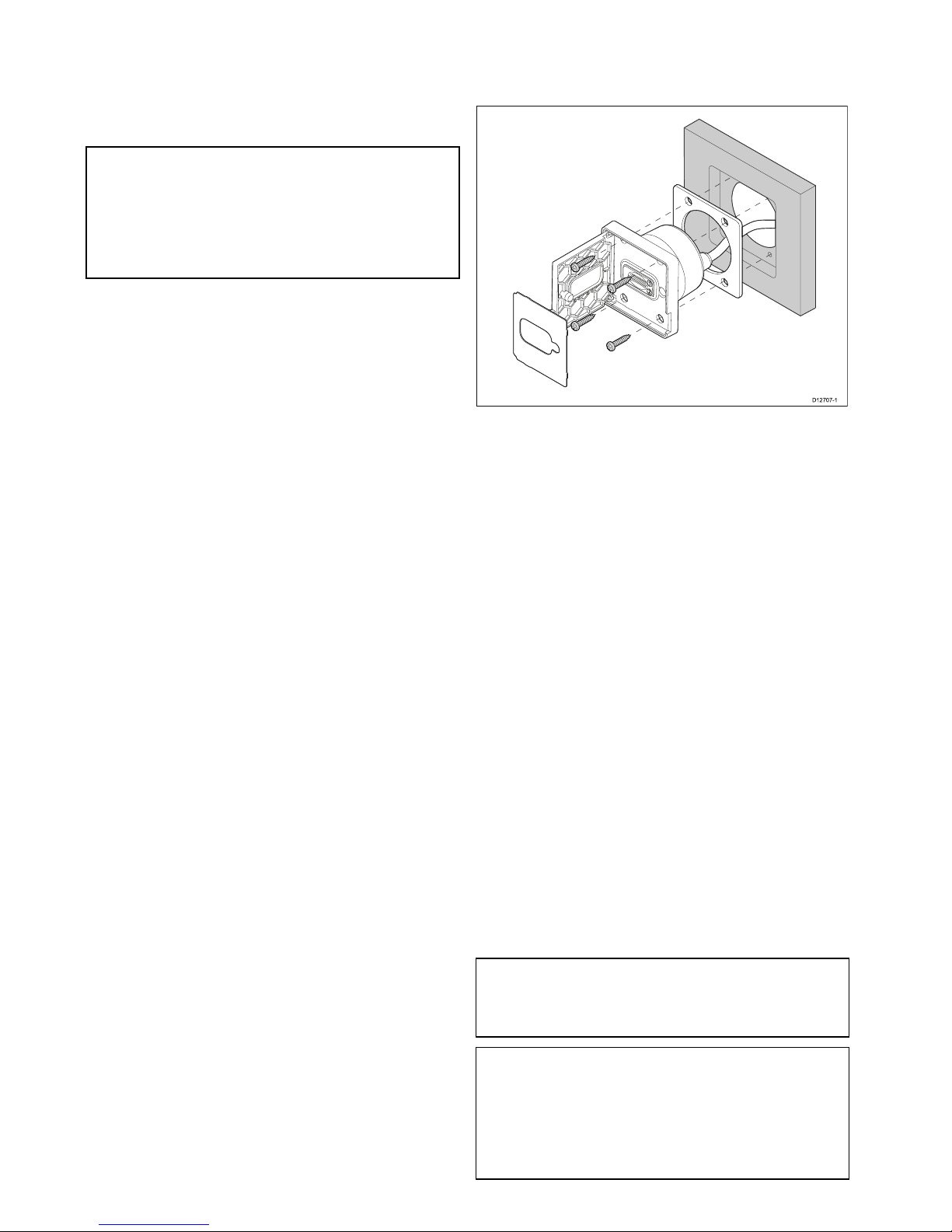
13.Usingasuitablesizedwrenchtightenthelock
nutagainstthewasherandthemountingbracket
tolockinposition.
Thelocknutshouldbetightenedsufcientlyto
securelyholdthedisplayinposition.Donot
overtighten.
Note:Thesuppliedgasketprovidesaseal
betweentheunitandasuitablyatandstiff
mountingsurfaceorbinnacle.Thegasketshould
beusedinallinstallations.Itmayalsobe
necessarytouseamarine-gradesealantifthe
mountingsurfaceorbinnacleisnotentirelyatand
stifforhasaroughsurfacenish.
5.4Flushmountingthecardreader
Forushmountingyoumustrebatethemounting
surfacetoaccommodatechartreaderhousing.
D12707-1
1.Checktheselectedlocationfortheunit.Aclear,
atareawithsuitableclearancebehindthepanel
isrequired.
2.Beforemodifyingthemountingsurface,refer
tothedimensionssuppliedinthisdocumentto
ensurethereisenoughspacefortheunitand
cable.
3.Fixthesuppliedmountingtemplatetothe
selectedlocation,usingmaskingorself-adhesive
tape.
4.Drill4holesasindicatedonthemounting
templatetoacceptthexings.
5.Usinga40mm(1.6in)holecutter,drilloutthe
cut-outareaidentiedonthemountingtemplate.
6.Followtherebatecut-outlineonthetemplateto
cutarebatearoundtheholewithadepthof8.5
mm(0.33in),toaccepttheunit.
7.Ensurethatthecardreadertsintotheremoved
areaandthenremoveroughedges.
8.Afxthesuppliedgasketontotherearofthecard
readerandpressrmlyontotheange.
9.Feedthecablethroughtheholeandconnectto
themultifunctiondisplay’scardreaderconnector.
10.Placethecardreaderintotherebateandsecure
usingthexingsprovided.
11.Insertthecardreaderlabeloverthetopofthe
cardreaderslotssothatthemountingscrew
locationsarecovered.
Note:Theappropriatetighteningtorqueanddrill
bitsizetousedependsonthethicknessofthe
mountingsurfaceandthetypeofmaterialitis
madefrom.
Note:Thesuppliedgasketprovidesaseal
betweentheunitandasuitablyatandstiff
mountingsurfaceorbinnacle.Thegasketshould
beusedinallinstallations.Itmayalsobe
necessarytouseamarine-gradesealantifthe
mountingsurfaceorbinnacleisnotentirelyatand
stifforhasaroughsurfacenish.
78
gSSeries

5.5Surfacemountingthedisplay
1.Checktheselectedlocationfortheunit.Aclear,
atareawithsuitableclearancebehindthepanel
isrequired.
2.Beforemodifyingthemountingsurface,refer
tothedimensionssuppliedinthisdocumentto
ensurethereisenoughspaceforthedisplayand
allcables.
3.Fixthesuppliedmountingtemplatetothe
selectedlocation,usingmaskingorself-adhesive
tape.
4.Usingasuitableholesaw(thesizeandposition
isindicatedonthetemplate),makeaholeineach
cornerofthecut-outarea.
5.Usingasuitablesaw,cutalongtheinsideedge
oftherearcasingcut-outlineindicatedonthe
template.
6.Ensurethattheunittsintotheremovedarea
andthenremoveanyroughedges.
D12696-1
7.Afxthesuppliedgasketontotherearofthe
displayandpressrmlyontotheange.
8.Connectthepower,dataandothercablestothe
unit.
9.Attachthesuppliedmountingbracketstothe
rearofthedisplayusingthesuppliedxings,as
showninthediagrambelow.Useonebracketfor
eachsideofthedisplay.
D12723-2
Note:Refertothe5.1Bracketmountinghole
locationssectionfordetailsofthelocationofthe
bracketmountingholesontherearofyourdisplay.
10.Securethedisplayusingtheprovidedmounting
xings(bolt,washer,locknutandfoot.In4
locations.
Dependingonthethicknessofthemounting
surfacethewasherandlocknutmaybelocated:
1.betweenthemountingbracketandmounting
feet(asshownin(1)and(2)below,or
2.afterthemountingbracketasshownin(3)
and(4)below.
1 2
3 4
D13043-1
11.Usingasuitableallenkey,tightenthebracket
mountingboltssothatthefeetaretightagainst
therearofthemountingsurface.
Mounting
79

12.Usingasuitablesizedwrenchtightenthelock
nutagainstthewasherandthemountingbracket
tolockinposition.
Thelocknutshouldbetightenedsufcientlyto
securelyholdthedisplayinposition.Donot
overtighten.
Note:Thesuppliedgasketprovidesaseal
betweentheunitandasuitablyatandstiff
mountingsurfaceorbinnacle.Thegasketshould
beusedinallinstallations.Itmayalsobe
necessarytouseamarine-gradesealantifthe
mountingsurfaceorbinnacleisnotentirelyatand
stifforhasaroughsurfacenish.
5.6Surfacemountingthecardreader
D12721-1
1.Checktheselectedlocationfortheunit.Aclear,
atareawithsuitableclearancebehindthepanel
isrequired.
2.Beforemodifyingthemountingsurface,refer
tothedimensionssuppliedinthisdocumentto
ensurethereisenoughspacefortheunitand
cable.
3.Fixthesuppliedmountingtemplatetothe
selectedlocation,usingmaskingorself-adhesive
tape.
4.Drill4holesasindicatedonthemounting
templatetoacceptthexings.
5.Usinga40mm(1.6in)holecutter,drilloutthe
cut-outareaidentiedonthemountingtemplate.
6.Ensurethatthecardreadertsintotheremoved
areaandthenremoveroughedges.
7.Afxthesuppliedgasketontotherearofthecard
readerandpressrmlyontotheange.
8.Feedthecablethroughtheholeandconnectto
themultifunctiondisplay’scardreaderconnector.
9.Secureusingthexingsprovided.
10.Insertthecardreaderlabeloverthetopofthe
cardreaderslotssothatthemountingscrew
locationsarecovered.
Note:Theappropriatetighteningtorqueanddrill
bitsizetousedependsonthethicknessofthe
mountingsurfaceandthetypeofmaterialitis
madefrom.
Note:Thesuppliedgasketprovidesaseal
betweentheunitandasuitablyatandstiff
mountingsurfaceorbinnacle.Thegasketshould
beusedinallinstallations.Itmayalsobe
necessarytouseamarine-gradesealantifthe
mountingsurfaceorbinnacleisnotentirelyatand
stifforhasaroughsurfacenish.
80
gSSeries

Chapter6:Gettingstarted
Chaptercontents
•6.1Switchingtheunitonandoffonpage82
•6.2Controlsonpage83
•6.3Homescreenoverview—T ouchonlydisplaysonpage85
•6.4Pagesonpage87
•6.5Applicationsonpage88
•6.6Splitscreencontrolsonpage89
•6.7Screenoverviewonpage90
•6.8Basictouchscreenoperationsonpage93
•6.9Multi-Touchgesturesonpage94
•6.10Initialsetupproceduresonpage94
•6.11Enablingautopilotcontrolonpage97
•6.12Engineidenticationonpage98
•6.13EnablingAISfunctionsonpage100
•6.14Sharedpreferencesonpage100
•6.15Systemsoftwareupdatesonpage101
•6.16Learningresourcesonpage102
Gettingstarted
81

6.1Switchingtheunitonandoff
Poweringthedisplayon
1.PressthePOWERbuttononthedisplay .
2.SelectAccepttoacknowledgethedisclaimer
message.
PuttingthedisplayintoStandby
1.PressandholdthePOWERbuttonuntilthe
countdownreacheszero.
IfthePOWERbuttonisreleasedbeforethe
countdownreacheszero,normaloperationis
resumed.
StandbymodeallowstheinternalSeaTalk
hs
networkhubandPoEfunctionsofthedisplay
toremainactivewhilstallotherfunctionsare
poweredoff.
RefertotheTechnicalspecicationfordetailson
powerconsumptionwheninStandbymode.
Note:T ocompletelypoweroffthedisplaysothatit
isnolongerconsumingpowerthedisplaymustbe
isolatedfromthepowersupplyviathedistribution
panelorbreaker.
PowerSavemode
InPowerSavemodeallfunctionsofthemultifunction
displayremainactive,buttheunitisplacedintoa
lowpowerstate.PowerSavemodeisautomatically
cancelledwhenanalarmeventoccurs.
Note:T oensureusersafetythePowerSave
featurewillnotbeavailableif:
•anyconnectedradarsareswitchedon
•themultifunctiondisplayisprovidingautopilot
controlinasystemwithoutadedicatedpilot
headandtheautopilotisengaged.
AttentionAgSSeriesMFDinPowerSavemode
willcontinuetoconsumesomepowerfromyour
vessel’sbatteries.Theunitcoulddrainyourbatteries
ifleftinPowerSavemodeforprolongedperiodsof
time.Whenswitchingoffthepowertoyourvessel,
ensurethattheunitisswitchedoffatthepower
distributionpanelorbreaker.Formoreinformation
ontheamountofpowerconsumedbytheunitin
PowerSavemode,refertoChapter31T echnical
specication.
EnablingPowerSavemode
ToenablePowerSavemodefollowthestepsbelow.
1.Ensureanyradarsconnectedtothesystemare
switchedoff.
2.PressthePOWERbutton.
Theshortcutsmenuisdisplayed.
3.SelectPowerSaveMode.
ThemultifunctiondisplaysisnowinPowerSave
mode.
4.YoucanwaketheunitfromPowerSavemode
atanytimebypressingthePowerbuttonorany
buttononaconnectedkeypad.
Note:PowerSavemodeisautomaticallycancelled
ifanalarmeventoccurs.
82
gSSeries

6.2Controls
D12701-1
1 2 3
DescriptionFunctions
1Touch-
screen
Touchthescreentooperatefunctions,
includingallmenuoperations.
2Power•Pressoncetoswitchtheuniton.
•Whenpoweredon,pressthePower
buttonagainopentheShortcutspage.
•Whenpoweredon,pressandholdto
putthedisplayintoStandbymode.
•Ifanintegratedpilotisengaged,press
andholdtoputtheautopilotinto
STANDBYmode.
3
Card
reader
Openthecarddoortoinsertorremove
aMicroSDcard.Thereare2cardslots
(labelled1and2),usedforelectronic
chartsandarchivingwaypoint,route,track
andsettingsdata.
Keypadcontrols
Connectingthekeypadallowsyoutocontrolyour
multifunctiondisplayremotely.
D12711-1
1
3
5
7
9
2
4
6
8
10
1011 7
8
3 4
9 5 6 1 2
1.Home—presstoreturntotheHomescreen.
2.Menu—accessesmenus.Pressagaintoclose
menus.
3.UniControl—providesarotarycontrolanda
joystickwithanOKpushbuttonforusingmenus
andapplications.
4.Back—presstoreturntoapreviousmenuor
dialoglevel.
5.RangeOut—presstorangeout.
6.RangeIn—presstorangein.
7.SwitchActive—presstoswitchtheactive
pane,ortoswitchtheactivemultifunctiondisplay
(inmultipledisplaysystems).
8.WPT/MOB—pressandreleasetoaccess
thewaypointoptions.Pressagaintoplace
awaypoint.PressandholdtoplaceaMan
Overboard(MOB)markeratyourcurrent
position.
9.Standby(Auto)—presstodisengage
integratedautopilot,pressandholdtoactivate
Automodeonintegratedautopilot.
10.Power—seetablebelow:
Conguration
Display
State
Momentary
press
Pressand
hold
Off/Standby*Poweron
—
1
Multifunction
display
OnOpen
shortcuts
page
Poweroff
/putinto
Standby
Alldisplays
Offorin
Standby
*Poweron
alldisplays
—
Alldisplays
On
Open
shortcuts
pageon
activedisplay
Powerdown
alldisplays
Multiple
multifunction
displays
1Display
Onand1
displayOff
orinStandby
Open
shortcuts
pageon
activedisplay
Powerdown
activedisplay
Note:*OnlyapplicabletogSSeriesdisplays.
aSeries,cSeriesandeSeriesdisplayscannot
bepoweredonusingthekeypad.
Note:Inamultipledisplayconguration,
wheredisplaysareindifferentstates,displays
thatareturnedoffcanonlybeturnedonusing
thePowerbuttononthedisplay.
11.JoystickUpdirection.
Gettingstarted
83

UniControl
Non-touch,HybridTouchandtheremotekeypad
includeaUniControlwhichconsistsofRotary,
Joystickandapushbuttoncontrol.
D1218 0-1
1
2
3
1.Rotary—usethistoselectmenuitems,move
theon-screencursor,andadjusttherangeinthe
chartandradarapplications.
2.Joystick—usethistomovethecursorposition
inapplications,panup,down,leftandrightinthe
chart,weatherandshnderapplicationsorto
cyclethroughdatapagesinthedataapplication.
3.OKbutton—pushtheendofthejoystickto
conrmaselectionorentry.
Touchicons
Touchscreenmultifunctiondisplayscanuse
theBACKandCLOSEiconstomovebetween
thedifferentlevelsofmenusavailableineach
application.
Back—gobackonelevel(sameeffectaspressing
theBACKbutton).
Close—closeallopenmenus(sameeffectas
pressingtheMENUbutton).
Usingthecursor
Thecursorisusedtomovearoundthescreen.
D7366_3
Thecursorappearsonthescreenasawhite
cross.
D7368_2
Ifthecursorhasnotbeenmovedforashort
periodoftime,itchangestoacirclewithacross
init,tomakeiteasiertolocateonthescreen.
D7369-2
WPT
Thecursoriscontext-sensitive.Whenitis
placedoveranobjectsuchasawaypointor
chartfeature,itchangescolorandalabel
orinformationassociatedwiththeobjectis
displayed.
Listofcursorlabels
LabelFeatureApplication
A/B
Rulerline
Chart
AISAIStargetChart
COGCourseOver
Groundvector
Chart
CTRCenterofradar
Radar
FLT
FloatingEBL/VRM
Radar
GRDGuardzone
Radar
HDG
Headingvector
Chart
MARPAMARPAtargetRadar
MOBManOverBoard
marker
Chart,Radar
POS
Vessel'sposition
Chart
RTERouteleg
Chart
SHMShip'sHeading
Marker
Radar
TIDETideindicator
Chart
TRACK
Trackline
Chart
VRM/EBL
VRMandEBL,1
or2
Radar
WINDWindindicator
Chart
WPTWaypoint
Chart,Radar
84
gSSeries

6.3Homescreenoverview—Touch
onlydisplays
TheHomescreenprovidesacentralpointofaccess
foryourdisplay'sapplications,dataandsettings.
•TheHomescreenprovidesquickaccesstoyour
data(waypoints,routes,tracks,imagesand
videos)andbackupsettings.
•TheHomescreenconsistsofanumberof
Homescreenpages.Swipethescreenleftorright
withyourngertoscrollthroughtheavailable
Homescreenpages.
•EachHomescreenpageconsistsofanumberof
icons.Applicationsarestartedbyselectingthe
relevanticon.
D12580-3
1 2
3
4
5 6
Screen
itemDescription
1Waypoint—selecttheicontoaccessthe
waypointlist.Selectandholdontheiconto
placeaManOverboard(MOB)markeratyour
vessel’scurrentposition.
2MyData—thisiconenablesyoutocentrally
manageyourdataincludingroute,track,and
waypointlists.Youcanalsoaccesssaved
picturesandvideosandbackupsettings.
3
Customize—selectthisicontocongure
applicationpagesanddisplaypreferences.
4
Set-up—selectthisicontoaccessthesystem
set-upmenus.
5
Icon—eachiconrepresentsanapplication
page.Apagecandisplaymultipleapplications
simultaneously.
6
Statusbar—thestatusiconsconrmthe
statusofexternally-connectedequipment,
includingGPS,AIS,radar,sonarandautopilot
units.
Accessingthehomescreen
Thehomescreencanbeaccessedfromany
application.
Toaccessthehomescreenfollowthestepsbelow:
1.Selectthehomescreeniconon-screen.
Databarstatussymbols
Thestatussymbolsonthedatabarconrmwhether
theappropriateconnectionstoyoursystemhave
beenmade.
Thesymbolsshowthestatusforthefollowing:
•Radarscanner.
•AISreceiver/transceiver.
•Sonarmodule.
•GPSreceiver.
•Autopilot.
Autopilotstatussymbols
Theautopilotstatusisindicatedinthedatabar.
SymbolDescription
AutopilotisinStandbymode.
AutopilotisinTrackmode.
AutopilotisinAutomode.
Noautopilotdetected.
Autopilotalarmactive.
Dodgemodeisactive.
Fishmodeisactive.
Autopilotcalibration.
Powersteeringactive.
WindVanemodeisactive.
Gettingstarted
85

Radarscannerstatussymbols
Theradarscannerpowermodestatusisindicated
inthedatabar.
Symbol
Radar
power
modeDescription
Transmit(TX)
Rotatingicon,signifyingthatthe
scannerisonandtransmitting.
WhenSCANNERissettoON,
selectthismodetoactivatethe
scanner.Thisistheusualmodeof
operation.
Standby
(STBY)
Staticicon,indicatingthatthe
scannerisonbutnottransmitting,
andtheantennaisnotrotating.
Thescannerdoesnottransmitand
theradardataisremovedfromthe
screen.Thisisapower-savemode
usedwhentheradarisnotneeded
forshorttimeperiods.When
youreturntotransmitmode,the
magnetrondoesnotneedtowarm
upagain.Thisisthedefaultmode.
OffScannerpoweredoffwhenradar
notrequired,butdisplayisinuse
forotherapplications,suchasthe
chart.Whenselected,thesystem
countsdown.Duringthistimeyou
cannotre-powerthescanner.
Timed
Transmit
Scannerswitchesbetween
on/transmitting,andstandbymode.
Scannergoesintopowersave
modewhenconstantuseofradar
isnotrequired.
AISstatussymbols
AISstatusisindicatedbyasymbolinthedatabar.
SymbolDescription
AISunitisswitchedonandoperating.
AIScurrentlyunavailable.
AISunitisswitchedoff,ornot
connected.
AISunitisinSilentMode.
AISunitisinSilentMode,withactive
alarms.
SymbolDescription
AISunitisconnectedandswitched
on,buthasactivealarms.
AISunitisconnectedandswitched
on,butthedangerousandlostalarm
isdisabled.
Sonarstatussymbols
Thesonarstatusisindicatedinthedatabar.
SymbolDescription
Symbolanimated:thesonar
moduleisconnectedand
transmitting.
Symbolstatic:thesonar
moduleisconnectedbutnot
transmitting.
Symbolgreyed-out:thesonar
moduleisnotconnected,or
isnotdetected.
GPSstatussymbols
TheGPSreceiverstatusisindicatedinthedatabar.
SymbolDescription
AGPSreceiverisconnected
andhasobtainedax.
AGPSreceiverisnot
connected,orcannotobtain
ax.
86
gSSeries

6.4Pages
Pagesaremadeupof1to4panesthatareused
todisplayapplicationsonyourmultifunctiondisplay
(MFD).
Pagesareaccessedusingtheiconsonthe
Homescreen.
•Youcancreateupto2applicationpanesperpage
usinganMFDthathasascreensizeof7inches
orless.
•Youcancreateupto4applicationpanesperpage
usinganMFDthathasascreensizeofgreater
than7inches.
•MFDswithascreensizeof7inchesorlesscan
viewpageswithmorethan2applicationpanes
butonlyiftheyaresharingtheHomescreenofan
MFDwhichiscapableofcreatingthosepages.
Pagescanbecustomized,enablingyoutogroup
yourapplicationsintodifferentpages,eachdesigned
foraspecicpurpose.Forexample,youcould
haveapagethatincludesthechartandshnder
applications,suitableforshing,andanotherpage
thatincludesthechartanddataapplications,which
wouldbesuitableforgeneralsailing.
Iconforapagefeaturingasingle
application.
Iconforapagefeaturingmultiple
applications.
Youcanalsodenethelayoutforeachpage,which
determineshowtheapplicationsarearrangedon
thescreen.
SettingthePower-uppage
Youcansetupyourmultifunctiondisplaytoshowa
pageinsteadoftheHomescreenatpowerup.
FormtheHomescreen:
1.SelectCustomize.
2.SelectDisplayPreferences.
3.SelectStartingpage.
Alistofoptionsisdisplayed
•Homescreen—Homescreenisdisplayedafter
power-up.
•Lastpage—Thepagelastviewedisdisplayed
afterpower-up
•Choosepage—Thepageyouselectwillbe
displayedafterpower-up
4.IfselectingChoosepagetheHomescreenis
displayed.
5.Selecttheiconforthepageyouwantdisplayed
whenthedisplayisturnedon.
Thestartingpagesettingappliestoeachindividual
displayandisnotautomaticallysharedonnetworked
displays.
Changinganexistingpageonthe
homescreen
Withthehomescreendisplayed:
1.SelectCustomize.
2.SelectHomescreen.
3.SelectEditPage.
4.Selectthepageiconthatyouwanttochange.
TheCustomizemenuoptionsaredisplayed.
5.Selecttheappropriatepagelayout(forexample,
“Splitscreen”).
6.Selecttheapplication(s)youwanttodisplayon
thepage,eitherbyselectingtherelevantmenu
itemordraggingitovertothedisplayedpage.
7.SelectFinish.
TheRenamePagedialogisdisplayed.
8.Usetheon-screenkeyboardtonamethepage,
thenselectSave.
Changinganemptypage
Withthehomescreendisplayed:
1.SelectCustomize.
2.SelectHomescreen.
3.SelectEditPage.
4.Selectanemptypageicon(labelled“Customize”).
TheCustomizemenuoptionsaredisplayed.
5.Selecttheappropriatepagelayout(forexample,
“Splitscreen”).
6.Selecttheapplication(s)youwanttodisplayon
thepage,eitherbyselectingtherelevantmenu
itemordraggingitovertothedisplayedpage.
7.SelectFinish.
TheRenamePagedialogisdisplayed.
8.Usetheon-screenkeyboardtonamethepage,
thenselectSave.
Movingapageonthehomescreen
Withthehomescreendisplayed:
1.SelecttheCustomizeicon.
2.SelectHomescreen.
3.SelectSwapPage.
Gettingstarted
87

4.Selectthepageiconthatyouwanttomove.
5.Selectthepageiconthatyouwanttoswap
positionswith.
Thepageiconismovedtothenewposition.
Renamingapageonthehomescreen
Withthehomescreendisplayed:
1.SelecttheCustomizeicon.
2.SelectHomescreen.
3.SelectRenamePage.
4.Selectthepagethatyouwanttorename.
Theon-screenkeyboardisdisplayed.
5.Usingtheon-screenkeyboard,enterthenew
nameforthepage.
6.SelectSA VE.
Deletingapagefromthehomescreen
Withthehomescreendisplayed:
1.SelecttheCustomizeicon.
2.SelectHomescreen.
3.SelectDeletePage.
4.Selectthepagethatyouwanttodelete.
Thepageisdeleted.
Resettingthehomescreentodefaultsettings
Withthehomescreendisplayed:
1.SelecttheCustomizeicon.
2.SelectHomescreen.
3.SelectReset.
Awarningmessageisdisplayedaskingfor
conrmation.
4.SelectYestoresetthehomescreentothedefault
rangeofpages,orNotocanceltheoperation.
6.5Applications
Chartapplication—providesa2Dor
3Dgraphicalviewofyourchartstohelp
younavigate.Waypoint,route,and
trackfunctionsenableyoutonavigate
toaspeciclocation,buildandnavigate
routes,orrecordwhereyou'vebeen.
Chartcardsprovidehigherlevelsof
detailand3Dviews.
Fishnderapplication—with
atransducerandasonarvariant
multifunctiondisplayorcompatible
SonarModule,youcanusethe
shnderapplicationtohelpyou
accuratelydistinguishbetweendifferent
sizesofsh,bottomstructure,and
underwaterobstacles.Youcanalso
viewseadepthandtemperaturedata
andmarkpointsofinterestsuchas
shingspotsorwrecks.
Radarapplication—withasuitable
radarscanner,youcanusethe
radarapplicationtotracktargetsand
measuredistancesandbearings.A
numberofautomaticgainpresetsand
colormodesareprovidedtohelpyou
getthebestperformancefromyour
radarscanner.
Dataapplication—viewsystemand
instrumentdataonyourmultifunction
display,forarangeofcompatible
instruments.Usethejoystickor
touchscreentoscrollthroughthe
availabledatapages.
Weatherapplication—(North
Americaonly).Withasuitableweather
receiverconnectedtoyoursystem,the
weatherapplicationoverlayshistorical,
live,andforecastedweathergraphics
onaworldmap.
Thermalcamapplication—view
andcontrolathermalcamerausinga
compatiblemultifunctiondisplay.
Note:Thethermalcamera
applicationisnotavailableona6x
anda7xvariantMFDs.
Cameraapplication—viewavideo
orcamerasourceonyourmultifunction
display.
DocViewer—viewpdfdocuments
storedonaMicroSDcard.
88
gSSeries

FUSIONLinkapplication—link
toandcontrolacompatibleFusion
entertainmentsystemfromyour
multifunctiondisplay .
SiriusAudioapplication—control
Siriusradiofromyourmultifunction
display.
UserManual—OpenstheEnglish
versionoftheproductusermanual
storedonthedisplay.T oopen
translatedusermanualsstoredon
memorycardusetheDocViewer.
6.6Splitscreencontrols
Whenviewingapagewithmorethan1application
displayedyoucanswitchapplicationsfromthe
splitscreenviewtofullscreenview.
Example1—Splitscreenpage
Example2—Fishnderapplicationexpanded
toFullscreen
Selectingtheactivewindow
Whenviewingasplitscreenpageyoucanselectthe
activeapplicationandviewitfullscreenbyfollowing
thestepsbelow.
Withapagefeaturingmultipleapplicationsdisplayed:
1.Touchanywhereinsidetheapplicationyouwant
tomakeactive.
Aborderappearsaroundtheapplication,
indicatingthatitisactive.
2.SelectMenu.
3.SelectFullscreentoviewtheactiveapplication
infullscreen,or
4.SelectSplitscreentoreturntothesplitscreen
view.
Selectingtheactivewindowusing
Non-touchcontrols
Whenviewingasplitscreenpageyoucanselectthe
activeapplicationandviewitfullscreenusingthe
MFD’sphysicalbuttonsoraremotekeypad.
Withapagefeaturingmultipleapplicationsdisplayed:
1.Pressthe
SwitchActivebutton.
Theactivepanepopupisdisplayed:
2.PresstheSwitchActivePanebuttonorusethe
Rotarycontroltocycletheactiveapplication.
Gettingstarted
89

3.UsetheRangeinorRangeoutcontrolsto
switchtheactiveapplicationbetweensplitscreen
andfullscreenviews.
Switchingtheactivepaneordisplayusing
thekeypad
TheSwitchActivebuttonisusedtoswitchtheactive
paneonamultiapplicationpageand/ortoswitch
theactivedisplay.
Withmultipledisplaysconnectedand/oramultiple
applicationpagedisplayed:
Cyclesequence
4
1 2 3 5
D12703-1
1.PresstheSwitchActivebuttontoenterswitch
mode.
2.UsetheRotaryControltocyclethroughthe
availablepanesand/ordisplays.
Thekeypadwillcyclethroughdisplaysinthe
orderinwhichtheywerepaired.Onmulti
applicationpagestheRangebuttonscanbeused
toswitchtheactiveapplicationbetweenfulland
splitscreen.
3.PresstheBackbuttonortheSwitchActive
buttontoexitswitchmode.
6.7Screenoverview
7
6
1
2 3
4
5
ScreenitemDescription
1Home—selecttheHomeicontoaccessthe
homescreen.
2
Databar—providesinformationaboutyour
vesselanditsenvironment.Theposition
andtypeofinformationinthedatabarcan
becustomizedfromtheHomescreen>
Customize>DatabarSet-upmenu,if
required.
3
Menu—themenuoptionsarespecictothe
applicationthatyouarecurrentlyusing.
4Pop-upmenu—menuoptionsaredisplayed
whentheMenuisselected.
5
Pop-upmessages—alertyoutoasituation
(suchasanalarm),orunavailablefunction.
Pop-upmessagesmayrequirearesponse
fromyou—forexample,selectOKtosilence
alarms.
6Dialogs—enabledatatobeselected,edited
orentered.Useinmanycommonfunctions
—forexample,editingawaypoint.
7
Contextmenu—providesinformationand
optionsspecictoeachapplication.
8
Statusbar—providesinformationspecic
toeachapplication.Thisinformationcannot
beeditedormoved.
Menus
Menusenableyouconguresettingsand
preferences.
Menusareusedinthe:
•Homescreen—tocongureyourmultifunction
displayandexternally-connectedequipment.
•Applications—tocongurethesettingsforthat
particularapplication.
90
gSSeries

D12281- 4
3
4
5
1 2
Screen
itemDescription
1
Back—Ondisplayswithatouchscreenyoucan
presstheonscreen<<(back)icontogobackto
apreviousmenu.Onnon-touchscreendisplays
orHybridTouchdisplaysusetheBackbutton.
2
Close—Ondisplayswithatouchscreenyou
canpresstheonscreenX(close)icontogo
backtoapreviousmenu.Onnon-touchscreen
displaysorHybridTouchdisplaysusetheBack
buttontobackoutofthemenustructure.
3
Selectedmenuoption—themenuoption
currentlyselectedwillbehighlighted.
4
Scrollbar—indicatesthatfurthermenu
itemsareavailablebyscrollingthemenu.On
displayswithatouchscreentoscrollthrough
theavailablemenuitems,pressandholdyour
ngeronthemenuanddragitupordown.
Onnon-touchscreendisplaysorHybridTouch
displaysusetheRotarycontrol.
5
On/Offswitch—Ondisplayswitha
touchscreenyoucanselectonscreenmenu
itemstoswitchfeaturesOnorOfftoenable
ordisablethefunction.Onnon-touchscreen
displaysorHybridT ouchdisplaysusetheOK
buttontoswitchthefunctionOnorOff.
Dialogs
Dialogsarefullscreenmenusthatenableyouto
managedataitemssuchaswaypointsandroutes.
D12277-2
1 4
5
2 3
ScreenitemDescription
1Back
•Displayswithatouchscreen—Selectthe
onscreenBackicontogobacktothe
previousmenu.
•Non–touchscreenorHybridTouchdisplays
—UsetheBackbuttontogobacktothe
previousmenu.
2
Functionicons—Somedialogsinclude
iconswhichcanbeselectedtoaccess
additionalfunctions.Forexample,inthe
WaypointListdialog,theSortbyiconcan
beusedtochangehowthewaypointslistis
sorted.
3
Menu/Listitem
•Displayswithatouchscreen—
Momentarilytouchinganitemautomatically
selectstheitemanddisplaystheitem
optionsmenu.
•Non–touchscreenorHybridTouchdisplays
—UsetheRotarycontroltohighlightan
item,andtheOkbuttontoselectitand
displaytheitemoptionsmenu.
4
Close
•Displayswithatouchscreen—Selectthe
onscreenCloseicontoclosethedialog.
•Non–touchscreenorHybridTouchdisplays
—UsetheBackbuttontoclosethedialog.
5
Scrollbar
•Displayswithatouchscreen—Toscroll
throughtheavailableitems,pressand
holdyourngeronthescrollbaranddrag
itupordown.
•Non–touchscreenorHybridTouchdisplays
—T oscrollthroughtheavailablemenu
items,usetheRotarycontrol.
Shortcutspage
Anumberofusefulfunctionscanbeaccessedfrom
theShortcutspage.
D13004-1
1
3
5
7
8
4
2
6
Gettingstarted
91

1Decreasedisplaybrightness
2Increasedisplaybrightness
3
Powerup/PowerdownRadar
4
Radarstandby/Radartransmit
5
Autopilotstandby(duringactivenavigation)
6Displaypilotcontroldialog
7
PowerSavemode
8
Screenshot/Screencapture
Editdialogs
Editdialogsenableyoutoeditthedetailsofdata
itemsstoredonyourmultifunctiondisplay,suchas
waypoints,routes,andtracks.
Selectingatextelddisplaystheonscreenkeyboard,
whichcanbeusedtoeditthedetails.
Editinginformationindialogs
Withthedialogdisplayed:
1.Selecttheeldyouwanttoedit.
Theonscreenkeyboardisdisplayed:
2.Usetheonscreenkeyboardtomakethechanges.
3.SelectSAVEtosavethechanges.
Enteringspecialoraccentedcharacters
Withtheonscreenkeyboarddisplayed:
1.Selecttheonscreenkeyboard'sàèòkey.
2.Selectthecharacteryouwanttoaccent.
Theavailableaccentedcharactersaredisplayed
abovethetextentryeld.
3.Forcharactersthathavemultipleavailable
accents,usethecharacterkeytotogglebetween
them.
4.Selecttheàèòkeytoenterthecharacter.
Numericmenuitems
Numericmenuitemsdisplaynumericdataand
enablesyoutoeitherselectapredenedvalueorto
increaseanddecreasethevalueasrequired.
Editingnumericalsettings
Toeditnumericalvaluesyoucanuseeitherthe
onscreennumericadjustcontrol,onscreennumeric
keypadortheRotaryControlonanon-touchor
HybridTouchdisplaytoincreaseordecreasenumeric
values.
D12567-2
1 2 3 4
1.Selectthenumericdataeldyouwanttoedit.
Thenumericadjustcontrolisdisplayed.
2.Adjustthesettingtotherequiredvalueusing:
i.TheRotarycontrol—Non-touchscreenor
HybridTouchdisplays,or
ii.TheonscreenUpandDownarrows—
Touchscreendisplays.
3.Toaccesstheon-screennumerickeypad:
•Touchoperation—Selecttheonscreenkeypad
iconfromthenumericadjustcontrol.
•Non-Touchoperation—PressandholdtheOk
button.
Theonscreennumerickeypadisdisplayed.
4.Entertherequiredvalue.
5.SelectOktoexitthenumerickeypadandreturn
tothemenu.
92
gSSeries

Usingsliderbarcontrols
Sliderbarcontrolsprovideagraphicalrepresentation
ofnumericdataandenablesyoutoquicklychange
settingvalues.
1
2
3
D1257 0-1
Item
Description
Non—Touch
operationTouchoperation
1
Current
value
N/AN/A
2
Slider
control
UsetheRotary
controltoadjust
value
SlidethesliderUp
orDowntoadjust
value.
3Auto
PressOkbutton
toswitchbetween
Autoandmanual
adjustment.
Selecttoswitch
betweenAuto
andmanual
adjustment.
Usingcontroldialogs
Controldialogsenableyoutocontrolexternally
connectedequipment,suchasanautopilotunit.
Thefollowingdiagramshowsthemainfeaturesof
atypicalcontroldialog:
D12279-2
1
3
2
ScreenitemDescription
1
Status—providesstatusinformationforthe
connectedequipment.Forexample,thePilot
Controldialogdisplaysthelockedheading
andcurrentnavigationmodeforaconnected
autopilotunit.
2
Controlicons—providedirectcontrolof
theconnectedequipment.Forexample,the
PilotControldialogStandbyandTrackicons
enableyoutoinstructaconnectedautopilot
unittoperformspecicfunctions.
3
Close—Closesthecontroldialog.
6.8Basictouchscreenoperations
Placingandmovingthecursorusing
touch
Toplaceormovethecursoraroundthescreenon
atouchscreenmultifunctiondisplayfollowthesteps
below.
1.Touchthescreenatanypositiononthescreento
placethecursorthere.
Touchscreenlock
OnamultifunctiondisplaywithHybridT ouchyoucan
lockthetouchscreentopreventaccidentaluse.
Forexample,lockingthetouchscreenisparticularly
usefulinroughwaterorweatherconditions.
Thetouchscreencanbelockedandunlockedfrom
thehomescreen.Thetouchscreencanonlybe
unlockedusingphysicalbuttons.
Lockingthetouchscreen-touchonlydisplays
Whenatouchonlydisplayispairedwithanoptional
remotekeypadthetouchscreencanbelocked.
FromtheHomescreen:
1.SelecttheSet-upicon.
2.SelectTouch-LocksothatOnishighlighted.
Thetouchscreenisnowlocked.
Unlockingthetouchscreen-touchonlydisplays
Tounlockthetouchscreenofatouchonlydisplay
whenpairedwitharemotekeypadfollowthesteps
below.
FromtheHomescreen:
1.SelecttheSet-upicon.
2.SelectTouch-LocksothatOffishighlighted.
Thetouchscreenisnowunlocked.
Gettingstarted
93

6.9Multi-Touchgestures
RaymarineaSeriesandgSSeriesmultifunction
displayssupportmulti-touch.
Multi-touchmeansthatthedisplayiscapableof
recognizingmultiplesimultaneoustouchinputs.
Thismeansthatyoucanuse2ormorengerson
thescreenatthesametimetoperformmulti-touch
gestures.
PinchtoZoom
Thepinchtozoomgesturescanbeperformedon
multifunctiondisplaysthatsupportmulti-touch.
Pinchtozoomconsistsof2actions:
•Move2ngersaparttozoomin.
•Move2ngerstogethertozoomout.
0
0
0
0
0
0
0
0
D12920-2
PinchtoZoomcanbeusedinthefollowing
applications:
•Chartapplication.
•Weatherapplication.
6.10Initialsetupprocedures
Onceyourdisplayhasbeeninstalledand
commissioned,Raymarinerecommendsthatyou
performaninitialsetupprocedure.
Startupwizard
Whenyoupower-upthedisplayforthersttimeor
afterasystemresetaStartupWizardisdisplayed.
Thewizardguidesyouthroughthefollowingbasic
congurationsettings:
1.Language
2.Boattype
3.CongureUnits(Unitsofmeasure)
4.BoatDetails
•MinimumSafeDepth
•Numberofengines
•Totalfuelcapacity(TFC)
•Numberoffueltanks
•Numberofbatteries
Note:Thesesettingscanalsobesetatanytime
usingthemenusaccessiblefromHomescreen
>Customize.
Additionalsettings
InadditiontothesettingscoveredbytheWizard,
itisalsorecommendedthatthefollowinginitialset
uptasksarecompleted:
•Setyourdateandtimepreferences.
•Adjustthedisplaybrightness(andsetupashared
brightnessschemeifappropriate).
•Designatethedatamaster.
•SelecttheGPSdatasource.
•Familiarizeyourselfwiththeproductusing
SimulatorMode.
Adjustingthedisplaybrightness
94
gSSeries

1.PressthePOWERbuttononce.
TheShortcutsmenuisdisplayed.
2.Adjustthebrightnesstotherequiredlevelusing
theon-screenbrightnesssliderbarcontrol,or
3.TouchtheSunicontoincreasethebrightness
levelortheMoonicontodecreasethebrightness
level.
Note:Thebrightnesslevelcanalsobeincreased
bypressingthePowerbuttonmultipletimes.
Adjustingthedisplaybrightness
1.PressthePOWERbuttononce.
TheShortcutsmenuisdisplayed.
2.Adjustthebrightnesstotherequiredlevelusing
theRotarycontrol.
Note:Thebrightnesslevelcanalsobeincreased
bypressingthePowerbuttonmultipletimes.
Minimumsafevesseldepth
AspartoftheInitialstartupwizardtheMinimum
SafeDepthvaluecanbeset.
MinimumSafeDepthcanbeestablishedbyadding
together:
•MaximumVesselDraft(i.e.thedistancefromthe
waterlinetothelowestpointofavessel’skeel.)
•SafetyMargin(anadequateclearancebelowthe
keeltoallowfordraftvariationandchangesin
waterorbottomconditions.)
i.e.:MinimumSafeDepth=MaximumVesselDraft
+SafetyMargin.
D13159-1
2
4
1
3
1.Waterline
2.MaximumVesselDraft
3.SafetyMargin
4.MinimumSafeDepth
Important:Theinformationbelowisprovided
forguidanceonlyandisnotexhaustive.Some
inuencingfactorscanbeuniquetocertainvessels
and/orareasofwaterandmaynotbelisted
below.Y oushouldensureyouaccountforALL
factorsthatapplytoyourcurrentsituationwhen
makingcalculations.
Someofthefactorsthatcaninuencehowmucha
vesseldrawsareshownbelow:
•Vesseldisplacement(weight)—Avessel’sdraft
willincreasewhenitisfullyladenwhencompared
withitsunladendisplacement.
•Watertype—Avessel’sdraftwillincreaseby
approximately2%to3%infreshwatercompared
toseawater.
Someofthefactorsthatshouldbetakenintoaccount
whencalculatingaSafetyMarginare:
•Vesselmaneuveringcharacteristics—A
vessel’sdraftincreasesduetosquat,trim,roll,
pitchandheave.
•Chartaccuracy—Theelectronicchartdepth
maynotbeaccurateorthetruedepthmayhave
changedsincethelastsurvey.
•Weatherconditions—Highairpressure,and
prevailingwindstrengthanddirectioncanaffect
waveheight.
Warning:MinimumSafeDepth
TheMinimumSafeDepthsettingis
usedduringAutoroutingtorestrictthe
createdroutefromenteringwaterthatis
toshallowforthevessel.
Bottomdepthistakenfromcompatible
electronicnavigationalchartsand
MinimumSafeDepthisauser
calculation.Asbothofthesefactors
areoutsideofRaymarine’scontrol,
Raymarinewillnotbeheldliableforany
damage,physicalorotherwise,resulting
fromtheuseoftheAutoroutingfeature
ortheMinimumSafeDepthsetting.
SettingthevesselMinimumSafeDepth
Followthestepsbelowtoenteryourvessel’s
MinimumSafeDepth.
FromtheHomescreen:
1.SelectCustomize.
2.SelectBoatDetails.
3.SelectMin.SafeDepth.
4.EnteryourcalculatedMinimumSafeDepth.
Settingtimeanddatepreferences
Withthehomescreendisplayed:
1.SelectCustomize.
2.SelectTimeandDateSet-up.
3.UsetheDateFormat,TimeFormat,andLocal
Time:UTCmenuitemstosetyourtimeanddate
preferences.
Datamaster
Anysystemcontainingmorethanonenetworked
multifunctiondisplaymusthaveadesignateddata
master.
Thedatamasteristhedisplaywhichservesasa
primarysourceofdataforalldisplays,italsohandles
allexternalsourcesofinformation.Forexample
thedisplaysmayrequireheadinginformationfrom
theautopilotandGPSsystems,usuallyreceived
throughaSeaT alk
ng
orNMEAconnection.Thedata
masteristhedisplaytowhichtheSeaT alk,NMEA
andanyotherdataconnectionsaremade,itthen
bridgesthedatatotheSeaT alk
hs
networkandany
compatiblerepeatdisplays.Informationsharedby
thedatamasterincludes:
•Cartography
Gettingstarted
95

•Routesandwaypoints
•Radar
•Sonar
•Datareceivedfromtheautopilot,instruments,the
engineandotherexternalsources.
Yoursystemmaybewiredforredundancywithdata
connectionsmadetorepeatdisplays.Howeverthese
connectionswillonlybecomeactiveintheeventofa
faultand/orreassignmentofthedatamaster.
Inanautopilotsystemwhichdoesnotcontaina
dedicatedpilotcontrolheadtheDatamasteralso
actsasthecontrolfortheautopilot.
Designatingthedatamaster
Forsystemswith2ormoredisplaysthefollowing
taskmustbeperformedonthemultifunctiondisplay
thatyouwanttodesignateasthedatamaster.
Withthehomescreendisplayed:
1.SelectSet-up.
2.SelectMaintenance.
3.SelectDataMaster.
4.Selectthedisplaythatyouwanttodesignateas
thedatamaster.
Simulatormode
TheSimulatormodeenablesyoutopractice
operatingyourdisplaywithoutdatafromaGPS
antenna,radarscanner,AISunit,orshnder.
Thesimulatormodeisswitchedon/offinthe
SystemSetupMenu.
Note:RaymarinerecommendsthatyoudoNOT
usethesimulatormodewhilstnavigating.
Note:ThesimulatorwillNOTdisplayanyreal
data,includinganysafetymessages(suchas
thosereceivedfromAISunits).
Note:Anysystemsettingsmadewhilstin
SimulatormodeareNOTtransmittedtoother
equipment.
Enablinganddisablingsimulatormode
Youcanenableanddisablesimulatormodeby
followingthestepsbelow.
Withthehomescreendisplayed:
1.SelectSet-Up.
2.SelectSystemSettings.
3.SelectSimulator:.
4.SelectOntoturnsimulatormodeon,or
5.SelectOfftoturnsimulatormodeoff.
Note:TheDemomovieoptionisforretail
demonstrationpurposesonly.
Disablingandenablingtheauxiliaryalarm
Ifthereismorethanonealarmtted(e.g.auxiliary
alarmandremotekeypad)thentheauxiliaryalarm
canbeenabledordisabled.
Fromthehomescreen:
1.SelectSet-up.
2.SelectRemoteDevices.
3.SelectAuxiliaryAlarm.
4.SelectAuxiliaryAlarm.
SelectingAuxiliaryAlarmwillswitchtheauxiliary
alarmOnandOff.
Note:Iftheauxiliaryalarmistheonlyalarminthe
systemthenitispermanentlyenabled.
Pairingthekeypad
Thekeypadcancontrol1ormoremultifunction
displays.Multiplekeypadscanbeconnectedtoa
system.Eachkeypadcanbepairedwithupto4
multifunctiondisplays.
Withthekeypadconnectedtothemultifunction
display:
1.SelectExternalKeypadfromtheExternal
Devicesmenu:homescreen>Set-up>System
Settings>ExternalDevices>External
Keypad.
2.SelectPairKeypad.
3.Pressanybuttonontheexternalkeypad.
4.Fromthepop-upmessageselecttheorientation
ofthekeypad.
Eitherlandscapeorportraitorientationsare
available.
Thekeypadisnowpaired.
Unpairingthekeypad
Thekeypadcanbeunpairedfromanindividual
display.
1.SelectExternalKeypadfromtheExternal
Devicesmenu:homescreen>Set-up>System
Settings>ExternalDevices>External
Keypad.
2.SelectClearPairings.
3.SelectYestounpairthekeypadwiththedisplay.
96
gSSeries

6.11Enablingautopilotcontrol
Enablingtheautopilotcontrolfunction—
SeaTalkandSPXSeaTalk
ng
autopilots
ToenablecontrolofyourSeaT alkorSPXSeaT alk
ng
autopilotusingyourmultifunctiondisplayfollowthe
stepsbelow.
FromtheHomescreen:
1.SelectSet-up.
2.SelectSystemSettings.
3.SelectAutopilotControlsothatOnis
highlighted.
SelectingAutopilotControlwillswitchthecontrol
betweenOnandOff.
Onasystemcontainingmultipledisplaysthepilot
controlisenabledonalldisplaysatthesametime.
Enablingtheautopilotcontrolfunction—
Evolutionautopilots
ToenablecontrolofyourEvolutionautopilotusing
yourmultifunctiondisplayfollowthestepsbelow.
FromtheHomescreen.
1.SelectSet-up.
2.SelectSystemSettings.
3.SelectExternalDevices.
4.SelectPilotSet-up.
5.SelectPilotcontrolsothatOnishighlighted.
SelectingPilotcontrolwillswitchtheAutopilot
controlfunctiononandoff.
Gettingstarted
97

6.12Engineidentication
EnginedatacanbedisplayedonyourMFDusing
theDataapplication,whichprovidessomepreset
Enginepagesfordisplayingsomeofthemost
commontypesofenginedata.
Important:BeforeyoucandisplayEnginedata
onyourMFD,youmust:
•EnsurethatyourMFDisrunningLightHouse
softwareversion8orlater.
•Refertotheimportant“Enginesetupwith
anECIinterface”and“Usingtheengine
identicationwizard”information.
•Makethedataconnections,accordingto
theinstructionsprovidedinthe87202ECI
Installationinstructions.
•Ensurealldatabusesarepoweredup(including
enginedataCANbuses,gateways,andalsothe
SeaTalk
ng
bus).
•Starttheengine.Itisimportantthatonlyone
engineisrunningatatime,toensurethatthe
systemcanisolatethecorrectenginedata
message.
•RuntheEngineidenticationwizardtoensure
thatyourenginesaredisplayedinthecorrect
orderintheDataapplication.
98
gSSeries

EnginesetupwithanECIinterface
BeforeyoucandisplayenginedataonyourMFD,youmayneedtousethe"EngineIdenticationwizard”on
theMFDtosetuptheengines.
Important:Whensettinguponamultipleenginesystem,enginesshouldalwaysbeturnedonin
sequencefromporttostarboard.
ThefollowingtabledetailsthedifferenttypesofenginesupportedbytheECIinterfaceunit,andthesetup
requirementsforeach:
EngineCANbus
protocolNumberofengines
EngineCANbus
congurationNumberofECIunits
Setupviawizardon
MFDrequired
NMEA20001
SingleCANbus
1
NMEA20002+
SinglesharedCANbus
1
NMEA20002+
SeparateCANbusfor
eachengine
1foreachCANbus
J19391
SingleCANbus
1
J19392+
SinglesharedCANbus
1
J19392+
SeparateCANbusfor
eachengine
1foreachCANbus
EngineinterfacingwithoutanECIunit
ForengineswithaNMEA2000CANbusitmay
bepossibletoconnecttoaRaymarineMFDviaa
SeaTalk
ng
systemwithouttheuseofaRaymarine
ECIunit.
Refertoyourenginedealerandalsoyourlocal
Raymarinedealerforadviceonanyengine
instancingrequirementsandsuitableconnection
cables.
Usingtheengineidenticationwizard
Ifyourenginedataappearsinthewrongorderonthe
enginedatapagesyoucancorrectthisbyrunning
theengineidenticationwizard.
FromtheHomescreen:
1.SelectSet-up>SystemSettings>External
Devices>EnginesSet-up.
2.Ifrequiredchangethenumberofenginesyour
vesselhasbyselectingNum.ofEngines:and
enteringthecorrectnumberofengines.
Youcanselectupto5engines.
3.SelectIdentifyengines.
Important:Itisimportantthatonlyoneengineis
runningatatime,toensurethatthesystemcan
isolatethecorrectenginedatamessage.
4.Followtheonscreenpromptstocompletethe
engineidenticationwizard.
Theenginesthatwillbeincludedinthe
identicationwizardaredeterminedbythe
Numberofenginessetduringstep2above.
i.SwitchOffALLvesselenginesandselect
Next.
Thewizardwillrunthroughallengines(max
of5asdenedinstep2above)fromportto
starboardinsequence.
ii.TurnOntheportengineandselectOK.
Thewizardwillnowlistenfordataandassign
theengineinstanceastheportengine.
iii.TurnOnthecenterportengineandselect
OK.
Thewizardwillnowlistenfordataandassign
theengineinstanceasthecenterportengine.
iv.TurnOnthecenterengineandselectOK.
Thewizardwillnowlistenfordataandassign
theengineinstanceasthecenterengine.
v.TurnOnthecenterstarboardengineand
selectOK.
Thewizardwillnowlistenfordataandassign
theengineinstanceasthecenterstarboard
engine.
vi.TurnOnthestarboardengineandselectOK.
Thewizardwillnowlistenfordataandassign
theengineinstanceasthestarboardengine.
5.SelectOKontheIdentifyEnginesconrmation
dialog.
Theengineswillnowappearinthecorrectlocation
ontheenginedatapage.
Gettingstarted
99

6.13EnablingAISfunctions
BeforeproceedingensureyourAISunitisconnected
toNMEAPort1.
Withthehomescreendisplayed:
1.SelectSet-Up.
2.SelectSystemSettings.
3.SelectNMEASet-Up.
4.SelectNMEAInputPort1.
5.SelecttheAIS38400option.
6.SelectBacktoreturntotheSystemSettings
menu.
7.SelectExternalDevices.
8.SelectAISUnitSet-up.
TheAISUnitSet-upmenuisdisplayed.
9.AdjusttheAISoptionsasappropriate.
6.14Sharedpreferences
TheSharedpreferencesschemeallowsall
compatiblenetworkedMFDsandinstrument
displaystoshareuserpreferencesettings.
Whenauserpreferenceischangedon1display
deviceallcompatiblenetworkeddisplaydevices
areautomaticallyupdatedtousethechanged
preference.
Sharedpreferencesareapplicabletothefollowing
devices:
•MFDsnetworkedusingSeaTalk
hs
•MFDsnetworkedusingSeaTalk
ng
•SeaTalk
ng
instrumentsdisplaysnetworkedusing
SeaTalk
ng
•SeaTalkinstrumentsdisplaysnetworkedviaa
SeaTalktoSeaTalk
ng
converter.
Note:Toensurecompatibilitycheckthat
alldevicesarerunningthelatestsoftware
versions.ChecktheRaymarine
®
website
www.raymarine.comforthelatestsoftwareforyour
products.
Listofsharedpreferences
Thetablebelowshowsthesettingsthatareshared
aspartoftheSharedpreferencescheme.
Units
•Speedunits
•Distanceunits
•Depthunits
•Windunits
•Temperatureunits
•FlowRateunits
•VolumeUnits
•Pressureunits
BoatDetails
•BoatType
•Numberofengines
•Numberoffueltanks
•Numberofbatteries
TimeandDate
•DateFormat
•TimeFormat
•LocalTime(UTC)offset
SystemPreferences
•Bearingmode
•Variation(manual)
•Language
Dataapplication
•MaxRPMrange
•RPMredzone
•RPMredzonevalue
100
gSSeries
 Loading...