

Page 1

OPERATING MANUAL
Handheld
PARTICLE COUNTERS
Handheld 2016, 3016, 5016
Page 2

00
Page 3

Lighthouse Worldwide Solutions
HANDHELD 2016, 3016, 5016 Airborne Particle
Counter Gen F
Operating Manual
Page 4

Copyright © 2011-2017 by Lighthouse Worldwide Solutions. All rights reserved. No part of this
document may be reproduced by any means except as permitted in writing by Lig hthouse
Worldwide Solutions.
The information contained herein constitutes valuable trade secrets of Lighthouse Worldwide
Solutions. You are not permitted to disclose or allow to be disclosed such information except as
permitted in writing by Lig hthouse Worldwide Solutions.
The information contained herein is subject to change without notice. Lighthouse Worldwide
Solutions is not responsible for any damages arising out of your use of the LMS program.
HANDHELD 2016™, HANDHELD 3016™, HANDHELD 5016™ and LMS™ are
trademarks of Lighthouse Worldwide Solutions.
Microsoft®, Microsoft Windows© and Excel© are trademarks of Microsoft Corporation.
LWS Part Number: 248083400-1 Rev 7
Page 5

EU DECLARATION OF CONFORMITY
Manufacturer’s Name Lighthouse Worldwide Solutions, Inc.
Manufacturer’s Address: Lighthouse Worldwide Solutions, Inc.
1221 Disk Drive
Medford, OR 97501
Declares that the product:
Product Name: Handheld Airborne Particle Counter
Model Number(s): Handheld 2016, 3016, 5016
Conforms to the following Product Specifications:
SAFETY
LASER SAFETY
EMC
UL 61010A-1 – UL Standard for Safety Electrical Equipment for Laboratory Use; Part 1: General Requirements.
Replaces UL 3101-1
Supplementary information: The product herewith complies with the requirements of the Low Voltage
Directive 73/23/EEC amended by Directive 93/68/EEC and the EMC Directive 89/336/EEC amended by Directive
93/68/EEC, and carries the CE marking accordingly.
EN61010-1:2001 Safety Requirements for Electrical Equipment for
Measurement, Control, and Laboratory Use Part I:
General Requirements IEC 61010-1:2000
CAN/CSA C22.2 Safety Requirements for Electrical
No. 1010.1-1992 Equipment for Measurement, Control, and Laboratory
Use, Part1: General Requirements
IEC 60825-1 Am. 2 Guidance on Laser Products: Conforms to
IEC 60601-2-22 FDA 21 CFR Chapter 1 Subchapter J
(Laser Notice 50)
EN61326 Electrical Equipment for Measurement, Control and
Laboratory Use EMC Requirements Part 1: General
Requirements Includes Amendment A1:1998;IEC
61326:1997 + A1:1998
Fremont, CA, May 15, 2007 William L. Shade – V.P. Engineering
Page 6

Page 7

00
Table of Contents
About this Manual
Text Conventions ................................................................................................................ i
Additional Help ................................................................................................................... i
Chapter 1 General Safety
General Safety ............................................................................................................... 1-1
Laser Safety Information ............................................................................................... 1-1
Chapter 2 Introduction
Overview ........................................................................................................................ 2-1
Description ..................................................................................................................... 2-2
HANDHELD Specifications .......................................................................................... 2-3
Chapter 3 Unpacking, Inspecting and Installation
Initial Inspection ............................................................................................................ 3-1
Unpacking ...................................................................................................................... 3-1
Shipping Instructions ..................................................................................................... 3-2
Accessories .................................................................................................................... 3-2
Prepare Instrument for Use ............................................................................................ 3-3
Power Requirements ......................................................................................... 3-3
Install the Battery ................................................................................... 3-3
Connect Power ................................................................................................... 3-6
Battery Removal ............................................................................................... 3-7
Optional Printer Accessory ................................................................................ 3-9
Connecting to an External Computer or Facility Management System .......... 3-10
Chapter 4 Operation
Using the Instrument ...................................................................................................... 4-1
Touch Screen Overview ................................................................................................. 4-2
Menu Map ......................................................................................................... 4-2
MAIN Screen ................................................................................................................. 4-3
248083400-1 Rev 7
t-i
Page 8

Lighthouse HANDHELD 2016, 3016, 5016 Gen F Operating Manual
LOCATION Selection ....................................................................................... 4-7
Changing Locations ............................................................................... 4-7
Locations in AUTO Mode ..................................................................... 4-7
Zoomed Data View ............................................................................................ 4-8
Viewing Two Columns of Data ........................................................... 4-10
CONFIGURATION Screen ......................................................................................... 4-13
DATA SETUP ............................................................................................................. 4-14
Particle Channels ............................................................................................. 4-14
Analog Channels .............................................................................................. 4-15
SAMPLE .......................................................................................................... 4-18
SETTINGS ....................................................................................................... 4-21
COUNT MODE ................................................................................... 4-21
Geiger Counter Mode .......................................................................... 4-22
PARTICLE Display ............................................................................. 4-23
ALARM ........................................................................................................... 4-23
Alarm Threshold .................................................................................. 4-24
Clear Buffer ..................................................................................................... 4-26
DEVICE SETUP .......................................................................................................... 4-26
CLOCK ............................................................................................................ 4-27
OPTIONS ......................................................................................................... 4-30
CONTRAST ADJUST ........................................................................ 4-30
AUDIBLE BEEP ADJUST ................................................................. 4-30
ALIGN TOUCH SCREEN .................................................................. 4-30
Autostart Mode .................................................................................... 4-33
DiffCuml on Zoom .............................................................................. 4-33
One Channel ........................................................................................ 4-33
ONE SECOND OUTPUT .................................................................. 4-34
Pump Startup ........................................................................................ 4-35
LANGUAGE ....................................................................................... 4-35
COMM ADDRESS .......................................................................................... 4-36
OUTPUT SETUP ............................................................................................ 4-37
SECURITY ...................................................................................................... 4-38
POWER ON PASSWORD .................................................................. 4-39
CONFIGURATION PASSWORD ...................................................... 4-39
SERVICE ......................................................................................................... 4-40
STATUS ...................................................................................................................... 4-40
RECIPE ........................................................................................................................ 4-41
LOCATION ................................................................................................................. 4-44
Data View Buffer Screen ............................................................................................. 4-47
Analog Data ......................................................................................... 4-49
Printing Data View Buffer Report ....................................................................................49
Printing Range ..................................................................................... 4-51
REPORTS .................................................................................................................... 4-53
Setting up Counter to Run Reports .................................................................. 4-62
Report Output Setup ........................................................................................ 4-63
Printing a Report .............................................................................................. 4-63
t-ii
248083400-1 Rev 7
Page 9

Report Requirements ....................................................................................... 4-64
Fed Std ft3 ............................................................................................ 4-64
ISO 14644-1 ......................................................................................... 4-64
EU GMP 2009 ..................................................................................... 4-64
Sample Printouts of Standard Reports ................................................. 4-65
Power Shutdown Levels .............................................................................................. 4-68
Chapter 5 Setting up the Counter
Using Report Parameters ............................................................................................... 5-1
Basic Requirements ....................................................................................................... 5-1
Fed Std 209E (feet) ............................................................................................ 5-1
ISO 14644-1 ....................................................................................................... 5-2
EU GMP 2009 ................................................................................................... 5-2
Chapter 6 Maintenance Procedures
Safety ............................................................................................................................. 6-1
Calibration ..................................................................................................................... 6-1
Cleaning ......................................................................................................................... 6-1
Purge Test ...................................................................................................................... 6-1
Table of Contents
Appendix A Limited Warranty
Limitation Of Warranties: ............................................................................................. A-1
Warranty Of Repairs After Initial Two (2) Year Warranty: ......................................... A-1
Appendix B HANDHELD Default Settings
Appendix C HANDHELD MODBUS Register Map v1.48
COMM Settings ............................................................................................................. C-1
Supported MODBUS Commands .................................................................................. C-1
Register Map .................................................................................................................. C-2
Sensor Settings Registers ................................................................................... C-2
Device Status ..................................................................................................... C-5
Command Register ........................................................................................................ C-6
Data and Alarm Registers .............................................................................................. C-8
Data and Alarm Enable Registers ...................................................................... C-8
Enable Alarming for a Channel ......................................................................... C-9
Threshold Setup Registers ............................................................................... C-10
Setting the Alarm Threshold Value ................................................................. C-11
Data Registers .............................................................................................................. C-12
Device Status Word (30007 - 30008) .............................................................. C-14
248083400-1 Rev 7
t-iii
Page 10

Lighthouse HANDHELD 2016, 3016, 5016 Gen F Operating Manual
Valid Data in Channels (30073 - 30076) ......................................................... C-15
Data Type Registers ......................................................................................... C-15
Data Units Registers ........................................................................................ C-17
Index
t-iv
248083400-1 Rev 7
Page 11

00
About this Manual
This manual describes the detailed operation and use of the Lighthouse
HANDHELD 2016, 3016 and 5016 Airborne Particle Counters.
Text
Conventions
Note:
the sidebar to give extra
information regarding a
feature or suggestion.
WARNING:
warning appears in a
paragraph like this and
warns that doing
something incorrectly
could result in personal
injury, damage to the
instrument or loss of
data.
A note appears in
A
The following typefaces have the following meanings:
italics Represents information not to be typed
or interpreted literally. For example, file
represents a file name. Manual titles are
also displayed in italics.
boldface Introduces or emphasizes a term.
Courier font Indicates command syntax or text
displayed by the diagnostic terminal.
Bold Courier Indicates commands and information that
you type. You can use uppercase or
lowercase letters; in this manual,
commands are shown in uppercase.
Helvetica Italics Indicates a comment on a command or
text output.
Hexadecimal numbers are shown with the word “hex” or with a small
“h” following the digits. For example:
hex 0D
0Dh
Additional
Help
248083400-1 Rev 7
For more information about the Lighthouse HANDHELD 2016, 3016,
5016 Airborne Particle Counter, contact Lighthouse Worldwide
Solutions:
Service and Support
Tel: 800-945-5905 (USA Toll Free)
Tel: 541-770-5905 (Outside of USA)
techsupport@golighthouse.com
i
Page 12

Lighthouse HANDHELD 2016, 3016, 5016 Gen F Operating Manual
ii
248083400-1 Rev 7
Page 13

00
1 General Safety
General
Safety
Laser Safety
Information
WARNING:
of controls, adjustments,
or performance of
procedures other than
those specified within
this manual may result in
exposure to invisible
(infrared) radiation that
can quickly cause
blindness. As a general
precaution, avoid any
possible exposure to
laser radiation by
honoring manufacturer
seals and warranty
stickers .
The use
Warnings and cautions are used throughout this manual. Familiarize
yourself with the meaning of a warning before operating the particle
counter. All warnings will appear in the left margin of the page next to
the subject or step to which it applies. Pay close attention to each
warning message. Take extreme care when performing any procedure
preceded by or containing a warning.
There are several classifications of Warnings directed as follows:
• Laser - pertaining to exposure to visible or invisible laser radiation
• Electrostatic - pertaining to electrostatic discharge
This product contains a laser-based sensor that is a Class 1 product (as
defined by 21 CFR, Subchapter J of the Health and Safety Act of 1968)
when used under normal operation and maintenance. Service
procedures on the sensor can result in exposure to invisible radiation.
Service should be performed only by factory-authorized personnel.
The particle counter has been evaluated and tested in accordance with
EN 610109-1:1993, “Safety Requirements For Electrical Equipment
for Measurement, Control, and Laboratory Use” and IEC 825-1:1993,
“Safety of Laser Products”. See Figure 1-1.
Figure 1-1 Example of Laser Warning Label
For further technical assistance, contact Lighthouse at 800-945-5905
(USA Toll Free), 541-770-5905 (Outside of USA).
248083400-1 Rev 7
1-1
Page 14

Lighthouse HANDHELD 2016, 3016, 5016 Gen F Operating Manual
1-2
248083400-1 Rev 7
Page 15

00
2 Introduction
Overview This operating guide describes how to use the Lighthouse
HANDHELD 2016, 3016 and 5016 Airborne Particle Counters.
The HANDHELD 2016 has up to six particle-size channels starting at
0.2 microns with a flow of 0.1 CFM and a touch screen interface. The
HANDHELD 3016 has up to six particle-size channels starting at 0.3
microns and the HANDHELD 5016 has up to six channels starting at
0.5 microns. They are otherwise identical to the 2016 model. A
microprocessor controls all instrument functions. Count data is
displayed as cumulative or differential count.
The model number signifies the minimum particle size measured by the
instrument. The number “2016” indicates a 0.2μm minimum channel
size at 0.1 CFM with up to 6 channels. The number “3016” indicates a
0.3 μm minimum channel size at 0.1 CFM with up to 6 channels. The
number “5016” represents a 0.5μm minimum channel size at 0.1 CFM
with up to six channels.
The instrument uses a laser-diode light source and collection optics for
particle detection. Particles scatter light from the laser diode. The
collection optics collect and focus the light onto a photo diode that
converts the bursts of light into electrical pulses. The pulse height is a
measure of particle size. Pulses are counted and their amplitude is
measured for particle sizing. Results are displayed as particle counts in
the specified size channel.
248083400-1 Rev 7
2-1
Page 16

Lighthouse HANDHELD 2016, 3016, 5016 Gen F Operating Manual
Description Ergonomically designed and lightweight, the Lighthouse HANDHELD
2016, 3016 and 5016 particle counters are the newest and most
advanced handheld particle counters on the market. See Figure 2-1.
Figure 2-1 Handheld 3016
The HANDHELD 2016/3016/5016 displays cumulative or differential
particle count data as well as Temperature/Relative Humidity data on
its easy to read 3.8" (9.25cm) touch screen. A rechargeable battery
maximizes the HANDHELD’s uptime. Data is easily downloaded
using the LMS XChange software.
The HANDHELD allows you to:
• Set the Sample Time
• Configure the number of samples taken in a given Location
• Sample many different locations
• Print reports (with optional, external printer) based on Federal
Standard 209E (ft
3
), ISO 146441-1, and EU GMP 2009 (if unit has
0.5 and 5.0 channels).
• Save your data for historical data review
• Print data tables using the data transfer software included with your
2-2
instrument. Additionally use LMS Express to print graphs, data
tables, and standards reports.
248083400-1 Rev 7
Page 17

HANDHELD
Specifications
Introduction
Size Range 0.2 - 10.0 μm
HANDHELD 2016
Channel Thresholds
HANDHELD 3016
Channel Thresholds
HANDHELD 5016
Channel Thresholds
Flow Rate 0.1 CFM (2.83 LPM)
Counting Efficiency 50% (per ISO 21501-4)
Laser Source Laser diode
Zero Count Level <1 count/5 minutes (per ISO 21501-4)
Calibration NIST Traceable
Count Modes Concentration, manual/automatic, beep,
Data Storage Up to 3000 sample records, includes particle
0.2, 0.3, 0.5, 0.7, 1.0, 2.0 μm
0.3, 0.5, 0.7, 1.0, 2.5, 5.0 μm
0.5, 0.7, 1.0, 3.0, 5.0, 10.0 μm
Other sizing available for each model; specify
at time of order
cumulative/differential
& environmental data, plus location and time
Communication Modes RS232 or RS485 via RJ-45 to PC or printer
Supporting Software LMS XChange Data Transfer Software, LMS
Express/RT/RT Plus; LMSNet
Environmental Sensors Temperature/Relative Humidity Probe:
0-150°F (-17.8 to 65.6°C) ±1.8°F @ 77°F, 0100% ± 5% @ 33%
Touch Screen Display 3.8" (9.25 cm), 320x240
Printer External thermal printer (optional)
Reports FS-209E (ft) , FS-209E (m), ISO 14644-1, EU
GMP (0.5 and 5.0μ channels must be active)
Key Software Features Historical data review, password protection
Enclosure High impact injection molded plastic
Sample Output Internally filtered to HEPA standards
(>99.97% @ 0.3μm)
Vacuum Source Internal pump, flow controlled
Table 2-1 Specifications
248083400-1 Rev 7
2-3
Page 18

Lighthouse HANDHELD 2016, 3016, 5016 Gen F Operating Manual
Power Unit: +12VDC; AC/DC Adapter: 100-240V,
50-60Hz
Battery Li-Ion, removable and rechargeable
Dimensions 8.75"(L) x 5.0"(W) x 2.5"(H) [22.23 x 12.7 x
6.35 cm]
Weight 2.2 lb (1kg)
Operating Temp/RH 50°F to 104°F (10°C to 40°C) / 20% to 95%
non-condensing
Storage Temp/RH 14°F to 122°F (-10°C to 50°C) / Up to 98%
non-condensing
Table 2-1 Specifications
The manufacturer recommends that your Lighthouse instrument be
calibrated annually by a Certified Lighthouse Service Provider to ensure
that it continues to perform within specification.
2-4
248083400-1 Rev 7
Page 19

00
3 Unpacking, Inspecting
and Installation
Initial
Inspection
The instrument is thoroughly inspected and tested at the factory and is
ready for use upon receipt.
Unpacking It is presumed that when the shipment was received, the following took
place:
1. The shipping container was inspected for damage.
2. If the container was damaged, the shipper was notified
immediately.
3. The instrument was carefully inspected for broken parts,
scratches, dents and other damage before use,
container appeared undamaged, and
4. Any damages were reported to Lighthouse Technical Support at
800-945-5905 (USA Toll Free) or 541-770-5905 (Outside of
USA) before proceeding.
Verify the contents of the package against the Shipping List. If anything
appears to be missing, please contact your sales representative at
Lighthouse Worldwide Solutions immediately at 510-438-0500 (Sales).
even if the
To maintain your warranty, keep the undamaged shipping
container and all packing material for reshipment of the
instrument for annual calibration. Order replacement
containers and packing materials from Lighthouse directly,
or from a Lighthouse-authorized distributor.
248083400-1 Rev 7
3-1
Page 20

Lighthouse HANDHELD 2016, 3016, 5016 Gen F Operating Manual
Shipping
Instructions
WARNING:
instrument is damaged
during a return shipment
due to inadequate user
packing, the warranty
may be voided and may
result in additional
repairs being billed to
the customer.
If the
Should it become necessary to return the unit to the factory for any
reason, contact Lighthouse Customer Service or visit our website,
www.golighthouse.com/rma, and obtain a Return Merchandise
Authorization (RMA) number. Reference this number on all shipping
documentation and purchase orders. After receipt of the RMA number,
follow the shipping instructions below:
1. Use the original container, nozzle caps and packing materials
whenever possible. Remove any instrument battery and package
it to ship separately - refer to www.golighthouse.com/rma for
detailed instructions. Remove attachments, such as TRH or Isokinetic probes, and package to prevent physical and ESD damage.
2. If the original container and packing materials are not available,
wrap the unit in “bubble pack”, surround with shock-absorbent
material and place in a double-wall carton - the instrument should
not rattle around when the carton is vigorously shaken. If the
instrument is damaged during shipment due to inadequate user
packing, the warranty may be voided and may result in additional
repairs being billed to customer. You may contact Lighthouse to
purchase a replacement shipping container and nozzle caps.
WARNING:
ship the instrument with
the battery installed.
Do not
3. Seal container or carton securely. Mark “FRAGILE” and write the
Return Merchandise Authorization (RMA) number on any
unmarked corner.
4. Return the instrument to the address provided by your Lighthouse
representative or the RMA website.
Accessories You may order several optional accessories to tailor the unit to your
needs.
• External Battery Charger with AC and car adapters
• Spare Li-Ion Battery (removable and rechargeable)
• Carrying Case
• Isokinetic Sample Probe
• 6 ft. Tubing (for extending Isokinetic sampling input)
• Thermal Printer with cable (AC or battery operated)
• Validation Documentation
3-2
248083400-1 Rev 7
Page 21

Unpacking, Inspecting and Installation
• LMS Express software (standard), an analysis tool that allows the
user to:
1. Manually download data from the instrument
2. Save data for historical review
3. Have advanced reporting with standard reports and much more.
• LMS Express RT software (optional), an analysis tool that allows
the user to perform the following:
1. Download data from the instrument
2. Collect data real time
3. Save data for historical review
4. Have advanced reporting with standard reports
...and much more.
Please contact Lighthouse Worldwide Solutions at 800-945-5905 (USA
Toll Free) or 541-770-5905 (Outside of USA) for details.
Prepare
Instrument for
Use
Power Requirements
The power adapter input requirement is 100-240VAC, 50-60Hz, 1.25
Amps. Its output is +12VDC, 3A. A power cord and power adapter are
included with your HANDHELD 2016, 3016 or 5016.
To protect the instrument from voltage spikes, Lighthouse recommends
using protected power . Using an uninterruptible power supply (UPS)
when the HANDHELD is kept in a stationary location will help prevent
damage to the instrument or loss of data in the event of a power outage.
Install the Battery
The HANDHELD comes with a standard rechargeable battery. An
optional external battery charger is available; otherwise, the battery
recharges in the unit when the unit is plugged into AC power.
Install the battery as illustrated in the following instructions.
1. Make sure that the power switch is in the OFF position and the
instrument’s power adapter is not connected.
248083400-1 Rev 7
3-3
Page 22
Lighthouse HANDHELD 2016, 3016, 5016 Gen F Operating Manual
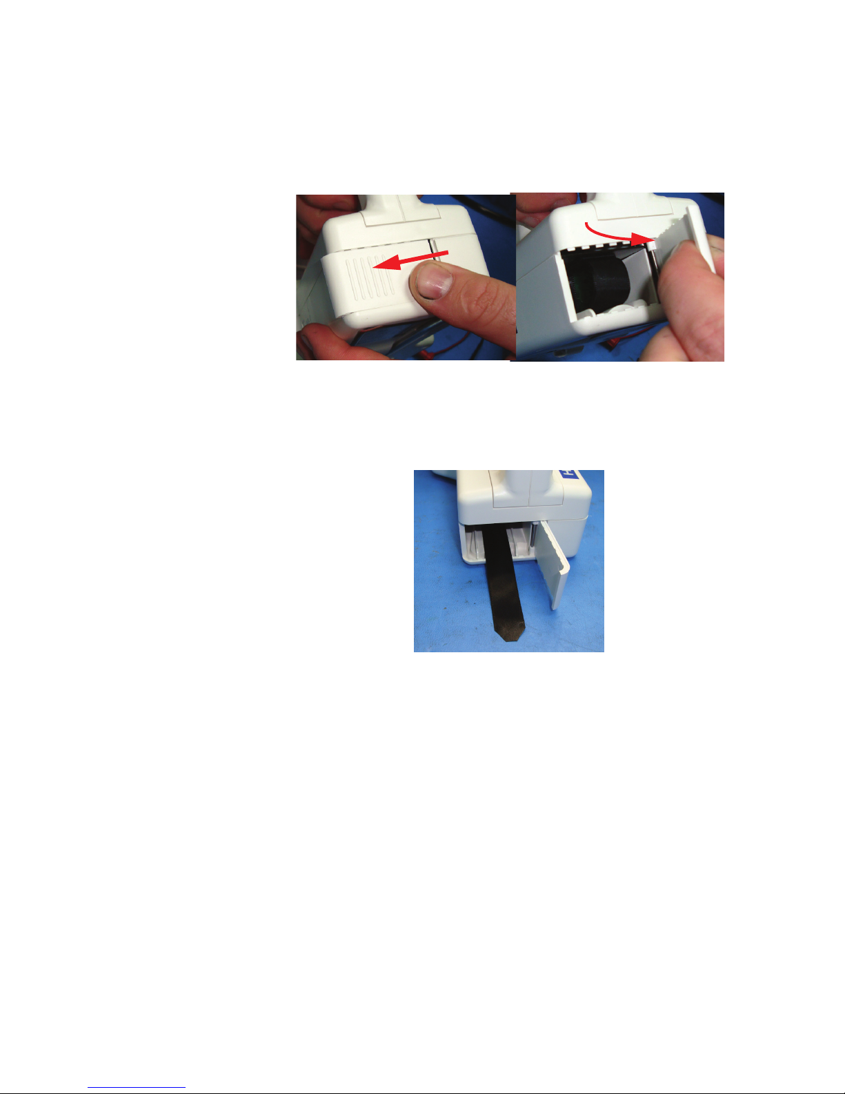
2. Open the battery compartment by sliding the battery compartment
door on the bottom of the unit to the left to unlock it. When the
door is unlocked, open the door. The hinge is on the right side of
the door. See Figure 3-1.
Figure 3-1 Open the Battery Compartment Door
3. Pull the battery release ribbon out of the battery compartment as
shown in Figure 3-2.
3-4
Figure 3-2 Pull Battery Release Ribbon Out
4. Hold the battery connector side toward the HANDHELD. Place
the battery into the compartment, on top of the release ribbon.
Push the battery fully into the compartment until it connects and
is entirely inside the battery compartment. See Figure 3-3.
248083400-1 Rev 7
Page 23

Unpacking, Inspecting and Installation
Figure 3-3 Insert Battery into Battery Compartment
5. Tuck the battery release ribbon over the battery. See Figure 3-4.
Figure 3-4 Tuck Battery Release Ribbon
6. Close the door so that it is flush with the bottom of the
HANDHELD as shown in Figure 3-5.
Figure 3-5 Close the Battery Compartment Door
7. Slide the battery compartment door to the right until it clicks and
latches. See Figure 3-6.
248083400-1 Rev 7
3-5
Page 24

Lighthouse HANDHELD 2016, 3016, 5016 Gen F Operating Manual
Figure 3-6 Secure the Battery Compartment Door
Connect Power
Connect the power adapter as illustrated in the following steps:
1. Insert the round DC power plug into its receptacle on the left side
of the HANDHELD. See Figure 3-7.
3-6
Figure 3-7 DC Power Plug
2. Push the connector in until fully seated as shown in Figure 3-8.
Figure 3-8 Inserting DC Power Plug.
248083400-1 Rev 7
Page 25

Unpacking, Inspecting and Installation
3. Plug the adapter’s AC power cord into the AC power source. The
battery will begin and continue to charge until it is fully charged
or DC power is removed.
WARNING:
ship the instrument with
the battery installed.
Do not
Battery Removal
1. To remove the battery, open the door to the battery compartment
by sliding the door to the left to unlatch it. See Figure 3-9.
Figure 3-9 Unlatch Battery Compartment Door
248083400-1 Rev 7
3-7
Page 26

Lighthouse HANDHELD 2016, 3016, 5016 Gen F Operating Manual
2. Swing the battery compartment door open as shown in Figure 3-
10.
Figure 3-10 Open Battery Compartment Door
Note: Remove the
battery if the instrument will
be stored for a month or
longer. Leaving the battery
in during storage will drain
the battery to the point
where it will not recharge.
3. Hold the instrument securely then pull the battery release ribbon
outward to disconnect the battery and slide the battery out.
Remove the battery. See Figure 3-11.
Figure 3-11 Remove Battery
3-8
248083400-1 Rev 7
Page 27

Unpacking, Inspecting and Installation
Optional Printer Accessory
An optional external thermal printer can be used with the HANDHELD
to print reports directly from the instrument.
Connect the external printer as illustrated in the printer Read Me First,
document #248083378-1, which is included on the Operating Manual
CD.
Figure 3-12 HANDHELD External Printer
248083400-1 Rev 7
3-9
Page 28

Lighthouse HANDHELD 2016, 3016, 5016 Gen F Operating Manual
Connecting to an External Computer or Facility
Management System
The HANDHELD has the ability to be connected to the Lighthouse
Monitoring System (LMS), LMS Express or LMS XChange Data
Transfer Software to download its data.
By transferring the instrument’s data to the Lighthouse Monitoring
System (LMS) or a PC running LMS Express, historical data can be
stored externally for future reviewing and trending. LMS XChange
software can export data to a *.csv file for historical review.
Note:
can be used for the printer
or to connect HANDHELD
to an external computer. It
cannot be used to connect
to both at the same time.
The DATA port
Note: LMS Express
allows you to upload data
from your HANDHELD;
LMS Express RT allows
you to also collect data in
real time.
1. To connect to the HANDHELD, insert the RJ45 end of the
HANDHELD data communications cable to the DATA port as
shown in Figure 3-13.
Figure 3-13 Connecting RJ45 Data Communications Cable
2. Connect the other end of the data communication cable to your
Lighthouse Monitoring System or PC running LMS Express or
LMS XChange software.
Please refer to the LMS XChange, LMS Express or LMSNet manual
for additional information.
3-10
248083400-1 Rev 7
Page 29

00
4 Operation
This chapter describes how to use the HANDHELD 2016, 3016 and
5016 Airborne Particle Counters.
Using the
Instrument
WARNING:
attempt to sample
reactive gases (such as
hydrogen or oxygen)
with this instrument.
Reactive gases create an
explosion hazard in the
instrument.
Sampling any gas under
pressure can damage the
instrument and void the
warranty.
Sampling any gas that is
not the same density as
ambient air can result in
inaccurate data.
Contact Lighthouse for
more information.
Do not
The HANDHELD comes with a charged battery and is ready for use.
To start using the instrument, proceed as follows:
1. Insert the battery included with the shipment. (See Chapter 2 for
instructions.)
2. Position the instrument in the environment to be measured.
3. Remove the protective cap from the inlet tube. To use the
provided isokinetic probe, install it by connecting to inlet tube on
the top of the instrument. NOTE: Do not discard the protective
cap. It should be placed on the inlet tube any time the
instrument is moved outside the environment being
measured.
4. The included Temperature/Relative Humidity probe can be
attached to the provided receptacle to read environmental data.
5. Set on/off switch found on the left side of the unit to ON.
6. The Start Up screen displays on the LCD.
WARNING:
allow water, solvents, or
other liquids enter the
instrument via the inlet
tube - the instrument will
be damaged and void the
warranty.
Do NOT operate the
instrument with the inlet
tube capped or plugged the internal pump will be
damaged and void the
warranty.
248083400-1 Rev 7
Do NOT
7. The MAIN screen appears.
8. On the touch screen, press the START button to start the
9. “STARTING” will display when the pump is initially turned on.
instrument.
4-1
Page 30

Lighthouse HANDHELD 2016, 3016, 5016 Gen F Operating Manual
10. When the HANDHELD starts counting, “COUNTING” appears
on the display. Particle counts are displayed according to the size
of each particle.
Note:
requires a minimum of 5
seconds to ramp up to full
flow. Refer to “Pump
Startup” on page 35.
The pump motor
Touch Screen
Overview
11. If the instrument is in AUTO mode with cycles and a hold time,
“HOLDING” will display after each cycle and “FINISHED” will
display when all the cycles are complete.
12. Press the “STOP” button to stop the instrument before the cycles
are complete.
The HANDHELD incorporates a unique touch screen interface to
control and configure the instrument.
This interface allows the user to easily view and configure the
instrument to specific needs and applications. See Figure 4-1.
Menu Map
4-2
Figure 4-1 Menu Map
248083400-1 Rev 7
Page 31

MAIN Screen
Operation
Note: The Screen Shots
shown in this chapter were
taken from the 3016
model. The 2016 and 5016
screens are identical
except for the channel
sizes.
The MAIN screen gives the user a single snapshot view of the status of
the instrument. The instrument can be powered by a power supply or
from a removable battery. When a battery is used, the battery indicator
will show the level of the battery charge remaining. See Figure 4-2 &
Figure 4-3.
Figure 4-2 MAIN Screen - Battery Operation
When the AC/DC indicator symbol is displayed, it indicates that the
instrument is getting its power from an AC source.
248083400-1 Rev 7
Figure 4-3 MAIN Screen - AC Operation
4-3
Page 32

Lighthouse HANDHELD 2016, 3016, 5016 Gen F Operating Manual
The MAIN screen displays the following options and information.
• LOCATION: Displays the location that is currently being
measured. Up to 200 alphanumeric locations can be configured.
• LOCATION SELECT button: Allows user to change location
before sampling.
• RECIPE button: Allows the user to view, load and unload recipes
that have been configured and saved in the recipe data base.
• PRINT LAST RECORD: Prints the last recorded sample using
the current configuration to determine the type of data printed (i.e.
cumulative vs. differential, raw vs. normalized, ft
The print configuration is set through the PRINT SETUP button in
the Configuration screen. For more details about printing, see the
Configuration section later in this chapter.
3
vs. m3).
Note:
in the battery indicator
while the instrument is
counting, the pump will
stop automatically to
prevent the battery from
discharging completely.
If the “X” appears
• Date/Time: Displays the current date and time.
• Battery Indicator: Indicates that the instrument is being powered
by a rechargeable battery. The amount of battery life left is denoted
by the fill inside the battery icon. When the battery is low, the
words “BATT LOW!” will appear on the screen and the unit will
beep continually until it is plugged into its AC power cord for
recharging. See Figure 4-4.
Figure 4-4 Battery Indicator Levels
• AC Indicator: Indicates that the instrument is being powered with
its AC power cord. If the battery is installed, the HANDHELD will
charge the battery when the instrument is plugged in.
• Flow Status: When the instrument is sampling, the Flow Indicator
will display sufficient or insufficient flow.
WARNING: If the Air Flow is insufficient, turn the instrument off and
contact Lighthouse Worldwide Solutions tech support.
4-4
248083400-1 Rev 7
Page 33

Operation
• Service Indicator: Indicates that the instrument may be in need of
service. If wrench displays, please contact your authorized
Lighthouse Service Provider for assistance or send an e-mail to
techsupport@golighthouse.com.
• μ: The mu symbol indicates the particle sizes, in micrometers,
configured for the instrument. These sizes are pre-configured at the
factory. To order an instrument with different sizes, please contact
a sales representative at Lighthouse ((800) 945-5905 Toll Free).
• DATA DISPLAY: This indicates whether the counts are being
displayed in Differential (Diff) mode or in Cumulative (Cuml)
mode and when the counts are normalized to ft
3
or m3.
• Analog Data: Gives a snapshot view of the enabled analog
channels. (Analog channels are enabled by default.)
•MODE: Displays the current mode selected; possible modes are
AUTO, MANUAL, CONCEN (Concentration) and BEEP.
Note:
greater than 1 minute, the
pump will stop during that
time. At the end of the hold
time, the pump will restart.
If Hold time is
•CYCLES: Indicates the number of times that the count will be
taken at a given location in Auto mode. “1/ 3" indicates that the
count is the first of three samples to be recorded at this location.
The maximum number of cycles is 999. When set to 0, the unit will
run in Auto mode continuously until the STOP button is pressed.
• SAMPLE: The Sample Time (hh:mm:ss) is the duration of one
counting cycle. The Sample Time will count down on the MAIN
screen when the instrument is in AUTO or Manual mode so you can
see how much time is remaining in the sample period. In
Concentration mode, the Sample Time will count up to 6 seconds
per cycle.
•HOLD: Displays the hold time in between cycles. The maximum
hold time is 99 hours, 59 minutes, 59 seconds.
•RECS: This displays the current number of records stored in the
instrument and the total number of records that can be stored. The
data buffer is a circular buffer. The HANDHELD can store up to
3000 records. An asterisk (*) will appear in front of counts when
the buffer wraps.
248083400-1 Rev 7
4-5
Page 34

Lighthouse HANDHELD 2016, 3016, 5016 Gen F Operating Manual
Note: There is a one
second startup during
which the pump is
accelerating to full power.
During this time, the word
“STARTING” will display.
•START/STOP: Press START button on the screen to start
counting. When running, the instrument will display
“COUNTING” in the lower right portion of the screen as shown in
Figure 4-5.
Figure 4-5 Main Screen, Counting Mode
Press the STOP button to stop counting; the word “STOPPED” will
display.
4-6
248083400-1 Rev 7
Page 35

Operation
LOCATION Selection
Changing Locations
The location number for the environment to be measured can be
changed by pressing the LOCATION button at the top of the MAIN
screen. The Select Location screen opens as shown in Figure 4-6.
Figure 4-6 Location Select Screen
• The blue highlight indicates which location is currently selected.
• Use the UP and DOWN arrows to select a location. The single
arrows will move the cursor up and down by a single line.
Locations can also be selected by touching the location name on the
screen.
• Recipes associated with a specific location may also be loaded
when that location is selected.
• The AUTO INC button, when activated will allow the user to
advance to the next location once the current cycle is completed.
• Press the MAIN button to return to the MAIN screen. Whichever
location is currently selected will be the location displayed on the
MAIN screen.
Locations in AUTO Mode
• When the instrument is in Automatic Mode and the START button
is pressed, the instrument will start counting particles automatically
according to the SAMPLE time, HOLD time and number of cycles
that are configured.
248083400-1 Rev 7
4-7
Page 36

Lighthouse HANDHELD 2016, 3016, 5016 Gen F Operating Manual
Zoomed Data View
Press anywhere in the Particle Data area to display the Zoomed view.
See Figure 4-7.
4-8
Figure 4-7 Zoomed Data View
248083400-1 Rev 7
Page 37

Operation
In Figure 4-8, the following functions can be performed using the
toggle buttons on the right side bar:
START or STOP counting
Display Particle data or Analog data
Display Cumulative / Differential data
Display Raw / Normalized particle data
3
Display ft
/ m3 when configured
PRINT the last record
Figure 4-8 Zoomed Data View Buttons
When the instrument is STOPPED or HOLDING, press anywhere in
the white data area to return back to the MAIN screen.
248083400-1 Rev 7
4-9
Page 38
Lighthouse HANDHELD 2016, 3016, 5016 Gen F Operating Manual
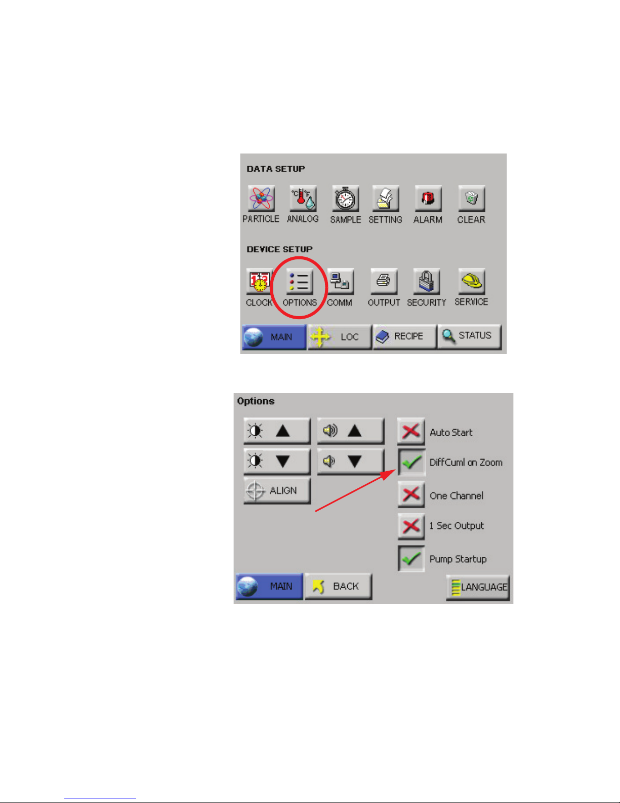
Viewing Two Columns of Data
The unit can display both Differential and Cumulative data at the same
time on the Zoomed View screen. To enable this feature, go to the
CONFIG: Options screen as shown in Figure 4-9.
Figure 4-9 CONFIG: Options Button
Figure 4-10 CONFIG: Options Screen
4-10
248083400-1 Rev 7
Page 39

Operation
START/STOP counting
Display Particle data or Analog data
PRINT the last record
Display Raw / Normalized particle data
Display ft
3
/ m3 when configured
Select the button “DiffCuml on Zoom” as shown in Figure 4-10; this
will display both differential and cumulative data on the Zoomed View
screen as shown in Figure 4-11.
Figure 4-11 Differential and Cumulative Data in Zoomed View
The buttons available when touching the data area of the screen after
selecting DiffCuml on Zoom are shown in Figure 4-12. Note the
selections are different but their functions are the same as on dual
display screen.
248083400-1 Rev 7
Figure 4-12 Diff / Cuml Screen Button Actions
4-11
Page 40

Lighthouse HANDHELD 2016, 3016, 5016 Gen F Operating Manual
To return the instrument to the default single-column zoom view, return
to the MAIN Screen view, press CONFIG, Options and deselect the
button “DiffCuml on Zoom” button. See Figure 4-13.
Figure 4-13 DiffCuml on Zoom Disabled
Select the MAIN button to return to the MAIN Screen view or press
BACK to return to the previous level. Here, the user can choose what
data type is to be displayed in one column on the Zoomed View screen.
Go to the CONFIG: Settings screen and select Differential or
Cumulative for the data type. SeeFigure 4-14 .
4-12
Figure 4-14 Configuration: Setting Screen
248083400-1 Rev 7
Page 41

Operation
Press the MAIN button, then tap in the data area to go into the Zoomed
View. See Figure 4-15.
Figure 4-15 Zoomed View with Only Cumulative Data
Only one column of data is displayed.
CONFIGURATION
Screen
Press CONFIG on the MAIN screen to display the Configuration
screen as shown inFigure 4-16 .
Figure 4-16 Configuration Screen
Data Setup includes buttons to enable/disable particle channels,
configure analog temperature readings, set sample record parameters,
sample settings, thresholds, enable/disable alarms, and clear the data
buffer.
Device Setup includes buttons to configure the instrument’s date and
time, set the LCD contrast, adjust the instrument’s beep volume, enable
the instrument to AutoStart, set it to display only one channel of data,
enable 1 Second Output, set the instrument’s communication address,
enabling print functions, enable password restrictions, and/or (with
proper authorization) adjust service settings.
248083400-1 Rev 7
4-13
Page 42

Lighthouse HANDHELD 2016, 3016, 5016 Gen F Operating Manual
DATA SETUP Figure 4-17 displays the Data Setup option buttons. These options
allow the user to configure the parameters for data collection during a
sample.
Figure 4-17 Data Setup Options
Particle Channels
The instrument’s particle channels can be enabled or disabled on the
Particle Channel. A checkmark is displayed next to each enabled
channel as shown in Figure 4-18.
Note: The data buffer is
cleared when channels are
enabled or disabled. This
ensures that all of the data
in the buffer will have the
same number of channels.
4-14
• The checkmark button next to each channel size is a toggle. Press it
Figure 4-18 Particle Channel Configuration
once to disable a channel and a red “X” will display, indicating that
the channel is disabled. Press the button again and it will change
back to the checkmark, enabling the channel.
248083400-1 Rev 7
Page 43

Operation
• Pressing MAIN or BACK will prompt to clear all collected data as
shown in Figure 4-19.
Figure 4-19 Clear Data Screen
• From this screen, press CANCEL to cancel changes and return to
the Configuration screen.
When channels are disabled, they are removed from the MAIN screen
display, from the reports, and from the printouts.
The channel size for disabled channel(s) remain in the Data screen,
however the instrument does not record data for disabled channels.
Analog Channels
A Temperature and Relative Humidity probe can be connected to the
HANDHELD via a connector on the top of the unit.
Users can select if the HANDHELD displays analog temperature data
as Fahrenheit or Celsius by pressing the ANALOG button on the
Configuration screen. The Select Temperature Units window displays.
There are two buttons on the Select Temperature Units window. The
button displayed shows the units that are currently selected: F for
Fahrenheit and C for Celsius.
248083400-1 Rev 7
4-15
Page 44

Lighthouse HANDHELD 2016, 3016, 5016 Gen F Operating Manual
To change to Celsius, press the C button. To change to Fahrenheit,
press the F button. See Figure 4-20 & Figure 4-21.
Figure 4-20 Analog Channels - Select Celsius Units
4-16
Figure 4-21 Analog Channel - Select Fahrenheit Units
248083400-1 Rev 7
Page 45

Operation
Temperature and relative humidity values appear on the MAIN screen
with the units you selected as shown in Figure 4-22.
Figure 4-22 Analog Data on MAIN Screen
When the unit is not counting or when it is holding, you can display the
instrument’s current Analog data by pressing press anywhere in the
Particle Data area to bring up the Zoomed Data View, then press the
Analog toggle button to display Analog data. See Figure 4-23.
Figure 4-23 Zoomed Data View: Analog Data
248083400-1 Rev 7
4-17
Page 46

Lighthouse HANDHELD 2016, 3016, 5016 Gen F Operating Manual
SAMPLE
Configure the Sample Time and the number of samples to be collected
on the Sample screen as shown in Figure 4-24.
Note:
immediately when START
is pressed. If a Start Delay
is required, the Delay
should not be set to less
than 5 seconds or readings
may be unreliable.
The pump starts
Figure 4-24 Sample Timing Configuration Screen
•CYCLES: The number cycles is set to determine how many times
the instrument samples the air in a single location. This is used only
in AUTO mode. The range is 0 - 999. When Cycles is set to 0, the
instrument will continue running samples indefinitely until the
STOP button is pressed.
Select the CYCLES button; enter the number of desired cycles
using the numeric keypad on the right. Press ERASE to erase a
number, if needed. Press ENTER to set the Cycles.
• DE LAY: The Initial Start Delay (hh:mm:ss) is the time between
pressing the START button and the unit actually starting counting.
The Initial Start Delay gives the operator time to exit the area under
test so that the measurement is taken under a controlled condition.
The maximum delay time is 99 hours, 59 minutes and 59 seconds.
Select the DELAY button; enter the initial delay time in hours,
minutes and seconds using the numeric keypad on the right.
4-18
After the value is entered, press ENTER.
248083400-1 Rev 7
Page 47

Operation
Note: If the Hold time is
set to 00:00:00 in Auto
Mode, the instrument will
run the samples according
to the sample time and the
# of cycles, but with no
hold time in between
cycles.
Note:
greater than one minute,
the pump will shut off
during the specified hold
time.
Note:
Sample Time is 23:59:59.
If the Hold time is
The maximum
The maximum hold time is 99 hours, 59 minutes and 59 seconds.
This field will count down to indicate how much time is left for the
Hold period.
Select the HOLD button; enter the time in hours, minutes and
seconds using the numeric keypad on the right. Press ERASE to
erase a number, if needed. Press ENTER to set the Hold Time.
• HOLD: The Hold Time (hh:mm:ss) is the time between count
cycles when the instrument is not counting particles.
• SAMPLE: The Sample Time (hh:mm:ss) is the duration of one
counting cycle. The Sample Time will count down on the MAIN
screen when the instrument is in Auto or Manual mode to indicate
how much time is remaining in the Sample.
Select the SAMPLE button; enter the time in hours, minutes and
seconds using the numeric keypad on the right. Press ERASE to
erase a number, if needed. Press ENTER to set the Sample time.
Note:
volume is ft
sample volume is 0.1 ft
When the particle
3
the minimum
• SAMPLE VOLUME: Instead of selecting a specific Sample Time,
3
.
the instrument can be set to measure a specific Sample Volume in
cubic feet (ft
3
), cubic meters (m3) or liters (l). When this is set, the
corresponding Sample Time will automatically be set. See Figure
4-25.
248083400-1 Rev 7
4-19
Page 48

Lighthouse HANDHELD 2016, 3016, 5016 Gen F Operating Manual
Note: If the particle
volume is liters or m
sample volume is
displayed in liters.
If the particle volume is
cubic feet (ft
volume is displayed in
cubic feet (ft
3
3
3
), the sample
).
,
4-20
Figure 4-25 Changing Sample Volume unit of measure
Press BACK to return to the Configuration screen or press MAIN to
return to the MAIN screen.
248083400-1 Rev 7
Page 49

Operation
SETTINGS
The instrument can be configured to count in different modes and
formats. See Figure 4-26.
Note:
for Auto, Manual, and
Beep modes count down
and the sample times for
Concentration mode count
up.
The sample time
Figure 4-26 Sample Settings Screen
COUNT MODE
The following modes are available: Auto, Manual, Beep and
Concentration.
• AUTO - When the instrument is in Automatic Mode and the
START button is pressed, the instrument will start counting
particles automatically according to the Sample Time, Hold Time
and the number of Cycles that are configured. If Cycles are set to 0,
the instrument will continue indefinitely in Auto Mode until the
STOP button is pressed.
• MANU (Manual Mode) - When the instrument is in Manual
Mode, it will start counting when START is pressed and stop at the
end of one programmed Sample Time.
• CONC (Concentration Mode) - When the instrument is in
Concentration mode, it gives a calculated value of the concentration
of particles in a volume of air, measured and displayed on the
MAIN screen in either counts per cubic foot or per cubic meter.
Counting starts when the START button is pressed and it will
continue until the STOP button is pressed. The sample time for
Concentration mode is six seconds. As the sample time on the
MAIN screen counts from one to six, the particle counts are
updated continuously.
248083400-1 Rev 7
Concentration data will be recorded and can be viewed in the Data
screen and on the printouts.
4-21
Page 50

Lighthouse HANDHELD 2016, 3016, 5016 Gen F Operating Manual
Note: BEEP mode only
works with CUMULATIVE
data and for Sample Times
greater or equal to 6
seconds.
Note:
works with CUMULATIVE
data.
Note:
set to one count, the beeps
may not be for every single
count.
BEEP mode only
If BEEP mode is
• BEEP - In this mode, the instrument is pre-configured to beep
according to the alarm threshold set in Alarm Configuration and the
instrument’s sample time if the instrument is set to collect
cumulative data. Counting starts one second after the START
button is pressed and will continue until the STOP button is
pressed.
If no channel is set for alarming and BEEP mode is selected, the
smallest channel size will be automatically selected and its alarm
threshold will be used to trigger the alarm.
If alarming is enabled on more than one channel size, only the
smallest channel size will be used to trigger the alarm in BEEP
mode. Larger channel sizes will be ignored.
The data will be recorded based on the set sample time and hold
time and can be viewed in the View Buffer and on the printouts.
There will be no indication on the record, however, that the data
was saved while the instrument was in BEEP mode.
Geiger Counter Mode
While in BEEP mode the instrument can be set to beep 1 to 4 beeps per
second depending on the number of particles the instrument has
counted per second.
To set up the instrument for Geiger Counter Mode:
1. Enable BEEP Mode.
2. Set the smallest particle channel to 1.
In Geiger Counter Mode the instrument will beep from 1 beep up to 4
beeps per second if it counts from 1 particle up to 4 particles per
second. The maximum beeps per second the instrument can emit are 4
per second even if the instrument counts 100 particles per second.
The value set in the smallest particle channel’s alarm is the trigger for a
single beep per second. If the smallest particle channel is set to 2, the
instrument will beep once every second for every 2 particles the
instrument counts per second.
4-22
248083400-1 Rev 7
Page 51

Operation
PARTICLE Display
Data on the instrument can be displayed in Differential (DIFF) or
Cumulative (CUML) counts.
For example, the cumulative count for the 1μm channel is the sum of
that channel’s count + 2.5μm count + the 5μm count.
The differential count for the 1μm channel is the number of particles
between 1μm and 2.5μm.
The data displays on the MAIN screen according to whichever is
selected (DIFF or CUML).
The data format is either Raw (RAW) or Normalized (NORM). Raw
data displays the actual number of particles counted. Normalized data
shows particle concentrations calculated from the raw data based on the
settings chosen (ft
3
or m3).
Volume of Air = Sample time (minutes) x FlowRate (CFM)
Normalized Data = Number of Particles/Volume of Air
Press BACK to return to the Configuration screen or press MAIN to
return to the MAIN screen.
ALARM
The user can enable alarming on specific channels as illustrated in
Figure 4-27.
Threshold Button
248083400-1 Rev 7
Figure 4-27 Particle Alarm Configuration, 2 Channels Enabled
4-23
Page 52

Lighthouse HANDHELD 2016, 3016, 5016 Gen F Operating Manual
Note: Alarming is only
applicable for AUTO and
MANUAL mode. It applies
only to Raw particle counts
even if the instrument is
displaying Normalized
data.
If the instrument is set to
Differential data, the alarm
threshold will apply to the
differential counts.
If the instrument is set to
display Cumulative data,
the alarm threshold will
apply to the cumulative
counts.
To enable the alarming for any channel, press the “X” next to that
channel. When a checkmark is displayed, that channel is enabled for
alarming. Press the checkmark to disable the alarming for that channel.
Alarm Threshold
Press the threshold button next to the enabled channel in order to set the
alarm threshold for that channel. See Figure 4-28.
Note: To receive alarms,
the Sample Time must be
greater than 1 second.
Figure 4-28 Configure Alarm Threshold
Enter the desired alarm threshold for the selected particle channel in
number of particles, then press ENTER. The threshold value will be
updated on the Particle Alarm screen as shown in Figure 4-29.
4-24
248083400-1 Rev 7
Page 53

Note:
triggered per sample
record. At the end of the
sample time, the alarms
reset.
Alarms are
Operation
Press BACK to return to the Configuration screen or press MAIN to
return to the MAIN screen.
Figure 4-29 2 channels Enabled for Alarming
Note:
enabled on two channels, if
the user presses the Alarm
Acknowledge button when
the first channel goes into
alarm, the alarm will not
sound if the second
channel’s threshold is
reached within the sample
period.
If alarms are
When a particle channel that is enabled for alarming goes into alarm,
the selection cursor (>) and the channel size are highlighted in red as
shown in Figure 4-30.
Figure 4-30 Channel in Alarm
When the instrument begins to beep in response to the Alarm settings,
silence the beep by pressing anywhere on the MAIN screen. After
acknowledging the alarm, the count will reset when the next sample
cycle begins.
248083400-1 Rev 7
4-25
Page 54

Lighthouse HANDHELD 2016, 3016, 5016 Gen F Operating Manual
Clear Buffer
Press the Clear Buffer button to clear the instrument’s data buffer. See
Figure 4-31.
DEVICE
SETUP
Figure 4-31 Clear Buffer Screen
Press OK to clear the data or press Cancel to exit screen without
clearing the data.
The Device Setup buttons allow the user to set and adjust how the
instrument operates when running samples. Specific functions can be
enabled and disabled for display options, data output and security. See
Figure 4-32.
Figure 4-32 Device Setup Options
4-26
248083400-1 Rev 7
Page 55

Operation
CLOCK
Use the Clock screen to set the instrument’s date and time. See Figure
4-33.
Figure 4-33 Date & Time Configuration Screen
Set the instrument’s Date by entering values for the desired month, day
and year and then press the ENTER button.
248083400-1 Rev 7
4-27
Page 56

Lighthouse HANDHELD 2016, 3016, 5016 Gen F Operating Manual
Note:
MONTH 1ST (M / D/
Y) is the default date format.
Change the Date’s format by pressing the M / D/ Y button to display the
date as month-first. Alternatively pressing the D / M/ Y button displays
the Date as day-first and the Y / M/ D button displays the date yearfirst. See Figure 4-34 and Figure 4-35.
Figure 4-34 Date Option: Day First
Figure 4-35 Date Option: Year First
4-28
248083400-1 Rev 7
Page 57

Set the instrument’s Time by pressing the TIME button. See
Figure 4-36.
Figure 4-36 Configuring TIME
Operation
Enter the desired Time in hours, minutes and seconds then press
ENTER to save the new time.
Press BACK to return to the Configuration screen or press MAIN to
return to the MAIN screen.
248083400-1 Rev 7
4-29
Page 58

Lighthouse HANDHELD 2016, 3016, 5016 Gen F Operating Manual
OPTIONS
Several optional configuration settings are found on the OPTIONS
screen. See Figure 4-37.
Figure 4-37 Options Configuration Screen
CONTRAST ADJUST
The contrast/brightness of the LCD screen can be adjusted by pressing
the first set of UP and DOWN arrows.
AUDIBLE BEEP ADJUST
The audio level of the BEEP can be adjusted by pressing the second set
of UP and DOWN arrows.
ALIGN TOUCH SCREEN
The ALIGN button allows you to re-align the touch screen so the
locations that you touch on the screen correspond to the expected
button or function.
• Press the ALIGN button.
4-30
248083400-1 Rev 7
Page 59
Operation
WARNING: Be
careful to touch the
screen at the specified
locations only. If
touching the screen
elsewhere during this
process, the screen will
be incorrectly aligned.
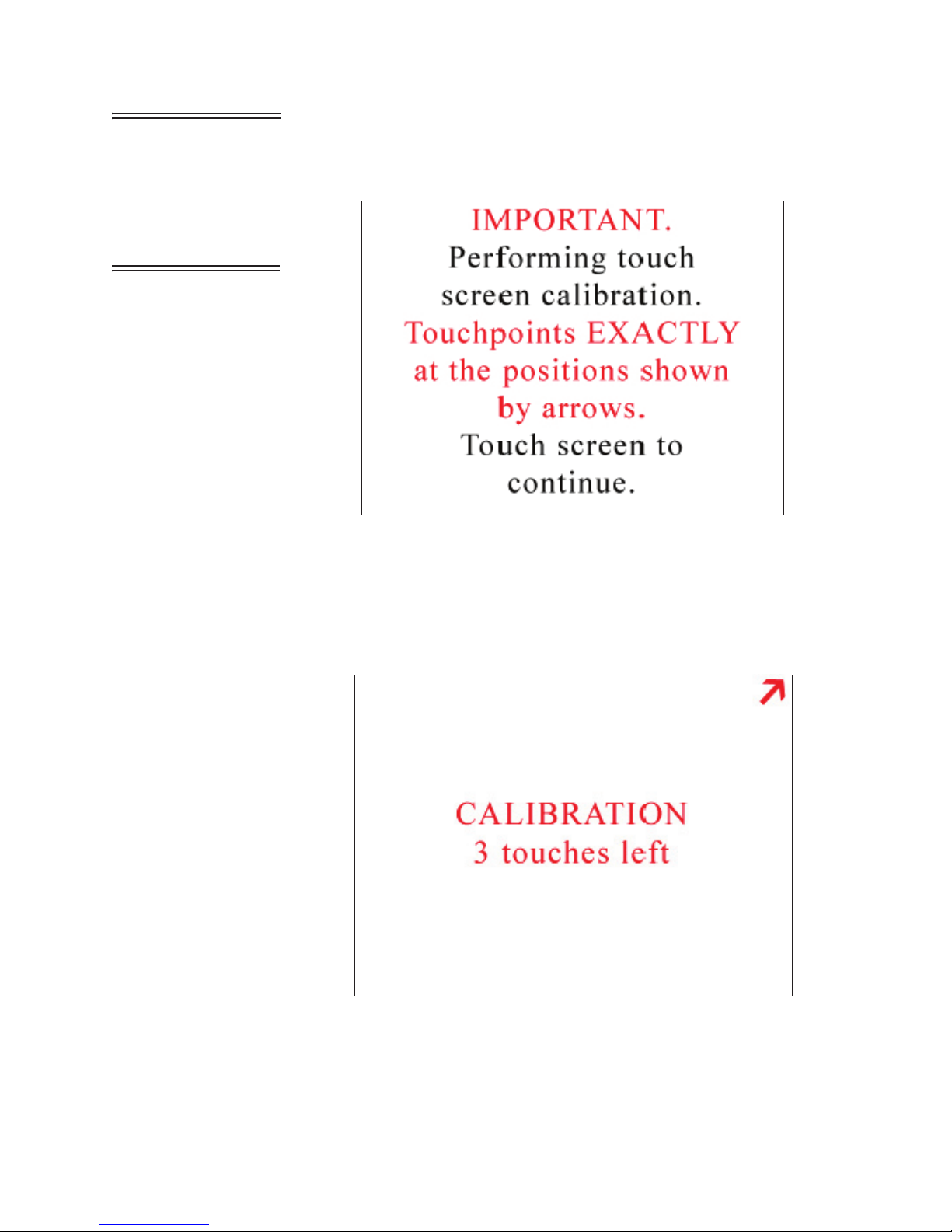
• The screen in Figure 4-38 appears. Touch anywhere on the screen
to continue calibration.
Figure 4-38 Alignment Screen 1
Note:
Using a PDA Stylus
provides higher accuracy to
the touch screen interface.
• At the next screen, touch the arrow displayed in the upper right
corner. This needs to be done a total of three times before
continuing to the next alignment. See Figure 4-39.
Figure 4-39 Alignment Screen 2
248083400-1 Rev 7
4-31
Page 60

Lighthouse HANDHELD 2016, 3016, 5016 Gen F Operating Manual
• The third screen displays the arrow in the upper left corner. The
arrow will have to be touched three times to ensure calibration as
Figure 4-40 illustrates this.
Figure 4-40 Alignment Screen 3
• The fourth alignment screen shown in Figure 4-41, displays the
arrow in the at the bottom center of the screen. Touch the arrow
three times to finish the alignment process.
4-32
Figure 4-41 Final Alignment Screen
248083400-1 Rev 7
Page 61

Operation
Note: The screen
alignment function can
also be accessed by
touching the screen when
powering the instrument
on.
• Once the final alignment is complete, the following screen is
displayed. See Figure 4-42. Touch anywhere in the screen to return
to the OPTIONs screen.
Figure 4-42 Alignment Saved Screen
Autostart Mode
When Autostart mode is enabled, set the Delay time to at least 5
seconds.
If Autostart mode is enabled, when the instrument is powered on (or
regains power after a power outage), the instrument will immediately
begin sampling based its configured mode, delay, start, and hold times.
DiffCuml on Zoom
If DiffCuml on Zoom is enabled, the counter’s display will show two
columns of data simultaneously - Differential and Cumulative.
One Channel
If One Channel is enabled, only the first channel will be displayed on
the MAIN screen. Data will continue to be recorded, printed and
downloaded for all channels.
248083400-1 Rev 7
4-33
Page 62

Lighthouse HANDHELD 2016, 3016, 5016 Gen F Operating Manual
Note: If the first channel
is disabled and One
Channel mode is enabled,
the display and zoomed
data view will be blank.
One Channel mode only affects how data is displayed on the MAIN
screen. Refer to Figure 4-43.
Figure 4-43 Main Screen - One Channel Option Enabled
Note:
Output disables Alarming.
One Second
Note: Changing any
setting (mode, sample
time, hold time, etc)
disables the One Second
Output.
ONE SECOND OUTPUT
If One Second Output is enabled, the instrument’s settings reset to the
following.
• Mode: AUTO
• Cycles: Zero
• Sample Time: One second
• Hold Time: Zero seconds
• Cumulative/Differential: Cumulative (CUML)
• Raw/Normalized: Raw
When counting, the MAIN Screen will update continuously and data
will not be recorded to the data buffer.
4-34
248083400-1 Rev 7
Page 63

Operation
Pump Startup
This is ON by default and sets a three-second pump ramp up time at the
beginning of the first sample, or at the beginning of all samples if the
HOLD time is greater than one minute, to stabilize the laser and air
flow. This setting should be left in the default mode unless special
applications, such as “surface scans”, require it to be disabled.
LANGUAGE
Pressing the LANGUAGE button allows the user to change the
operating language displaying the screen shown in Figure 4-44.
248083400-1 Rev 7
Figure 4-44 Operating Language Selection Screen
Press the desired language button then BACK or MAIN. The default is
English.
4-35
Page 64

Lighthouse HANDHELD 2016, 3016, 5016 Gen F Operating Manual
COMM ADDRESS
When the HANDHELD is connected to a data collection system or
daisy chained at the end of a chain of RS-485 instruments, the
instrument’s COMM address is used to identify it.
LMS XChange or LMS Express/RT will search for the instrument by
the COMM Address specified on the Communication screen shown
below. COMM addresses range from 1 to 63.
For RS-485 communications, each device on a multi-port chain must
have a unique address.
4-36
Figure 4-45 COMM Address Configuration screen
Set the COMM Address by using the numeric keypad to select the
address; press ERASE to erase a number, if needed. Press ENTER to
accept the value. See Figure 4-45.
Press BACK to return to the Configuration screen or press MAIN to
return to the MAIN screen.
248083400-1 Rev 7
Page 65

Operation
OUTPUT SETUP
The Print configuration has several options for printing the data that the
user sets on the Printer Setup screen shown in Figure 4-46.
Note:
both Differential and
Cumulative printing at the
same time. For normalized
values with more than 8
digits, only the whole
number will be printed.
You can select
Figure 4-46 Printer Setup Screen
• Output on Sample / Output on Alarm - When Output on
Sample is enabled, a single record will print at the end of every
sample.
When Output on Alarm is enabled, a single record printout will
print at the end of any sample that experiences an alarm condition.
• Model Name - When enabled, the Model name of the instrument
will print in the header of all printouts.
• Serial Number - When enabled, the Serial Number of the
instrument will print in the header of all printouts.
• Separator - When enabled, a line separator will print after the
Model Name and Serial Number in the header of all printouts.
• Differential / Cumulative Toggle - This toggle option specifies
how the data will appear on the printouts.
Press BACK to return to the Configuration screen or press MAIN to
return to the MAIN screen.
248083400-1 Rev 7
4-37
Page 66

Lighthouse HANDHELD 2016, 3016, 5016 Gen F Operating Manual
SECURITY
To restrict access to the instrument and/or configuring the instrument,
the HANDHELD has two different password levels. See Figure 4-47.
Figure 4-47 Security Password Configuration Screen
To restrict who can operate the instrument, enable the POWER ON
password. When the POWER ON password is enabled, in order to use
the instrument the user will be required to enter the correct password
each time the instrument is turned on.
To restrict who can configure the instrument, enable the Configuration
(CFG) password. When the Configuration password is enabled, the
user will be required to enter the correct password before they can
access the Configuration screen.
• To set the password for the POWER ON, select the POWER ON
button, then type in a password using the numeric keypad. Press the
ERASE button to delete the last character, if needed.
• Press ENTER to save.
• To set the Configuration (CFG) password, select the CFG button,
then type in a password using the numeric keypad.
• Press the ERASE button to delete the last character, if needed.
• Press ENTER to save the changes.
• Press the “X” button to enable either or both passwords.
Press BACK to return to the Configuration screen or press MAIN to
return to the MAIN screen.
4-38
248083400-1 Rev 7
Page 67

POWER ON PASSWORD
Operation
WARNING:
record the unit’s passwords
in a safe place. If the
password is lost or
forgotten, contact
Lighthouse technical
support for assistance. The
unit may have to be
returned to the factory to
reset the password.
Be sure to
To require that a password must be entered before the instrument can be
used, enable the POWER ON password. See Figure 4-48.
Figure 4-48 POWER ON Password Access Screen
When the POWER ON password is enabled, you will see a password
access screen just after you turn the unit on. The instrument will remain
locked until the correct password is entered.
CONFIGURATION PASSWORD
The Configuration password prevents unauthorized access to the
Configuration screen. See Figure 4-49.
Figure 4-49 CONFIGURATION Password Access Screen
248083400-1 Rev 7
4-39
Page 68

Lighthouse HANDHELD 2016, 3016, 5016 Gen F Operating Manual
SERVICE
This section of the Configuration screen is reserved for Lighthouse
Authorized Service Providers only. The correct service password must
be entered to access this area.
Three options on the lower CFG screen, STATUS, RECIPE and LOC
display the instrument’s current status, configure user recipes and
locations respectfully.
STATUS Touching the STATUS button displays the instrument programmed
version of the various firmware modules as shown in Figure 4-50. This
information is useful when contacting Lighthouse Technical Support
personnel.
4-40
Figure 4-50 HANDHELD 3016 STATUS Screen
248083400-1 Rev 7
Page 69

Operation
RECIPE Selecting the RECIPE button displays the Recipe setup screen. See
Figure 4-51.
Note:
selected is already
assigned to another recipe
or if there are no available
free locations, the user will
not be able to add a new
recipe. The “Add” button
will not be displayed.
If the location
Figure 4-51 Recipe Setup Screen
The Recipe feature allows the user to save instrument settings for
sampling and reports in a database that can store up to 50 recipes.
Selecting the ADD button displays the RECIPE text screen. See Figure
4-52. The recipe can be named using up to 12 characters.
248083400-1 Rev 7
Figure 4-52 Recipe Name Screen
4-41
Page 70

Lighthouse HANDHELD 2016, 3016, 5016 Gen F Operating Manual
Pressing the ENTER button will add the recipe to the database and
display the recipe CONFIG screen as shown in Figure 4-53. Each
option allows the user to configure the instrument to the current recipe.
Figure 4-53 Recipe Configuration
Press the BACK button to save the settings and return to the RECIPE
screen.
Pressing the EDIT button on the main RECIPE screen will allow the
user to change settings on the highlighted recipe.
The LOAD and UNLOAD buttons add or remove the highlighted
recipe as the instrument’s current operating configuration.
The DELETE button will delete any highlighted recipes from the
database.
4-42
248083400-1 Rev 7
Page 71

Operation
The VIEW button displays the current settings for the highlighted
recipe. See Figure 4-54.
Figure 4-54 Recipe - Channel Settings
Press the NEXT button to view the analog and output settings. See
Figure 4-55.
248083400-1 Rev 7
Figure 4-55 Recipe - Analog & Output Settings
4-43
Page 72

Lighthouse HANDHELD 2016, 3016, 5016 Gen F Operating Manual
LOCATION The HANDHELD allows up to 200 different locations and associated
alphanumeric labels.
Press the LOC button on the Configuration screen to display the Select
Location screen as shown in Figure 4-56.
Figure 4-56 LOCATION Setup Screen
On the Select Location screen, the Location name can be selected using
the UP and DOWN arrows or by touching the location name on the
screen.
The following options can be enabled to configure locations for the
HANDHELD.
• When enabled, the Auto Increment option will automatically select
the next location after completing the programmed number of
cycles. The default position is “off” when the unit is powered up.
• The unit can be configured for a maximum of 200 Locations. Each
location name can be configured with a maximum of 8 characters
per name.
• Recipes associated with a specific location are denoted by an
asterisk (*) to the right of the location name.
4-44
248083400-1 Rev 7
Page 73

Operation
• When selecting a location with a recipe, the user is provided with
the option of loading the recipe as shown in Figure 4-57. If the user
chooses not to load the recipe, the location can still be used with the
current settings.
Figure 4-57 Location - Load Recipe
• If a recipe is loaded and a location is selected that is not associated
with a recipe, the user is given the option to unload the current
recipe. If the user chooses to keep the loaded recipe, the location
will adopt the current recipe settings.
To create a name for a location, press the EDIT button to display the
Edit screen. See Figure 4-58.
248083400-1 Rev 7
Figure 4-58 LOCATION Edit Screen
4-45
Page 74

Lighthouse HANDHELD 2016, 3016, 5016 Gen F Operating Manual
• Type in the name of the location using the alphanumeric and
underscore keys.
• Press the ERASE button to erase the last character typed, if needed.
• Press ENTER.
• Use the Arrow keys to go to the next location to be edited and press
the EDIT button. Continue in the same way to edit as many
Locations as desired.
Press the BACK button to return to the Configuration screen or the
MAIN button to return to the MAIN screen.
Activating the AUTO INC button allows the user to select the next
location once the number of cycles is completed.
• The user is prompted to move to the next location after the
programmed number of cycle. See Figure 4-59.
The Auto Increment mode will select the next corresponding location
and continue to sample using the current configuration. If the current
location is using a recipe, the user will be prompted to unload the recipe
before moving to the next location.
4-46
Figure 4-59 Auto Increment Prompt
248083400-1 Rev 7
Page 75

Operation
Data View
Buffer Screen
Data that is stored on the instrument is viewed in the Data Screen.
When the buffer has filled to its limit of 3000 records, the newest
records will overwrite the first records stored. The word “Records” on
the MAIN screen will have an asterisk (*) next to it to indicate that the
buffer has wrapped. When you go to the Data screen after the data has
wrapped, the first record viewed will be the most current record, which
will not necessarily be record #1.
If the Particle Volume is set to ft
display and print in ft
3
. If the Particle Volume is set to m3 or Liters (L),
3
, then the concentration data will
then the concentration data will display and print in m3.
Press the DATA button on the MAIN screen to display the Data screen.
Depending on how the HANDHELD is configured, the data will
display in either raw data mode, or be normalized to ft
3
or m3. See
Figure 4-60 & Figure 4-61.
248083400-1 Rev 7
Figure 4-60 Data Screen - RAW Data
4-47
Page 76

Lighthouse HANDHELD 2016, 3016, 5016 Gen F Operating Manual
Scroll through the data using the UP and DOWN arrow buttons.
• The single arrow moves one record at a time.
Note:
has wrapped, the record
that is first displayed in the
Data screen is the first
record in the data buffer .
This may not be Rec#1.
If you press the single
down arrow button once,
the instrument will display
the last record in the data
buffer.
When the buffer
Figure 4-61 Data Screen - Normalized data in ft
3
The Data screen displays the following information for each data
record.
• Rec# - Identifies which record is currently viewed.
• *Recs - Displays how many records are currently stored in the
HANDHELD’s buffer. When there is an asterisk (*) next to the
word “Recs”, this means that the 3000 record data buffer has
wrapped. The basic concept is First In, First Out (FIFO).
• Size - Lists the channel sizes configured on the instrument.
• Diff#, Diff/ft3, Diff/m3 - Indicates that each channel size’s data is
displayed in differential mode. If a channel was disabled, then there
is a blank space in is column; # indicates raw counts; ft
3
and m
3
indicate normalized counts.
• Cuml#, Cuml/ft3, Cuml/m3 - Indicates that each channel size’s
data is displayed in cumulative mode. If a channel was disabled,
there will be a blank space in this column. # indicates raw counts
while ft
3
and m3 indicate normalized counts.
• Loc - Indicates the location at which the data record was recorded.
The Location name listed is the alphanumeric label that was saved.
• Smpl - Indicates the Sample Time (HH:MM:SS) at which the data
• Date - Indicates the instrument date on which the data was
4-48
record was sampled.
recorded. The date will display in the format selected in the
configuration (MM/DD/YYYY, DD/MM/YYYY or YYYY/MM/
DD).
248083400-1 Rev 7
Page 77

Operation
• Time - Indicates the instrument time at which the data was recorded
(HH:MM:SS).
• Instr - Indicates the state of the instrument at the time the data was
recorded. Instrument states include GOOD or SRVC.
If SRVC appears, printouts will say “Service Required” and the
sensor may need cleaning. Please contact Lighthouse Technical
Support at 800-945-5905 (USA Toll Free), 541-770-5905 (Outside
of USA).
• Flow - Indicates the flow state of the instrument at the time the data
record was recorded. Flow is recorded as OK or ALRM. If the flow
was in alarm, it will print as Flow: Alert on the printouts.
• Alarm - Indicates (NONE or YES) if the data record exceeded any
of the alarm thresholds of any of the channels that were enabled for
alarms. If the data record exceeded alarm thresholds, printouts
show “Alarm: Yes”.
• Laser - Indicates the status of the laser at the time the data record
was recorded; possible laser states include OK or SRVC. If the laser
needs to be serviced, it will print as Laser: Service.
If laser state is SRVC, please contact Lighthouse Technical Support
at 800-945-5905 (USA Toll Free), 541-770-5905 (Outside of USA).
Printing Data
View Buffer
Report
Analog Data
If the Temperature/Relative Humidity probe is attached during data
recording, the analog data will be listed in the Data screen as A1
(Temperature) and A2 (Relative Humidity).
The instrument stores up to 3000 records in its data buffer. The Buffer
Report prints all or a range of the records in the buffer in the format
specified by the selections in the Configuration.
At the end of the Buffer Report, the following summary information is
printed.
• Data displayed in Cumulative or Differential mode
• Raw (“Particle Counts”) or Normalized (“Particles/ft
3
” or
“Particles/m3”)
• # of samples in the report
• For each channel size:
• Maximum Value
248083400-1 Rev 7
• Minimum Value
• Average
• Standard Deviation
4-49
Page 78

Lighthouse HANDHELD 2016, 3016, 5016 Gen F Operating Manual
**HANDHELD**
Serial #: 30804001
----------------------Location: 29
08-02-03, 15:34:46
Sample Time: 00:01:00
Flow: 0.1 cfm
Laser: OK
74.7 DegF 52.2 %RH
Particle Counts:
Size Diff Cumul
0.3 29118 32543
0.5 2572 3425
1.0 797 853
3.0 29 56
5.0 24 27
**HANDHELD**
Serial #: 30804001
----------------------Location: 29
08-02-03, 15:34:46
Sample Time: 00:01:00
Flow: 0.1 cfm
Laser: OK
74.7 DegF 52.2 %RH
Particles/ Ft^3:
Size Diff Cumul
0.3 2222.0 2350.0
0.5 115.0 128.0
1.0 13.0 13.0
3.0 0.0 0.0
5.0 0.0 0.0
This indicates
whether the data
viewed is in RAW
counts or
Normalized counts.
The UCL calculation will be printed for each channel size if the
number of locations in the range is 2 through 9. The calculation will
only print if the Format settings (Setting screen) are set to CUML and
NORM. Any other format settings or locations less than 2 and greater
than 9 will print N/A for each channel.
View the same data in different formats just by changing the Particle
Display options on the Sample Setting screen.
The Data Summary can be viewed as:
• Raw Counts, Differential Data
• Raw Counts, Cumulative Data
• Normalized Counts, Differential Data, Particles/ft
• Normalized Counts, Differential Data, Particles/m
• Normalized Counts, Cumulative Data, Particles/ft
• Normalized Counts, Cumulative Data, Particles/m
3
3
3
3
PRINT RECORD
When you push the PRINT RECORD button, whatever record is
currently displayed in the Data screen will print as a single sample
record. The record will print according to the settings in the Print
Configuration. See Figure 4-62.
Figure 4-62 Examples of Output from Auto Printout of Sample
4-50
248083400-1 Rev 7
Page 79

Operation
Printing Range
• To print a range of data from the buffer, scroll to the first data
record to be included in the range.
• Press the RANGE button. The following screen will display as
shown in Figure 4-63.
Note: Printing ALL
records may take some
time if the buffer is full.
Figure 4-63 Print Range Screen
• Enter the number of records to print and press the ENTER button.
• Press ALL to print all records in the buffer.
• Press CANCEL to cancel printing.
• Press BACK to return to the View Buffer screen without printing
the report.
248083400-1 Rev 7
4-51
Page 80

Lighthouse HANDHELD 2016, 3016, 5016 Gen F Operating Manual
***** SUMMARY *****
**HANDHELD 3016**
Serial #: 041004001
----Location: LOC002
06-20-2013, 15:34:30
Sample Time: 00:01:00
Flow: 0.1 cfm
Laser: OK
TEMP: 66.77 F
RH: 35.71 %
Particle/ Ft^3:
Size Cumul
0.3 4260.0
0.5 810.0
1.0 580.0
3.0 360.0
5.0 350.0
10.0 310.0
Location: LOC003
Particle/ Ft^3:
Summary (Cuml):
----# of samples =2
Size Max
0.3 4260.0
0.5 810.0
1.0 580.0
3.0 360.0
5.0 350.0
10.0 310.0
Size Min
0.3 3860.0
0.5 750.0
1.0 360.0
3.0 240.0
5.0 180.0
10.0 150.0
Size 95% UCL
0.3 5322.0
0.5 969.3
1.0 1164.1
3.0 678.6
5.0 801.4
10.0 734.8
4-52
Figure 4-64 Sample Buffer Report
248083400-1 Rev 7
Page 81
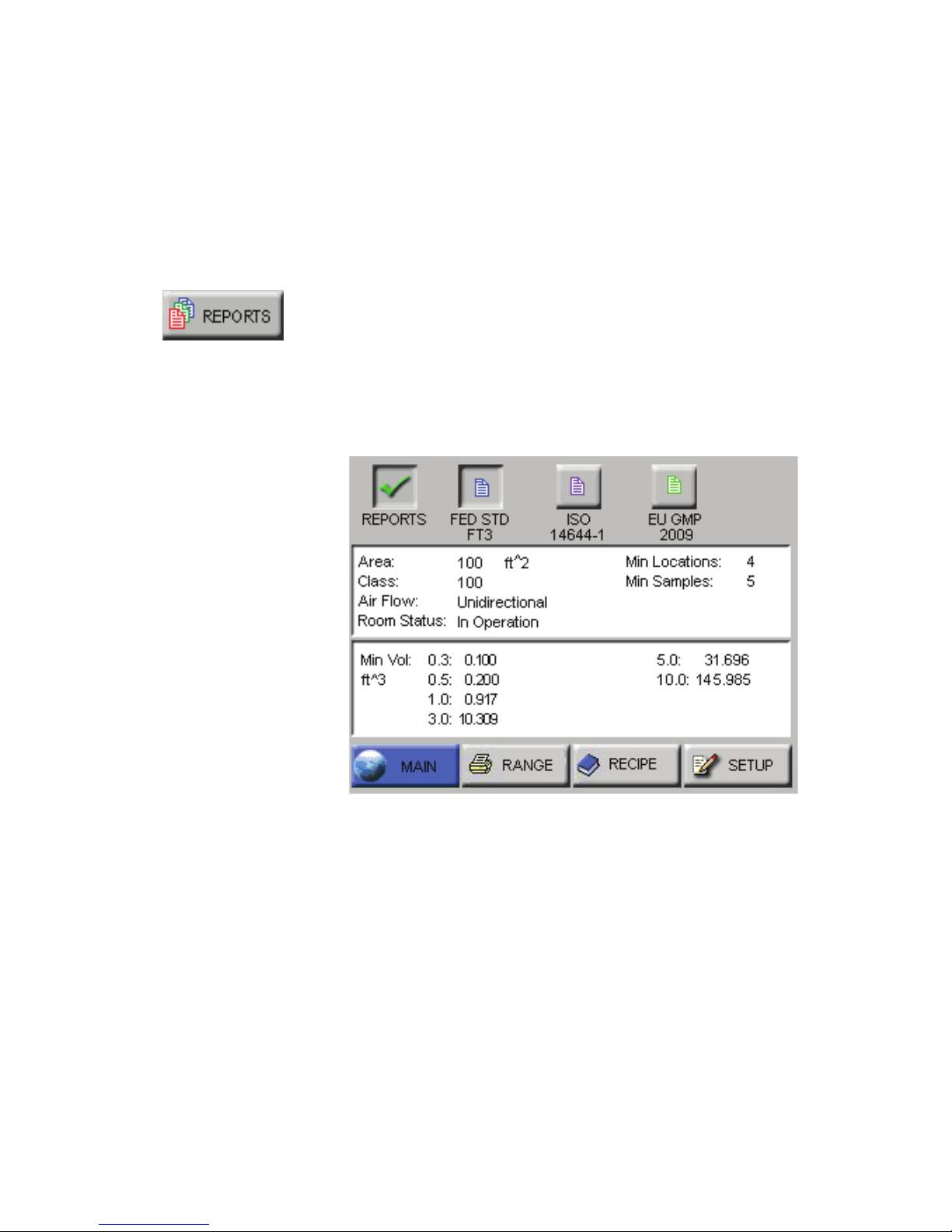
Operation
REPORTS The HANDHELD can print the following Cleanroom Classification to
Standards reports:
Note:
The EU GMP 2009
report is only valid if the
instrument is configured with
the 0.5 and 5.0 micron
channel sizes.
Note:
If the user sets the
counter for a minimum
volume, and takes the exact
number of minimum locations
and samples, the user could
get a “Cannot Classify: too
few locations” error if the
minimum volume rounds the
sample time down so that not
enough samples at the
minimum volume are taken.
In this case, add one or two
seconds to the sample time
so that the user is not at the
exact minimum volume.
Federal Standard ft
3
ISO 14644-1
EU GMP 2009
Reports General Settings
Enable the Reports feature by pressing the red “X” (Default position)
located at the top left of the screen. The button will display a check
mark indicating the feature is enabled. See Figure 4-65.
• Depending on the reports requirements, the number of cycles and
• The number of required locations will be automatically assigned to
• The display format will be changed to Normalized (normalized to
248083400-1 Rev 7
Figure 4-65 Typical Reports Screen
minimum sample time will be calculated when the reports mode is
enabled.
the report. The user may change locations via the reports SETUP
screen.
ft3 for FED-209 and m3 for ISO and EU GMP). The user may
change the display mode from the reports SETTINGS screen.
4-53
Page 82

Lighthouse HANDHELD 2016, 3016, 5016 Gen F Operating Manual
• When the reports mode is enabled, the currently selected report
type and minimum required samples will be displayed on the
MAIN screen as shown in Figure 4-66.
Figure 4-66 Reports Data
• The instrument keeps track of and will display on the MAIN screen
the number of samples taken for the report.
• If Auto Increment is enabled, the user will be prompted to move the
particle counter to the next assigned location after the completed
number of cycles.
• If Printing is enabled and Auto Increment is enabled, the report will
be printed after the required number of samples are completed.
• After the required number of samples have been completed, the
instrument will prompt the user to disable Reports Mode as shown
in Figure 4-67.
4-54
Figure 4-67 Disable Reports Prompt
248083400-1 Rev 7
Page 83

Operation
When one of the report options buttons is pressed, the instrument uses
the current Room Area, Class Level, Air Flow and Room Status
parameters to determine the minimum number of locations, samples
and volume per channel in order to classify a cleanroom with that
standard.
Use these displayed minimum values to configure the instrument so
that the minimum requirements needed to classify the cleanroom will
be met.
In order to set parameters for a report, follow these steps:
• Select the desired report.
• Press the SETUP button; the Report Setup screen displays as shown
in Figure 4-68.
248083400-1 Rev 7
Figure 4-68 Report Setup Screen
4-55
Page 84

Lighthouse HANDHELD 2016, 3016, 5016 Gen F Operating Manual
• Press the CLASS button and the Select Class screen displays as
shown in Figure 4-69.
Figure 4-69 Select Class Level
• Press the displayed values to select the desired Class Level. The
selected level will be highlighted in blue.
Class Levels vary based on which standard has been selected in the
PRINT REPORT field. Below are the available Class Levels, per
standard:
FED_209E ft
3
- 1, 10, 100, 1000, 10000, 100000
ISO14644-1 - 1, 2, 3, 4, 4.8, 5, 6, 7, 8, 9
EU GMP - A, B, C, D (Rev 2009)
Changing the Class Level will also change the minimum number of
locations, minimum number of samples and the minimum sample
volume per channel size required to satisfy the requirements of the
chosen report.
• Press the BACK button.
4-56
248083400-1 Rev 7
Page 85

Operation
Note: If the entered Area
values needs more
locations than available, a
“Not enough locations”
message will be displayed
and the user will be asked
to enter a lesser area.
• Press the AREA button to display screen shown in Figure 4-70.
Figure 4-70 Reports Area Setup Screen
• Select the appropriate unit of measure (ft2 or m2) and type in the
area using the keypad. Press ENTER to display the value on the
screen.
Note:
The minimum area
that can be entered is 6 ft
2
.
1 m
The maximum area that can
be entered depends on the
number of locations available
on the unit.
With all 200 locations
available, the Max area that
can be entered is limited to a
5 digit value for ft2 and a 4
digit value for m2.
2
or
• Press the BACK button.
• Press the STATUS button to display screen shown in Figure 4-71.
Figure 4-71 Reports Room Status Scree
• Select appropriate room status (As Built, At Rest, In Operation).
• Press the BACK button.
248083400-1 Rev 7
4-57
Page 86

Lighthouse HANDHELD 2016, 3016, 5016 Gen F Operating Manual
• Press the FLOW button to display screen shown in Figure 4-72.
Figure 4-72 Reports Air Flow Screen
Note:
locations cannot be saved
for reports if Reports are
disabled and if there are
not enough locations to
allocate to the report. The
"LOC" and "SAVE buttons
will not be displayed in
these cases.
Recipes and
• Choose the appropriate type of air flow (Unidirectional, NonUnidirectional), then press the BACK button to return to the
SETUP screen.
• The SETUP screen shown in Figure 4-73 will display the values
that were configured in the display fields.
Use this information to set up the instrument to meet or exceed the
minimum requirements.
4-58
Figure 4-73 Configure the Instrument
248083400-1 Rev 7
Page 87

Operation
• Select the PARTICLE button to enable or disable particle channels
as shown in Figure 4-74.
Figure 4-74 Reports Particle Screen
• Press the BACK button.
• Select the SAMPLE button to configure the number of Cycles,
Delay time, Hold time, Sample time and Volume. See Figure 4-75.
Figure 4-75 Reports Sample Screen
• Press the BACK button.
248083400-1 Rev 7
4-59
Page 88

Lighthouse HANDHELD 2016, 3016, 5016 Gen F Operating Manual
• Select the SETTING button to format the instrument for CUML/
DIFF, RAW/NORM, ft
Figure 4-76 Reports Settings Screen
3/m3
as shown in Figure 4-76.
Note: If the location is
already assigned to
another recipe of if there
are no available free
locations, the user will not
be able to add a new
recipe. The "ADD" button
will not be displayed.
• Press the BACK button.
• Select the LOC button to select, add or delete locations or enable
Auto Inc as shown in Figure 4-77.
Figure 4-77 Reports Location Screen
• Press the BACK button.
4-60
248083400-1 Rev 7
Page 89

Operation
• Select BACK to return to the main REPORTs screen or select
SAVE to save the configuration in the Recipe database. See Figure
4-78.
Figure 4-78 Reports Setup Screen
• When "REPORTS" are enabled, the "LOC" and "SAVE" buttons
are displayed only when thre are at least the minimum number of
locations needed for the recipe area available. See Figure 4-79.
The next section contains an example of setting up the instrument to
run a report.
248083400-1 Rev 7
Figure 4-79 Setup Screen No LOC or SAVE Buttons
4-61
Page 90

Lighthouse HANDHELD 2016, 3016, 5016 Gen F Operating Manual
Setting up Counter to Run Reports
For this example, the FED STD FT3 report will be used. See
Figure 4-80.
Note:
The Minimum
Volumes are measured in the
standard measurement
required by each specific
report.
The number of digits allowed
for area to calculate volume is
limited to a 5 digit value for ft2
and a 4 digit value for m2.
Figure 4-80 FED STD FT3 Report Screen
• Set the instrument for the Fed Std ft3 report, 100 ft2, Class 100,
unidirectional air flow, operational room status.
• This will generate the following minimum requirements:
• Min Locations: 4
• Min Samples: 5
Table 4-1 Table - Minimum Volume per Channel Size
Ch Size (μ)Min Vol (ft3)
0.3 0.100
0.5 0.200
1.0 0.917
3.0 10.309
5.0 31.696
10.0 145.985
Based on the minimum requirements displayed, configure the
instrument as follows:
4-62
248083400-1 Rev 7
Page 91

Note:
The Sample time
automatically changes to 1:28
(1 minute, 28 seconds).
Note:
This is all that is
needed to meet the minimum
requirements to classify the
report.
Increase any of the
configuration parameters in
order to meet additional
reporting needs.
Operation
• Press MAIN to return to the MAIN screen.
• Press CFG to enter the Configuration screen.
• Press SAMPLE to set the Sample time.
• Press the VOLUME button to set the instrument’s sample volume.
• Type in 146 and press ENTER. This sets the instrument for the
channel size with the largest minimum volume requirement.
• Press the CYCLES button.
• Set the CYCLES value for 1 and press ENTER.
• Press the MAIN button.
• Press the Location Select button at the top of the screen.
• Select the location where the first measurement will be taken.
• Press START. Let the instrument record 1 sample at the first
location.
• After the instrument has recorded the sample, change the Location
using the Location Select button.
• Then move the instrument to the second location and press START.
• After the instrument has recorded the second sample, continue to
change the Location setting before recording at the next location,
then move it to the third and forth locations, taking at least one
sample at each location. At one location take 2 samples.
Note: Report Output can
also be configured as a
new or previously saved
recipe, which can be set
through the Reports option
or the Recipe option.
• After the instrument finishes recording at the last location, and the
instrument has a total of at least 5 samples, the instrument is ready
to print the report.
Report Output Setup
The Report output can be directed to an external thermal printer. To
configure the destination, press CFG then OUTPUT. In the Output
Setup screen, verify that the Output on Sample is enabled with a green
check mark.
Printing a Report
To print a report, the user can choose to either clear the data before
starting the test or run the samples and then select the range of data to
include in the report.
• Once the user has collected the necessary samples, press REPORTS
from the MAIN screen.
• Press the RANGE button on the REPORTS screen
• Using the ARROW buttons, scroll to the first record in the range of
data for the report.
• Press the RANGE button on the Data View Screen.
• Type in the number of records to be included in the range.
• Press ENTER.
248083400-1 Rev 7
4-63
Page 92

Lighthouse HANDHELD 2016, 3016, 5016 Gen F Operating Manual
• The display will return to the main REPORTS screen and start
printing the report.
Note:
If CANCEL is
pressed, the report may not
stop printing right away. It will
continue until there is a break
in the report processing.
• To stop printing, press the CANCEL button.
Report Requirements
Fed Std ft
3
This report requires a minimum of 2 locations be measured, at least 1
sample be taken per location and at least 5 samples total be taken in
each cleanroom at a minimum sample volume of 0.1 cubic feet.
The 95% Upper Confidence Limit (UCL) will be calculated by the
HANDHELD if the number of sampled locations is equal to or less
than 9.
Air flow (Unidirectional vs. Non-unidirectional) will have an effect on
the minimum locations and minimum samples required. In general, the
Non-unidirectional option requires more of both locations and samples.
Note:
The EU GMP 2009
report is only valid if the
instrument is configured with
the 0.5 and 5.0 micron
channel sizes.
For the Fed Std ft
3
report, the classification for a particle size is based
on its samples taken from all locations in the cleanroom. Each particle
size is given one of the following results:
• a classification rating which will be one of the possible
classifications (1, 10, 100, 1000, 10000, 100000)
• “Unable to Classify” if it fails one of the above requirements
• an “Out of Range” if the calculated classification at that particle
count exceeds 100,000
ISO 14644-1
The ISO14644-1 standard requires a minimum of 60 second Sample
Time for each sample recorded.
EU GMP 2009
The EU GMP Standard Report requires that the unit has the channel
sizes 0.5μ and 5.0μ as these are the only channels that apply to this
standard.
The EU GMP Report has different concentration limits for cleanroom
status “At Rest” versus “In Operation”. When the cleanroom is “In
Operation”, Class D is not available. The standard is not defined for
Class D in an operational cleanroom.
4-64
248083400-1 Rev 7
Page 93

Sample Printouts of Standard Reports
*************
Fed Standard 209E_Ft^3
**HANDHELD 3016**
Serial #: 130602021
Targeted Class: 10000
Room Area: 10.00ft^2
Room Status: Operational
Air Flow: Unidirect
Min Loc: 2
Min Samples/Room: 5
Recipe: TEST
-----
06/20/2013, 09:09:08
-----
Particle Size: 0.3
Cumulative, p/ft^3
Vol Req: 0.100 ft^3
Concen Limit: 30800
----Loc Samples AvgConcen
LOC001 5 6114.0
LOC002 5 4572.0
----Mean: 5343.0
StdDev: 1090.4
StdError: 771.0
95% UCL: 10208.0
Min Vol: 0.100 ft^3
-----
Particle Size: 0.5
Cumulative, p/ft^3
Vol Req: 0.100 ft^3
Concen Limit: 10000
-----
Loc Samples AvgConcen
Figure 4-81, Figure 4-82 and Figure 4-83 are examples of a Federal
Standard Ft3, ISO 14644-1 and a EU GMP 2009 reports.
Note:
loaded, the name of the
recipe will be printed on
the report.
If a recipe is
Operation
Figure 4-81 Sample Federal Standard 209E (ft3) report
248083400-1 Rev 7
4-65
Page 94

Lighthouse HANDHELD 2016, 3016, 5016 Gen F Operating Manual
*************
ISO 14644-1
**HANDHELD 3016**
Serial#: 130602001
Targeted Class: 8
Room Area: 1.49 m^2
Room Status: Operational
Air Flow: Unidirect
Min Locations: 2
Min Samples/Room: 2
Recipe: TEST
----06/19/2004, 18:10:17
-----
Particle Size: 0.5
Cumulative, p/m^3
Vol Req: 2.000 L
Concen Limit: 3520000
----Loc Samples AvgConcen
LOC003 2 13949.3
LOC004 2 11477.3
----Mean: 12713.3
StdDev: 1748.0
StdError: 1236.0
95% UCL: 20500.2
Min Vol: 2.832 L
-----
Particle Size: 1.0
Cumulative, p/m^3
Vol Req: 2.000 L
Concen Limit: 832000
----Loc Samples AvgConcen
LOC003 2 7062.9
LOC004 2 7769.2
----Mean: 7416.1
StdDev: 499.4
Note: If a recipe is
loaded, the name of the
recipe will be printed on
the report.
4-66
Figure 4-82 Sample ISO 14644-1 report
248083400-1 Rev 7
Page 95

Note: If a recipe is
loaded, the name of the
recipe will be printed on
the report.
Operation
************
EU GMP 2009
**HANDHELD 3016**
Serial #: 130602021
Targeted Class: C
Room Area: 1.49 m^2
Room Status: Operational
Air Flow: Unidirect
Min Locations: 2
Min Samples/Room: 2
Recipe: TEST
-----
06/21/2013, 09:12:09
-----
Particle Size: 0.5
Cumulative, p/m^3
Vol Req: 2.000 L
Concen Limit: 3520000
----Loc Samples AvgConcen
LOC001 2 8872.8
LOC002 2 23228.2
----Mean: 16050.5
StdError: 10150.8
StdDev: 7177.7
95% UCL: 61270.1
Min Vol: 56.634 L
-----
248083400-1 Rev 7
Particle Size: 5.0
Cumulative, p/m^3
Vol Req: 2.000 L
Concen Limit: 29000
----Loc Samples AvgConcen
LOC001 2 194.2
LOC002 2 317.8
Figure 4-83 Sample EU GMP 2009 report
4-67
Page 96

Lighthouse HANDHELD 2016, 3016, 5016 Gen F Operating Manual
Power
Shutdown
Levels
Note: It is not
recommended to allow the
battery to discharge
completely.
When the HANDHELD is powered from its rechargeable battery, a
Power Shutdown feature protects the battery from discharging
completely. A complete discharge could damage the battery.
The battery levels are displayed in Table 4-2.
Table 4-2 Levels of Battery Life
Battery
Icon
Description
FULL
75%
50%
25%
Empty; at this level, the instrument will begin to
beep and will display “BATT LOW!” on the main
screen. It is recommended to connect the AC cord
and plug it into an outlet at this level.
Pump Shutdown; if the instrument is currently on
and sampling the pump will turn off and the
instrument will shut down.
After the pump shutdown level and before the battery reaches its
critical low point, the instrument will shut down all power. To prevent
loss of power, attach the AC cord and plug into an outlet as soon as the
BATT LOW! message appears on the screen.
4-68
248083400-1 Rev 7
Page 97

00
5 Setting up the Counter
Using Report
Parameters
Note:
reports, the optional printer
must be attached to the
HANDHELD.
In order to review
Basic
Requirements
Besides printing reports, the Report Setup screen can be used to display
each report’s minimum requirements - such as how many data records
are required and from how many different locations data must be
recorded to meet a given class for a given cleanroom area.
Once the user knows these requirements, the user can configure the
HANDHELD so that the data collected will fulfill the report’s
requirements.
For each report type, as the user changes the Room Area, the Class
Level, and sometimes the Air Flow or the Room Status, the values for
the Minimum Locations, Minimum Samples and Minimum Volume
may change and will be calculated for the requirements for each report
type.
These values are indicated on the screen so that the user can configure
the instrument appropriately to ensure the samples recorded meet the
requirements for the report selected.
Each of the reports have some basic requirements that, if not met, cause
the report to FAIL classifying the cleanroom immediately.
Fed Std 209E (feet)
This report requires a minimum of 2 locations measured.
At least 1 sample per location must be taken.
At least 5 samples in total must be taken in the cleanroom.
The minimum sample volume must be at least 0.1 cubic feet.
The 95% Upper Confidence Limit (UCL) must be calculated if the
number of sampled locations is less than or equal to 9.
Air flow (Unidirectional vs. Non-unidirectional) will have an effect on
the minimum locations and minimum samples required. In general, the
Non-unidirectional option requires more of both locations and samples.
248083400-1 Rev 7
5-1
Page 98

Lighthouse HANDHELD 2016, 3016, 5016 Gen F Operating Manual
For the Fed Std 209E (ft) report, the classification for a particle size is
based on its samples taken from all locations in the cleanroom. Each
particle size is given one of the following results:
• A classification rating which will be one of the possible
classifications (1, 10, 100, 1000, 10000, 100000).
• “Unable to Classify” if it fails one of the above requirements.
• An “Out of Range” if the calculated classification at that
particle count exceeds 100,000.
ISO 14644-1
The minimum number of locations is 1.
At least 1 sample must be taken per location.
At least 3 samples, total, must be taken in the cleanroom. The user can
take a different number of samples at different locations.
The minimum sample volume is 2 liters.
This report has a minimum Sample Time of 1 minute. If the Sample
Time is less than that, the entire room would fail the classification.
The 95% Upper Confidence Limit (UCL) must be calculated if the
number of sampled locations is less than or equal to 9.
EU GMP 2009
The EU GMP 2009 only applies to 2 channel sizes: 0.5μ and 5.0μ.
There are only 4 Classes: A, B, C, D, and 2 cleanroom states: At Rest
and Operational.
Class D is not applicable when the cleanroom is Operational.
If one of these channel sizes is not present, the report cannot classify
the room.
The standard does not define a minimum number of sample locations
or a minimum number of samples. In order to take a measurement, at
least 1 location and 1 sample are required by the counter.
The standard does not require a minimum sample volume. The volume
of air must be shown in liters (L).
5-2
248083400-1 Rev 7
Page 99

Setting up the Counter
The classification for a particle size is determined based on the mean of
all average concentrations taken from all locations in the cleanroom. If
the mean exceeds all limits, then the classification is “Out of Range”.
The counter will only print channels 0.5 and 5.0 in this report. If either
channel is not available on the HANDHELD, then this report will not
be valid.
248083400-1 Rev 7
5-3
Page 100

Lighthouse HANDHELD 2016, 3016, 5016 Gen F Operating Manual
5-4
248083400-1 Rev 7
 Loading...