

Page 1

ApexZ
AIRBORNE PARTICLE COUNTER
Operators Manual
Page 2

Lighthouse Worldwide Solutions ApexZ Operators Manual
Blank Page
Page 3

Lighthouse Worldwide Solutions ApexZ Operators Manual
Lighthouse Worldwide Solutions
and
Airborne Particle Counters
Operators Manual
Page 4

Lighthouse Worldwide Solutions ApexZ Operators Manual
Copyright ©2018 by Lighthouse Worldwide Solutions. All rights reserved. No part of this document may be
reproduced by any means except as permitted in writing by Lighthouse Worldwide Solutions.
The information contained herein constitutes valuable trade secrets of Lighthouse Worldwide Solutions. You
are not permitted to disclose or allow to be disclosed such information except as permitted in writing by
Lighthouse Worldwide Solutions.
The information contained herein is subject to change without notice. Lighthouse Worldwide Solutions is not
responsible for any damages arising out of your use of the LMS program.
LMSTM, LMS XChangeTM, ApexZTM, ApexZ3TM , ApexZ50TM are trademarks of Lighthouse Worldwide Solutions.
Microsoft®, Microsoft Windows
TM
are trademarks of Microsoft Corporation.
Manufactured by:
Lighthouse Worldwide Solutions
1221 Disk Drive
Medford, Oregon 97501
LWS Part Number: 248083466-1 R6
Page 5

Lighthouse Worldwide Solutions ApexZ Operators Manual
Table of Contents
Safety ..........................................................................................................................................................................1
About this Manual ..................................................................................................................................................1
General Safety ........................................................................................................................................................1
Installing the battery ..............................................................................................................................................4
Compliance .................................................................................................................................................................9
FCC Notice ..............................................................................................................................................................9
CE Notice ............................................................................................................................................................. 10
Introduction ............................................................................................................................................................. 11
Overview .............................................................................................................................................................. 11
Specifications ....................................................................................................................................................... 12
Enclosure and Ports – ApexZ3 ............................................................................................................................. 13
Enclosure and Ports - ApexZ50 ............................................................................................................................ 14
Printer .................................................................................................................................................................. 15
LED Handle*......................................................................................................................................................... 17
Operating ApexZ ...................................................................................................................................................... 19
Sample Settings Dashboard ................................................................................................................................. 20
Manual Sample .................................................................................................................................................... 21
Sample Settings ............................................................................................................................................... 21
Channel Settings .............................................................................................................................................. 21
Save Manual Sample ....................................................................................................................................... 22
Start Manual Sample ....................................................................................................................................... 22
Preset Samples .................................................................................................................................................... 23
Assign Preset to Location ................................................................................................................................ 23
Start Preset Sampling ...................................................................................................................................... 24
Sample Plans ........................................................................................................................................................ 25
Select a Sample Plan ........................................................................................................................................ 26
Select a Location .............................................................................................................................................. 26
Save Sample Plan ............................................................................................................................................. 26
View Options ....................................................................................................................................................... 29
Data Table View ............................................................................................................................................... 29
Sample Map View ............................................................................................................................................ 31
Histogram View ............................................................................................................................................... 34
Page 6

Lighthouse Worldwide Solutions ApexZ Operators Manual
Graph View ...................................................................................................................................................... 35
Environmental View ........................................................................................................................................ 36
Data Screen ............................................................................................................................................................. 37
View Data Records ............................................................................................................................................... 37
Status Bar............................................................................................................................................................. 39
Export Data Records ............................................................................................................................................ 41
Make Report from Data Records ......................................................................................................................... 42
Filter Data Records .............................................................................................................................................. 45
Delete all data records ........................................................................................................................................ 51
Reports .................................................................................................................................................................... 53
Report Screen ...................................................................................................................................................... 53
Filter Report List .................................................................................................................................................. 55
Export Report ...................................................................................................................................................... 57
Delete a Report.................................................................................................................................................... 58
Audit Trail ............................................................................................................................................................ 59
Settings .................................................................................................................................................................... 61
Instrument Settings ................................................................................................................................................. 63
Time & Date ......................................................................................................................................................... 63
Set Current Date .............................................................................................................................................. 64
Set Current Time .............................................................................................................................................. 67
Audio/Visual ........................................................................................................................................................ 68
Volume ............................................................................................................................................................ 68
Brightness ........................................................................................................................................................ 68
Language .......................................................................................................................................................... 68
Decimal Mark................................................................................................................................................... 68
Digit Grouping.................................................................................................................................................. 68
Options ................................................................................................................................................................ 69
Global Channel Options ................................................................................................................................... 69
Tool Tips........................................................................................................................................................... 70
User Options .................................................................................................................................................... 71
Sample Options ............................................................................................................................................... 72
Zero Count Options ......................................................................................................................................... 72
Output ................................................................................................................................................................. 74
USB .................................................................................................................................................................. 74
Page 7

Lighthouse Worldwide Solutions ApexZ Operators Manual
Print ................................................................................................................................................................. 74
CIFS .................................................................................................................................................................. 76
Configuration ....................................................................................................................................................... 77
Save ApexZ configuration file to USB key ........................................................................................................ 77
Load ApexZ configuration file from a USB key ................................................................................................ 78
Connectivity ............................................................................................................................................................. 79
LMS XChange Software 2.0.................................................................................................................................. 79
Ethernet ............................................................................................................................................................... 80
Wi-Fi..................................................................................................................................................................... 83
Active Directory AD/LDAP ................................................................................................................................... 87
CIFS (Common Internet File System) ................................................................................................................... 88
Locations and Groups .............................................................................................................................................. 91
View Locations ..................................................................................................................................................... 91
Create New Locations .......................................................................................................................................... 92
Edit a Location ..................................................................................................................................................... 93
Delete a Location ................................................................................................................................................. 94
Add a New Group ................................................................................................................................................ 95
Assign Locations to a new Group .................................................................................................................... 96
Edit a Group ......................................................................................................................................................... 98
Delete a Group .................................................................................................................................................... 99
Presets ................................................................................................................................................................... 101
Add a Preset ...................................................................................................................................................... 101
Enter Preset Sample Settings. ....................................................................................................................... 102
Edit Channel ................................................................................................................................................... 103
Enter Warning and Alarm settings ................................................................................................................ 103
Assign Locations to the New Preset .............................................................................................................. 104
Preset Name .................................................................................................................................................. 104
Locations linked to Presets ............................................................................................................................ 105
Sample Plans .......................................................................................................................................................... 107
Add New Sample Plan ....................................................................................................................................... 107
Preset - Sample Settings ................................................................................................................................ 113
Edit Sample Plan ................................................................................................................................................ 116
Delete Sample Plan ............................................................................................................................................ 117
Certifications ......................................................................................................................................................... 119
Page 8

Lighthouse Worldwide Solutions ApexZ Operators Manual
Add a Certification ............................................................................................................................................. 119
Certification Types ......................................................................................................................................... 119
Edit a Certification ............................................................................................................................................. 128
Delete a Certification ......................................................................................................................................... 129
Users ...................................................................................................................................................................... 131
User Groups ....................................................................................................................................................... 131
Add a New User ................................................................................................................................................. 132
Edit User ............................................................................................................................................................ 135
Delete a User ..................................................................................................................................................... 136
User Login .......................................................................................................................................................... 137
User Logout ....................................................................................................................................................... 138
Service ................................................................................................................................................................... 139
Maintenance ...................................................................................................................................................... 139
Firmware Update ........................................................................................................................................... 139
Instrument Settings Reset ............................................................................................................................. 140
Factory Reset ................................................................................................................................................. 141
Calibration Reminder ..................................................................................................................................... 141
About Screen ................................................................................................................................................. 142
Service Login .................................................................................................................................................. 143
Calibration ............................................................................................................................................................. 145
Trouble Shooting ................................................................................................................................................... 147
Clean and Disinfect ................................................................................................................................................ 149
Terminology ........................................................................................................................................................... 151
Appendix A: Limited Warranty .............................................................................................................................. 153
*Patent Pending
Page 9

Lighthouse Worldwide Solutions ApexZ Operators Manual
WARNING: There are no user serviceable components inside the particle counter.
About this Manual
This manual describes the setup, operation and use of the Lighthouse Worldwide Solutions ApexZ family
of Portable Airborne Particle Counters. The word “ApexZ”, “unit” or “instrument” may be used in place
of a specific model in this ApexZ Operators Manual.
General Safety
Warnings and cautions are used throughout this manual and the reader should become familiar with the
meaning of a warning before operating the particle counter. Most warnings will appear next to the
subject or step to which it applies. Take care when performing any procedures preceded by or
containing a warning. The classifications of warning are defined as follows:
Laser – pertaining to exposure to visible or invisible LASER radiation.
Electrostatic – pertaining to electrostatic discharge.
Network Connection – pertaining to communication ports and instrument damage.
Safety
248083466-1 R6 1
Page 10

Lighthouse Worldwide Solutions ApexZ Operators Manual
WARNING: There are no user-serviceable components inside the particle counter. The use of
controls, adjustments or procedures other than those specified within this manual may result in
personal injury and/or damage to this instrument.
Laser Warning Label
Laser Safety
This product is considered to be a Class 1 LASER product (as defined by FDA 21 CFR, §1040.10 and IEC
60825-1:2014) when used under normal operation and maintenance. Performing service on the internal
sensor can, however, result in exposure to invisible radiation. The particle counter has been evaluated
and tested in accordance with EN 61010-1:2012, “Safety Requirements for Electrical Equipment for
Measurement, Control and Laboratory Use” and IEC 60825-1:2014, “Safety of LASER Products”. For
further technical assistance, contact our Technical Support Team at 1-800-945-5905 (USA Toll Free), or
1-541-770-5905.
248083466-1 R6 2
Page 11

Lighthouse Worldwide Solutions ApexZ Operators Manual
Battery Safety
Battery Type:
National Power Sm-Energy®
Model: SM221
Lithium-Ion Rechargeable Battery, 14.4V, 6.45Ah, 93Wh
Battery Level Indicator Button
Press here to display blue LED battery charge level 25-50-75-100%
248083466-1 R6 3
Page 12

Lighthouse Worldwide Solutions ApexZ Operators Manual
Note: ApexZ has dual battery slots and can operate with either one
or two batteries installed. With two batteries installed both
batteries will self-adjust and drain their charge evenly together.
Installing the battery
Insert battery 1 into the lower battery slot.
Insert battery 2 into the upper battery bay.
You will feel a slight pressure and clicking as the battery seats down fully
in the battery bay.
Close the battery door.
Tighten down the battery
door screw.
248083466-1 R6 4
Page 13

Lighthouse Worldwide Solutions ApexZ Operators Manual
WARNING: Only use batteries provided with the ApexZ
by Lighthouse Worldwide Solutions. Use of unauthorized
batteries may cause damage to equipment, void
warranty, and pose a threat to safety.
Hot swapping the batteries
ApexZ will allow the user to remove one battery while the instrument is powered on and sampling. This allows
the user to continue to sample with one battery while recharging the second battery. A charged second battery
may then be reinstalled into the instrument while ApexZ is still sampling.
Hot swapping allows the user to install a newly charged battery and
then remove a low charged battery while the instrument is sampling
under battery power.
Use the optional battery charger (part #: 017789752 single battery
charger, or part #: 017789753 dual battery charger) to charge batteries
outside of the ApexZ instrument.
Batteries inserted into ApexZ will always charge while ApexZ is plugged
into the AC power with the AC power adapter and power cord.
Charging the batteries outside of ApexZ
Optional Dual Bay Desktop Charger for charging up to 2 ApexZ batteries at the
same time. Batteries not included.
248083466-1 R6 5
Page 14
Lighthouse Worldwide Solutions ApexZ Operators Manual
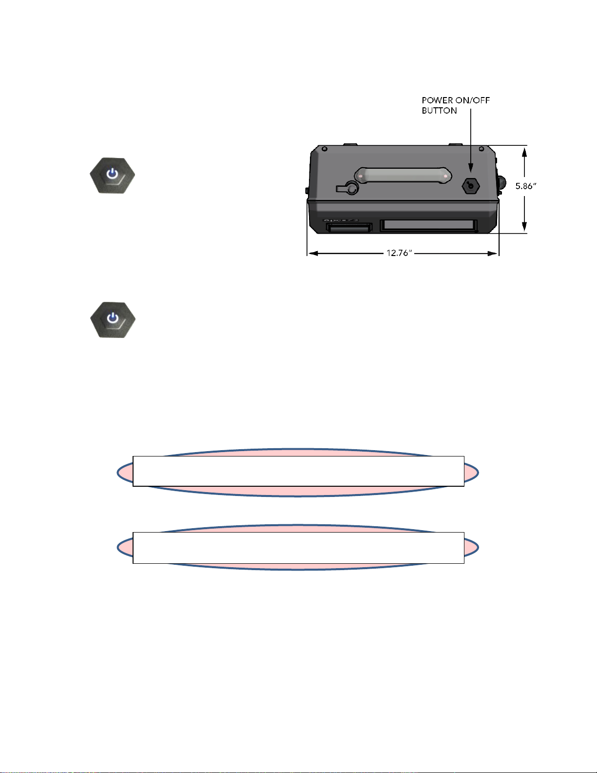
WARNING: Do not press and hold the Power button to shut down.
This will cause a hard reset and is not recommended.
WARNING: If the ApexZ is shut down during a sample,
that sample will not be completed or saved.
Power Safety
Start Up
Press the power button to turn on the ApexZ particle
counter.
Shut Down
To shut down press the power button once. DO NOT HOLD the power button down.
Users are not required to logout before ApexZ is shut down. If Users are enabled, shutting down the ApexZ will
logout the current user and will require a user to login when the ApexZ is next started. It is permissible to shut
down the ApexZ particle counter from any one of the user interface screens.
248083466-1 R6 6
Page 15

Lighthouse Worldwide Solutions ApexZ Operators Manual
WARNING: Do not attempt to sample reactive gases (such as hydrogen or oxygen) with
this instrument. Reactive gasses create an explosion hazard in the instrument. Sampling
any gas under pressure can damage the instrument and void the warranty. Sampling any
gas that is not the same density as ambient air can result in inaccurate data. Do NOT
allow water, solvents, or other liquids to enter the instrument via the inlet tube - the
instrument will be damaged and the warranty voided.
WARNING: The use of controls, adjustments or procedures other than those specified
within this manual may result in personal injury and/or damage to this instrument.
Attempts by untrained personnel to disassemble, alter, modify or adjust the electronics
or optics may result in personal injury and damage to the instrument and will void its
warranty. There are no user-serviceable components inside the particle counter. Only
factory authorized service personnel should repair or service this instrument and its
optical system. If replacement of the power supply or its AC power cord is required,
replace it only with a power supply or cord having as good as or better ratings than
specifications provided by Lighthouse Worldwide Solutions. Attempting to use an underrated power supply or cord can expose the instrument and adjacent equipment to the
user to dangerous shock and fire hazards. Failure to meet this requirement will void the
CE certification, void the instrument warranty and can result in serious personal injury.
WARNING: Electrostatic discharge (ESD) can damage or destroy electronic components.
Therefore, any service or maintenance work should be done at a static-free work station.
A static-free work station requires an ESD consultant to evaluate the work environment
and propose the equipment and apparel needed for a work station to be successful.
Sampling Safety
Operating Safety
Electrostatic Safety Information
248083466-1 R6 7
Page 16

Lighthouse Worldwide Solutions ApexZ Operators Manual
Blank Page
248083466-1 R6 8
Page 17

Lighthouse Worldwide Solutions ApexZ Operators Manual
FCC Notice
This device complies with Part 15 of the FCC Rules. Operation is subject to the following two conditions:
(1) this device may not cause harmful interference, and (2) this device must accept any interference
received, including interference that may cause undesired operation.
NOTE: This equipment has been tested and found to comply with the limits for a Class A digital device,
pursuant to Part 15 of the FCC Rules. These limits are designed to provide reasonable protection against
harmful interference when the equipment is operated in a commercial environment. This equipment
generates, uses, and can radiate radio frequency energy and, if not installed and used in accordance
with the instruction manual, may cause harmful interference to radio communications. Operation of
this equipment in a residential area is likely to cause harmful interference in which case the user will be
required to correct the interference at his expense.
NOTE: Any changes or modifications not expressly approved by Lighthouse Worldwide Solutions could
void your authority to operate this equipment.
Compliance
Class A Digital Devices
This equipment complies with FCC RF exposure limits set forth for an uncontrolled environment. This
equipment was verified for RF exposure and found to comply with FCC OET-65 RF exposure
requirements.
WARNING: Making changes to the antenna or the equipment is not permitted. Doing so may result in
the equipment exceeding the FCC RF exposure guidelines. This equipment must not be co-located or
operated in conjunction with any other antenna or radio transmitter.
248083466-1 R6 9
FCC RF Exposure Statement
Page 18

Lighthouse Worldwide Solutions ApexZ Operators Manual
CE Notice
248083466-1 R6 10
Page 19

Lighthouse Worldwide Solutions ApexZ Operators Manual
Introduction
Overview
This operating manual introduces the Lighthouse ApexZ portable particle counters ApexZ3 and ApexZ50 and
includes instructions for inspecting, installing, using and maintaining the instrument.
ApexZ3 ApexZ50
Description
The ApexZ portable particle counter comes standard with 6 particle-size channels (ApexZ3: 0.3, 0.5, 1.0, 3.0, 5.0,
10.0 microns), (ApexZ50: 0.5, 0.7, 1.0, 3.0, 5.0, 10.0 microns) and a flow rate of (ApexZ3: 1.0 CFM), (ApexZ50:
100LPM). The instrument uses a LASER diode light source and LASER beam shaping optics to illuminate a cross
section of the air flow path. As particles move along this path, they cross the LASER beam and scatter light. The
scattered light rays from particles cutting through the beam are steered to a photodiode using a system of
collection optics. The photodiode converts the image into a current which is converted to a voltage and
amplified by an electronic circuit. The amplitude of the voltage pulse is proportional to the light scattered,
which in turn is proportional to the size of the particle. The voltage pulses created by the particle are then
processed by additional electronics that analyze the height of each pulse and therefore, the size of each
corresponding particle. The result is that the number of particles of various sizes is determined. The ApexZ is
effective in both ultra-clean areas (such as ISO Class 1 or Grade A) and in more traditional clean zones rated as
ISO Class 3 or higher. Refer to Specifications in this manual for additional instrument information.
Accessories Included
ApexZ Includes: USB flash drive 512 MB with lanyard (includes ApexZ3/ApexZ5 Read Me First and Operators
Manual), ISO probe (ApexZ3: 1 CFM, ApexZ50 100 LPM), Zero count filter (ApexZ3 1 CFM fittings, ApexZ50 100
LPM fittings), 24 VDC 5.0 amp power adapter and power cord, 1 Li-Ion Smart battery included (2 battery slot
capacity), 2x rolls of printer paper, Calibration certificate, USB flash drive.
248083466-1 R6 11
Page 20

Lighthouse Worldwide Solutions ApexZ Operators Manual
Size Range
ApexZ3: 0.3 - 10.0 µm.
ApexZ50: 0.5 – 10.0 µm.
Standard 6 Channels
ApexZ3: 0.3, 0.5, 1.0, 3.0, 5.0, 10.0 µm.
ApexZ50: 0.5, 0.7, 1.0, 3.0, 5.0, 10.0 µm.
Flow rate
ApexZ3: 1.0 CFM (28.3 LPM).
ApexZ50: 100 LPM.
Laser Source
Laser Diode.
Zero Count Level
< 1 count / 5 minutes (per ISO 21501-4).
Concentration Limits
ApexZ3: 1,000,000 particles / ft3 @ 10% coincidence loss.
ApexZ50: 300,000 particles / ft3 @ 10% coincidence loss.
Counting Efficiency
ApexZ3: 50% @ 0.3 µm, 100% for particles > 1.5x first channel particle size.
ApexZ50 50% @ 0.5 µm, 100% for particles > 1.5x first channel particle size.
Calibration
Designed for ISO 21501-4 compliance.
Self-Diagnostics
Laser power/current/supply, flow out-of-range, no flow, PA background/supply/health.
Count Modes
Sample, Concentration, Beep.
Data Storage
10,000 sample records, 2500 locations, 500 Groups, 250 Pre-sets, 100 reports, 100 users.
Communication
Ethernet, Wi-Fi (802.11 b/g/n), USB key.
Supporting Software
LMS XChange 2.0
Environmental Sensors
Temperature/Relative Humidity probe: 32-122 °F (0-50 °C) ± 1 °F (0.5 °C), 15%-90% ± 2% RH.
Touch Screen Display
7.0 inch (8.89 cm), 1200 x 800 IPS color touch screen.
Speakers
2x adjustable speakers up to 70 dB to indicate status and alerts.
Carry Handle
With RGB LED’s for status and alarms.
Printer
Embedded panel-mount printer.
Reports
FED-209E, ISO-14644-1:1999, ISO-14644-1:2015 and EU GMP regulatory pass/fail reports
displayed on screen or printed.
Alert
User configurable warnings and alarms.
Sample Inlet
ApexZ3: 3/8 inch Inlet nozzle.
ApexZ50: 1/2 inch inlet nozzle.
Sample Output
Internally filtered to HEPA standard (>99.97% @ 0.3 µm); with rotatable exhaust fitting for
directed flow.
Vacuum Source
Internal blower, automatic flow control.
Enclosure
Chemically Resistant Polycarbonate blend, conductive lining, VHP compatible.
Power
External power supply: 24 VDC, 5 A max draw.
Battery
Battery Run Time
2x Li-Ion battery capacity, removable and rechargeable.
ApexZ3: 2 batteries 11 hours nominal use, 50% duty cycle no printing.
ApexZ50: 2 batteries 8 hours nominal use, 50% duty cycle no printing.
Dimensions
12.76“ (l) x 6.23” (w) x 8.88” (h), [32.41 x 15.82 x 22.55 cm].
Temperature Range
(50°F - 104°F) (10°C - 40°C), 20% - 95% relative humidity, non-condensing.
Weight
7.05 lbs. (3.19 kg) without batteries, battery weight 1.35 lbs. (0.61 kg).
Languages
English, Spanish, Portuguese, Dutch, French, Italian, Russian, Chinese, Korean, Japanese, Turkish,
Thai.
Specifications
248083466-1 R6 12
Page 21

Lighthouse Worldwide Solutions ApexZ Operators Manual
5.86”
14.88 cm
12.76”
32.41 cm
9.03”
22.93 cm
7.43”
18.87 cm
* Patent Pending
Enclosure and Ports – ApexZ3
248083466-1 R6 13
Page 22

Lighthouse Worldwide Solutions ApexZ Operators Manual
5.86”
14.88 cm
12.76”
32.41 cm
* Patent Pending
SAMPLE INLET
(0.5 INCH BARB)
*
7.43”
18.87 cm
9.03”
22.93 cm
Enclosure and Ports - ApexZ50
248083466-1 R6 14
Page 23

Lighthouse Worldwide Solutions ApexZ Operators Manual
Printer paper
tears here.
Warning: Changing the instrument language will update the instrument firmware and the
printer. It will take 1-2 minutes for the update to complete. During this time make sure the
ApexZ instrument has at least 50% battery life remaining or connected to the AC adapter and
do not turn off the instrument while updating. Failure to follow these instructions could
cause the printer to become damaged and unusable.
Printer
Load Printer Paper
Open Printer Door
Pinch the left and right
printer door tabs and
gently pull open the
printer door.
Load Printer Paper
Insert the printer
paper roll with the
paper feeding
from the back
of the roll.
Close Printer Door
Close the printer door so
that the left and right
printer door tabs snap
shut.
248083466-1 R6 15
Page 24

Lighthouse Worldwide Solutions ApexZ Operators Manual
Data Screen
Paper Feed
The printer paper feed button is located on the ApexZ Data Screen. Press the printer paper feed button to
advance the printer paper. When the report is finished printing, pull the paper gently upward and to the side to
tear the printer paper along the serrated edge of the printer enclosure.
From the Home screen press the
Data button to display the Data screen.
Advance the printer paper
Press the Paper Feed button to advance the paper
from the ApexZ embedded printer.
Tear off the printed report
Tear the printed report along the
serrated edge of the printer paper
opening.
248083466-1 R6 16
Page 25

Lighthouse Worldwide Solutions ApexZ Operators Manual
ORANGE
RED
GREEN
BLUE
LED Handle*
The ApexZ RGB LED handle lights will light up during and after a sample to indicate warning and alarm status. If
the handle LED lights are blinking then the ApexZ is currently sampling. If the handle LED light is a solid color the
ApexZ has stopped sampling. The sampling LED color that remains lit after a sample is completed indicates the
last recorded warning or alarm condition.
Blinking LED colors indicate ApexZ is actively sampling. (Blue also means alarms are disabled)
- Blinking Blue actively sampling no instrument faults, (warnings/alarms are disabled).
- Blinking Green actively sampling no instrument faults, no warnings, no alarms.
- Blinking Orange actively sampling no instrument faults, warning limit has been exceeded.
- Blinking Red actively sampling alarm limit exceeded and/or faults detected.
Solid LED color indicates ApexZ is not currently sampling.
- Solid Green sample completed no warning/alarm limits exceeded, no faults detected.
- Solid Orange sample completed warning limit exceeded, no instrument faults detected.
- Solid Red sample completed alarm limit exceeded and/or instrument faults detected.
*Patent Pending
248083466-1 R6 17
Page 26

Lighthouse Worldwide Solutions ApexZ Operators Manual
Blank Page
248083466-1 R6 18
Page 27

Lighthouse Worldwide Solutions ApexZ Operators Manual
Date & Time
User
Battery Status
Home
Screen
Data
Screen
Ethernet/Wi-Fi
Group
Location
Sample Plan
Certification
Start/Stop Sample
Press here to display the
View Options Bar
View Settings
Particle Size µm
(microns)
Data Display
(displays up to 3 columns)
Mode
Cycle #/#
Self-Diagnostics
Sample Time
# / Total Records
Sampling Status
Reports
Screen
Current Cycle
Countdown
Total Sample
Countdown
Settings
Screen
Start/Stop Zero Count
(not displayed when disabled)
Sample Settings button
USB
Alarms
Delay Time
Home Screen
Operating ApexZ
This is the Home Screen on the ApexZ airborne particle counter. Create manual or preset sample plans and
certifications for up to 2500 unique locations.
248083466-1 R6 19
Page 28

Lighthouse Worldwide Solutions ApexZ Operators Manual
Home Screen
Sample Settings Dashboard
Sample Settings Dashboard
Press the Group/Location button to
display the Sample Settings
Dashboard.
Select the manual sample button.
If no group is selected (no group
name is highlighted blue) then all
locations will display in the location
column. The first location will be
selected and highlighted blue.
Groups and Locations
Select the location to be sampled.
Edit the Sample Settings
Press the Manual Sample button to
edit the sample mode, cycles, delay,
sample time and hold time.
248083466-1 R6 20
Page 29

Lighthouse Worldwide Solutions ApexZ Operators Manual
Manual Sample - Channel/Alerts
Warning Limit
Alarm Limit
Manual Sample Settings
Manual Sample
Sample Settings
Press each sample setting button to edit:
Mode
Delay
Sample Time
Hold Time
Cycles #/#
Units ft3/m3/liters
Volume
Press the Channel/Alerts button to display
the Channel Settings screen.
Channel Settings
Press any green channel size button to
disable that channel and it will highlight
grey and strike through indicating it has
been disabled. Press again to enable that
channel.
Press any Warning or Alarm threshold
button to set those channels respective
thresholds. Select Enable or Disable.
Enter the Warning or Alarm threshold
limits respectively. Press Apply.
248083466-1 R6 21
Page 30

Lighthouse Worldwide Solutions ApexZ Operators Manual
Manual Sample - Channel/Alerts
Home Screen – Manual Sample Loaded
Save Manual Sample
Press the green Save button to display the
Home screen with the manual sample
settings.
Start Manual Sample
Press the green Start button to start
manual sampling when at the selected
location.
248083466-1 R6 22
Page 31

Lighthouse Worldwide Solutions ApexZ Operators Manual
Preset Sample Dashboard
Preset Sample Dashboard
Preset Samples
To run preset sample settings from the Home
screen press the Group/Location button to
display the Sample Settings Dashboard.
Press the Preset button and it will highlight
blue indicating that it has been selected.
All saved preset names will be displayed on
the preset name list. Select a group name and
only those locations assigned to that group
will display on the location list. If no groups
are selected then all locations will be
displayed.
Locations assigned to a preset will appear
with the link icon indicated that a preset is
currently assigned to that location.
Saved presets will display in the Preset
Name column.
Select a location with no linked preset and all
presets will be displayed.
Assign Preset to Location
Select a Preset button and it will highlight blue indicating it has been selected.
Save Preset to Location
Press the green Save button to assign the highlighted preset to the highlighted location.
248083466-1 R6 23
Page 32

Lighthouse Worldwide Solutions ApexZ Operators Manual
Location linked to Preset
Home Screen Ready to Sample
Start Preset Sampling
The selected Preset Sample Settings will be
loaded on the Home screen for the selected
location.
Press the Start button to start the sampling
preset at the selected location.
Linked Preset
If a location linked to a preset is selected then only
that preset name will be displayed on the preset
name list. A location with a linked preset cannot
be modified from the Sample Settings Dashboard.
Unlink a preset to a location
To unlink a preset from a location, return to the
Settings then Location screen and edit the Preset
selection.
248083466-1 R6 24
Page 33

Lighthouse Worldwide Solutions ApexZ Operators Manual
Sample Plan Dashboard
Home Screen
Sample Plans
To run a Sample Plan from the Home screen press the Sample Plans/Certifications button to display the
Sample Plan/Certification Dashboard.
Press the Sample Plan button and it
will highlight blue indicating that it
has been selected.
The Sample Plan Name list will display
all saved sample plans.
When no Sample Plan is selected then
all locations will be displayed and
selectable.
After a Sample Plan is selected then
only those locations assigned to that
Sample Plan will be displayed and
selectable.
248083466-1 R6 25
Page 34

Lighthouse Worldwide Solutions ApexZ Operators Manual
Selecting a Sample Plan and Location
Sample Plan 1 loaded on the Home Screen
Select a Sample Plan
Select a Sample Plan and it will
highlight blue indicating that Sample
Plan has been selected.
Locations assigned to that Sample Plan
name will display on the Location list.
Select a Location
Select the desired location to be
sampled from the Location list and
that location will highlight blue
indicating it has been selected.
Save Sample Plan
Press the Save button to load the selected Sample Plan and current Location and return to the Home screen.
248083466-1 R6 26
Page 35

Lighthouse Worldwide Solutions ApexZ Operators Manual
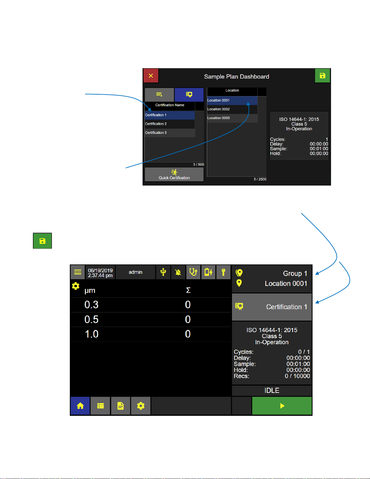
Certification Dashboard
Home Screen
Certification Sample
To run a Certification Sample from the Home screen press the Sample Plans/Certifications button to display the
Sample Plan/Certification Dashboard.
Press the Certification button and it
will highlight blue indicating it has
been selected.
The Certification Name list will display
all saved certifications. When no
certification is selected all locations
will be displayed and selectable.
After a certification is selected then
only those locations assigned to that
certification name will be displayed
and selectable.
248083466-1 R6 27
Page 36
Lighthouse Worldwide Solutions ApexZ Operators Manual
Certification Loaded on Home Screen
Selecting a Certification and Location
Select a Certification
Select a Certification name and it will
highlight blue indicating that it has
been selected.
Locations assigned to that certification
name will display on the Locations
List.
Select a Location
Select the current location to be
sampled from the locations list and
that location will highlight blue
indicating that it has been selected.
Press the green Save button to load the selected certification name and current selected location
and return to the Home screen ready to start the certification sample.
248083466-1 R6 28
Page 37

Lighthouse Worldwide Solutions ApexZ Operators Manual
Home Screen: View Options Bar Displayed
Home Screen: Data Table View
View Options
While sampling, particle count data may be viewed through multiple view options: Data Table View, Histogram
View, Sample Map View, History View, Graph View and Environmental View. From the Home screen press the
View Options button to display the View Options Menu.
Select View Option
Data Table View
Sample Map View
History View
Graph View
Environmental View
Press a view option button and the
home screen will change to that view
option and settings.
Data Table View
Press the view options gear icon to
display the data table view settings.
The data table view settings can provide
up to three columns of data that can be
displayed while sampling.
248083466-1 R6 29
Page 38

Lighthouse Worldwide Solutions ApexZ Operators Manual
Data Table View Settings
Home Screen, Data Table View 3 columns enabled
Data Table View Settings
Enable Column
Select Enable to display that column in the data
table view. Select Disable not to display that
column.
Display Counts, Warning or Alarm
Select Count to display the particle count, or
Select Warning to display particle counts
exceeding the warning threshold level, or
select Alarm to display particle counts exceeding
the alarm threshold level.
Cumulative or Differential
Select Cumulative or Differential to display either
cumulative or differential data counts.
Raw or Normalize Units
Select Raw or Norm to display data counts either Raw or Normalized
Select units of volume for normalized particle counts.
Save Data Table View Settings
Press the return icon to save the data table view settings.
The ApexZ Home screen Data View Option will
display the data specified in 3 columns.
248083466-1 R6 30
Page 39

Lighthouse Worldwide Solutions ApexZ Operators Manual
Select View Options Sample Map View
Sample Map View Screen
Sample Map View
Select the Sample Map View options
icon from the view options drop down
list.
Sample Map View displays locations
assigned to a Sample Plan or a
certification with a colored background
indicating the sampling status for that
location.
There will be no gear icon displayed on
the Sample Map View screen.
Sample Map View Location Button
Each location button will display two lines of text:
Location name
Number of samples taken / total number of sample cycles
Sample Map View allows the user to
easily select the current sampling
location by pressing the matching
location name button on the Sample
Map View screen.
When selected, the location button will
highlight with a yellow boarder color
indicating it is the current location to
be sampled.
248083466-1 R6 31
Page 40

Lighthouse Worldwide Solutions ApexZ Operators Manual
Home Screen – Sample Map View
Home Screen – Sample Map View
Identify your monitoring point location
and select that location on the Sample
Map View screen by pressing that
location name button. The selected
location button will highlight with a
yellow boarder and the Start button will
highlight green indicating the ApexZ
instrument is ready to sample at the
current location. Make sure your sample
tube and sample probe are in place at
the selected location point.
Press the green start button to start
sampling at the current selected
location.
After sampling completes then move the ApexZ to the next monitoring point. Make sure your sample tube and
probe are in place at the new location and then select the matching current location on the Sample Map View
screen. Press the green start button to start sampling at the new location.
Location Color Status
Yellow boarder = current location
Green back ground = sample completed
with no warning or alarms exceeded.
Blue back ground = currently sampling.
Note if a sample has multiple cycles then
the back ground color will change after
the first cycle is completed if the particle
count exceeds the warning or alarm
thresholds or the sensor goes into fault.
Grey back ground = location not sampled
Orange back ground = sample completed
at that location and the warning threshold particle count was exceeded.
Red back ground = sample completed and the alarm threshold particle count was exceeded at that location.
Note a red back ground color will also display if the instrument was in fault for its laser, flow or calibration due
date.
248083466-1 R6 32
Page 41

Lighthouse Worldwide Solutions ApexZ Operators Manual
Home Screen – Sample Map View
Sample Map View Sample Data Display
To view data counts while sampling from
Sample Map View, press the location button
that is currently sampling and highlighted blue.
Data counts (from the first two columns of the
Data View Settings) will display in a pop up
window with white text against a blue
background.
When a Sample Plan is running the user will be prompted to start each sample at each location. The user may
select any of the available locations from that Sample Plan to be the next location. When the desired next
location has been selected and the sample probe is at the matching location, the user may press Start to begin
sampling at that location.
248083466-1 R6 33
Page 42

Lighthouse Worldwide Solutions ApexZ Operators Manual
Select Histogram View Option
Note: Histogram View displays real time particle count data as a Histogram.
Histogram View Settings
Histogram View Screen
Histogram View
From the Home Screen press the
View Options button then press
the Histogram View button.
Press the gear icon to display the
Histogram View Settings.
Histogram View Settings
Select Linear or Logarithmic.
Select Cumulative (Σ) or the Differential (Δ).
Select Raw or Normalized with units of volume.
If Normalized is selected then select units; cubic feet, cubic meters or liters.
Press the back arrow button to apply the settings and return to the
Histogram View.
248083466-1 R6 34
Page 43

Lighthouse Worldwide Solutions ApexZ Operators Manual
Selecting Graph View Option
Graph View Screen
Graph Settings
Graph View
Press the View Options button.
Then press the Graph View button.
Graph View displays sampled data points
continuously in real time on a line graph. A new
line graph will begin when sampling is stopped and
restarted.
Press the Graph View gear button to display
the Graph Settings.
Graph View Settings
Select Linear or Logarithmic
Select Channel size
Select Format Raw or Normalized with units ft3, m3, L.
Press the back button to return to the Graph View
screen.
248083466-1 R6 35
Page 44
Lighthouse Worldwide Solutions ApexZ Operators Manual
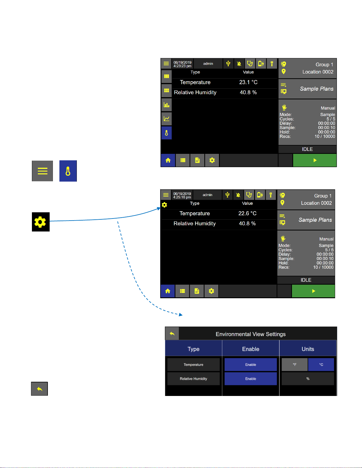
Environmental View Screen
Environmental View Settings Screen
Select Environmental View Option
Environmental View
ApexZ can sample and collect temperature
and humidity data readings while counting
particles during a sample session.
Connect an ApexZ Temperature / Humidity
probe and view temperature and humidity
data while sampling in real time from the
Environmental View Option screen.
From the Home Screen press the View
Options button. Then press the
Environmental View button.
Press the gear button to display the
Environmental View Settings Screen
Environmental View Settings
Press the enable button and it will highlight blue
indicating the sensor type has been enabled.
Press Units for °F or °C.
Relative Humidity will be displayed as %.
Press the Back button to return to the
Home page Environmental View.
248083466-1 R6 36
Page 45

Lighthouse Worldwide Solutions ApexZ Operators Manual
Data Screen
Data screen displaying channel columns expanded
Data Screen
View Data Records
The ApexZ can store up to 10,000 sample data records and display them on the data screen. The user can scroll
up and down, left and right and view all saved data records. Individual or multiple data records can be selected
and a Tag Name can be created and saved in the data record.
Data field columns
The Data screen will display data columns
for the date/time stamp, sample name,
group, location, particle counts by channel
size, analog data values, tag, username,
alerts and faults will all be displayed on
the data screen.
Additional columns can be viewed by
clicking on the column expansion arrow
buttons to the right of each column
heading.
Channels column expanded
Press the right arrow button to expand
and the left arrow button to collapse the
channel columns.
Slide the horizontal scroll bar or press the
right and left arrows to view additional
data columns.
Slide the vertical scroll bar or click on the
arrows up and down to scroll through
data records saved on the ApexZ.
248083466-1 R6 37
Page 46

Lighthouse Worldwide Solutions ApexZ Operators Manual
Note: Swipe the screen or slide the Elevator Bars to
view additional columns to the right or left.
Analogue Columns Expanded
Alert and Fault Columns Expanded
Data Screen – Data Columns
Analog columns expanded
Press the right arrow button to expand and the left arrow button to collapse the data columns.
Use the horizontal scroll bar to view additional data columns to the right or swipe your finger on screen to scroll
up or across and display additional rows and columns.
248083466-1 R6 38
Page 47

Lighthouse Worldwide Solutions ApexZ Operators Manual
Data Screen
Data records selected
Status Bar
Viewing: #/#
Filtered data records / total data records.
Selected: #
This represents total data records currently
selected / highlighted blue.
Data buffer: #/10,000
This represents total # of saved data records /
total capacity (10,000 records).
Select Data Records
Press anywhere on a data record row and that
data record will highlight blue indicating it is
currently selected. Press additional rows and
they will highlight blue indicating they are also
selected now as a group.
To unselect press again and the data record will
return to grey/dark grey highlight indicating the
data record is no longer selected.
248083466-1 R6 39
Page 48

Lighthouse Worldwide Solutions ApexZ Operators Manual
Data Screen
Enter Tag Name Screen
Tag data records
Tags can be used to add batch names or numbers, short notes, or notations to a single data record or a selected
group of data records.
Select Data Records
Select a single data record or a group of data
records and they will highlight blue indicating
these records are currently selected.
Press the Tag button to display the Enter Tag
Name Screen.
Tag Name
Enter the Tag Name using the keypad.
The tag name can be up to 64 characters long.
Press Apply to save the Tag Name
to the data record(s) selected.
248083466-1 R6 40
Page 49

Lighthouse Worldwide Solutions ApexZ Operators Manual
Data Screen
Export Type Screen
Note: If the USB button is grey or disabled,
attach a USB key to the ApexZ USB port.
Export Data Records
Data records on the ApexZ can be output to the printer, a USB key or a CIFS (Common Internet File System).
Data exported to a USB and CIFS will be saved as a .csv, .lsdx, or .pdf file.
Select Data Records
Select a single data record or a group of data
records.
Press the Export button to display the Export Screen.
Select Export Type
Select the Export Type: Printer, USB or CIFS buttons.
The selected output type button will highlight green.
Press the save button to start the Export.
248083466-1 R6 41
Page 50

Lighthouse Worldwide Solutions ApexZ Operators Manual
Data Screen
Note: Selecting data records from a filtered display of data records will not filter
the data set included in the generated report. All data records from the oldest
to the newest data record set selected will be included in the generated report.
Make Report from Data Records
Reports may be created from selecting a continuous set of data records from the Data Screen and then pressing
the Create New Report button. The user will be asked to set report sample parameters and then create a new
Report based on the selected data record samples collected. Follow these steps to select the data records,
report type, channels; enter a new report name and save the report.
Select Data Records for Report
Press and highlight the desired data records to
make a Report.
Press the + Report button to display
the New Report screen.
248083466-1 R6 42
Page 51

Lighthouse Worldwide Solutions ApexZ Operators Manual
New Report Channels
New Report Type
Report Type
Press the Type button.
Select the Report Type:
ISO 14644-1: 2015
EU GMP
ISO 14644-1: 1999
FED 209E (Federal Standard 209E)
Press the Channel button next to
display the Report Channels Screen.
Report Channels
ApexZ will enable the required channels and
will set the target limits for the chosen
report type standard.
Enabled channels will display with a green
check box.
Disabled channels will be displayed with the
null symbol, a circle with a line through it.
These particle channel sizes are not within
the certification standard and may not be
enabled.
Press the Name button to display the Report
Name Screen.
248083466-1 R6 43
Page 52
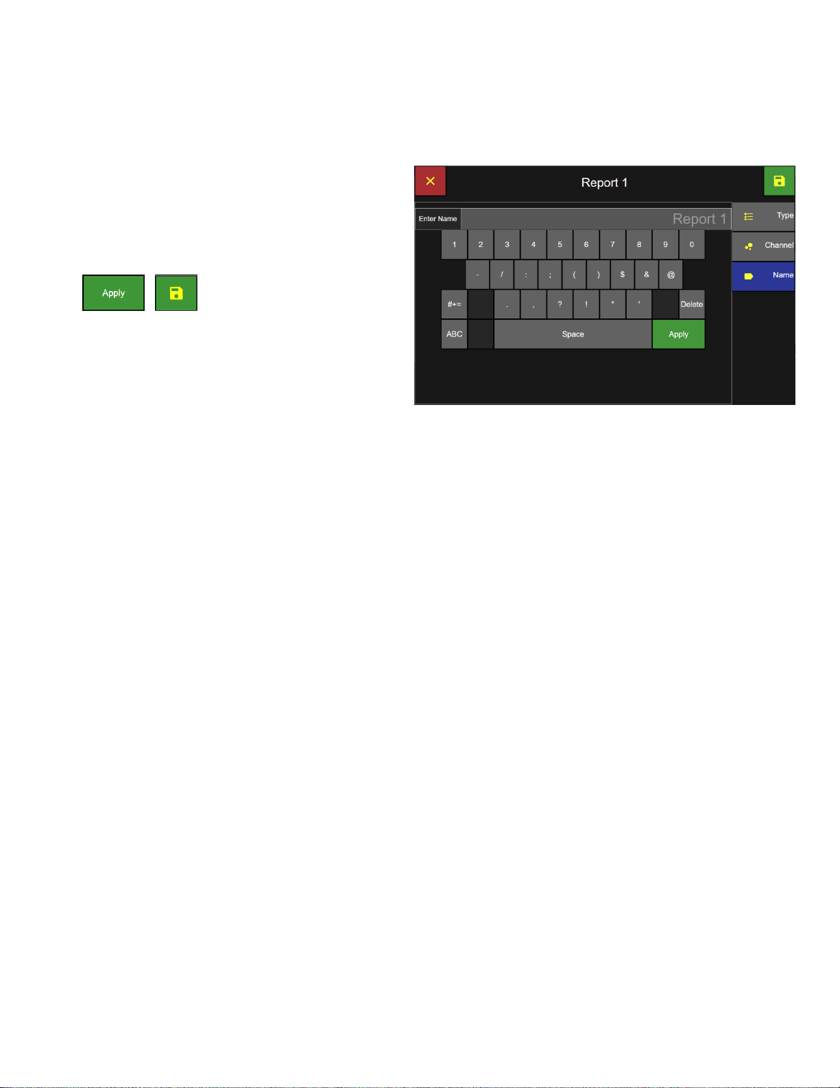
Lighthouse Worldwide Solutions ApexZ Operators Manual
Report Name Screen
Report Name
Enter the Report Name from the keyboard.
Press the green Apply button to apply report name.
Press the green Save button to save the
report and return to the Data Screen.
The new report name will be saved on the Report
screen.
248083466-1 R6 44
Page 53

Lighthouse Worldwide Solutions ApexZ Operators Manual
Data Screen
Filter Data – Date Keypad
Filter Data – Time Keypad
Filter Data Records
From the Data Screen:
Press the Time button to display the
Date & Time Screen Filter
Filter Start date and time
Press the Start Date button and select the starting
day, month and year for the filter period using the
keypad.
Press the Start Time button and enter the start time
on the keypad.
Filter End date and time
Press the End Date button and enter the end date
on the keypad.
Press the End Time button and enter the end time
on the keypad.
Press the green Apply button and press the green
Save button to apply the Date and Time filter to the
data records on the Data Screen.
248083466-1 R6 45
Page 54

Lighthouse Worldwide Solutions ApexZ Operators Manual
Group Filter
Data Screen
Filter Groups
Press the Group button to
display the Filter Group Screen.
Select Group to Filter
Select the Group name(s) to be included
in the data records filter and press the
adjacent include button. The button will
highlight green with a check mark
indicating the group name has been
included in the filter.
Press the include button a second time to
remove selection. A grey back ground
color indicates no filter on this parameter.
Press the green Save button to save the
filter settings and return to the Data
Screen.
248083466-1 R6 46
Page 55

Lighthouse Worldwide Solutions ApexZ Operators Manual
Location Filter
Data Screen
Filter Locations
Press the Location button to
display the Filter Location Screen.
Select the Include button next to the
Location name(s) to be included in the
data records filter.
The button will highlight green with a
check mark indicating it will be included
in the data record filter.
Press the green Save button to save the
Location filter and return to the Data
Screen.
248083466-1 R6 47
Page 56

Lighthouse Worldwide Solutions ApexZ Operators Manual
Filter Sample Plans and Certifications
Data Screen
Filter Sample Plans and Certifications
Press the Sample Plan button to
display the Filter Sample Plans screen.
Press the Include button next to the
Sample Plan or Certifications to be
included in the data records filter.
The button will highlight green with a
check mark i4ndicating it will be
included in the data record filter.
Press the green Save button to activate
the filter settings and return to the Data
Screen.
248083466-1 R6 48
Page 57

Lighthouse Worldwide Solutions ApexZ Operators Manual
Filter Tags
Data Screen
Filter Tags
Press the Tag button to display the Filter
Tag screen.
Select the Include button next to the Tag
name(s) to be included in the data
records filter.
The button will highlight green with a
check mark indicating it will be included
in the data record filter.
Press the green Save button to activate
the filter settings and return to the Data
Screen.
248083466-1 R6 49
Page 58

Lighthouse Worldwide Solutions ApexZ Operators Manual
Data Screen
Note: Press the Reset Filter button to disable all included filters.
Filter Alert / Fault
Filter Alert/Fault
Press the Alert/Fault button to
display the Alert/Fault Screen.
Select the Include button next to the
Alert/Fault(s) to be included in the data
records filter.
The button will highlight green with a
check mark indicating it will be included
in the data record filter.
Press the green Save button to activate
the filter settings and return to the Data
Screen.
248083466-1 R6 50
Page 59

Lighthouse Worldwide Solutions ApexZ Operators Manual
Note: ApexZ can only delete all records. There is
no option to delete individual records.
Data Screen
Confirm Data Records Delete
Delete all data records
ApexZ will store up to 10,000 sample data
records and after the database is full then
the newest data records will copy over the
oldest data records wrapping the database.
Data records may not be deleted
individually.
To delete All data records press
the trash can button to display
the Data Records Delete Screen.
Press green check mark button to delete ALL data records.
Or press the red x button to cancel and data records will NOT be
deleted.
248083466-1 R6 51
Page 60

Lighthouse Worldwide Solutions ApexZ Operators Manual
Blank Page
248083466-1 R6 52
Page 61

Lighthouse Worldwide Solutions ApexZ Operators Manual
Reports Screen
Result Columns Expanded
Reports
Report Screen
The Reports screen displays a list of all saved certification reports.
Reports that have Passed their certification conditions will be highlighted green and display “PASS” in the
Results column. Reports that have failed their certification conditions will be highlighted red and display “FAIL”,
indicating they have failed.
From the Home Screen select the Report icon
button to display the Report screen.
Expand Result Columns
Press the arrow button to expand the Result
columns.
Use the horizontal slider button or arrow
buttons to display more columns to the right or
left.
248083466-1 R6 53
Page 62

Lighthouse Worldwide Solutions ApexZ Operators Manual
Report data columns displayed include date created, report name, and fault results for over limit data counts,
minimum sample volume not met, minimum samples not taken, minimum sample time not sampled, and
instrument fault.
Report Result Column Expanded
Over Limit, Minimum Volume, Minimum Locations, Minimum Samples, Min. Sample Time, Instrument Fault
248083466-1 R6 54
Page 63

Lighthouse Worldwide Solutions ApexZ Operators Manual
Reports Screen
Select date, month and year.
Select Time
Filter Report List
The list of reports displayed on the Reports
screen can be filtered by the date the report
was created, the report type or the report
pass/fail status.
Filter report date and time
From the Reports Screen press the Created
button to go to the Filter Created Screen
Select the Start/End date button and the date keypad
will be available to enter the start/end dates for the
desired data records filter.
Select the Start time and End time buttons and use the Time keypad to enter the report
filter start and end times. Select am/pm. Press the Apply button.
Press the Save button to return to the Reports screen.
248083466-1 R6 55
Page 64

Lighthouse Worldwide Solutions ApexZ Operators Manual
Note: Press the Reset Filter button to disable all included filters.
Select Certification Type Filter
Select Pass/Fail Filter
Filter Certification Type
Select the Include button next to the
certification Type(s) to be included in the
filter. The include button will highlight green
with a yellow check mark indicating that
certification Type is included in the data
records filter.
Press the Save button to apply the filter and
return to the Reports screen.
Filter Pass/Fail
Select the Include button next to the
Pass/Fail Type(s) to be included in the filter;
Cannot Classify, Fail or Pass.
The include button(s) will highlight green
with a yellow check mark indicating that
type is included in the Report list filter.
Press the include button a second time and
the button will change to a grey color
indicating it is not included in the data
records filter.
Press the green Save button to apply the
filters and return to the Reports Screen.
If you do not press the Save button then no new filters will be applied. If you press the red x button to
cancel then also no filters will be applied. If no Types are included then no filters will be applied and
all Reports will be displayed on the Reports screen.
248083466-1 R6 56
Page 65

Lighthouse Worldwide Solutions ApexZ Operators Manual
Select Report to Export
Export Output
Export Report
Select a report to export and it will highlight
blue indicating it has been selected.
Press the Export button.
Select the Export type output to Printer, USB (.pdf) or CIFS (.pdf).
Press the Confirm Export button to start the export.
Preparing Data will count up from 0 to 100%
USB Export will count up from 0 to 100%
248083466-1 R6 57
Page 66

Lighthouse Worldwide Solutions ApexZ Operators Manual
Select Report to Delete
Confirm Report to Delete
Delete a Report
Select a report to delete and it will highlight blue
indicating the Report has been selected.
Press the Delete Report button to display the
Delete report confirmation screen.
Press the green check box to delete the named Report.
Or press the red x box to cancel with no report deleted.
248083466-1 R6 58
Page 67

Lighthouse Worldwide Solutions ApexZ Operators Manual
Audit Trail Screen
Export Audit Trail
Audit Trail
The Audit Trail Screen creates a timestamp and message for every user action and data record recorded on the
ApexZ instrument. Every time a sample is recorded or a user changes a current setting or modifies a
configuration parameter; a timestamped message will be recorded in the Audit Trail. After 20,000 records have
been recorded in the audit trail the next record will replace the oldest record.
Press the Reports Screen Button
From the Home screen press the Reports button
and then press the Audit Trail button to display
the Audit Trail Screen.
Press the arrow button or slide the scroll bar up
and down to view the audit trial history.
Export Audit Trail to USB or Network drive
Press the Export button to export the Audit Trail.
Select export to USB or Network.
Press the Export button.
If a USB key is inserted then a pop up message will display saying “Preparing
Data” and “USB Export” each will count up from 0 to 100%.
The USB file will be saved on the USB key in .CSV format and named:
Audit_YYMMDD_HHMMSS_ApexName.csv
248083466-1 R6 59
Page 68

Lighthouse Worldwide Solutions ApexZ Operators Manual
Blank Page
248083466-1 R6 60
Page 69

Lighthouse Worldwide Solutions ApexZ Operators Manual
Settings
Locations and Groups Screen
Settings
Settings are used to create locations, groups, presets, sample plans and certifications. In addition instrument
settings, connectivity, users and service are managed from the Settings screens.
The Settings gear button will only be available to “Admin” and “Power User” level logins. When an “Operator”
level username is logged in the Settings gear button will be disabled and the operator logged in will not have
access to any of the settings screens. If Users are disabled then the settings button and screens will be active
and accessible to anyone.
From the Home screen press the Settings gear icon to display the settings screen button list for Location, Preset,
Sample Plans, Certifications, Users, Connectivity, Instrument and Service.
Select a settings button from the right column and that settings screen will highlight blue to indicate it has been
selected and is being displayed. In the example below the Location button is highlighted blue and the Location
screen is displayed.
248083466-1 R6 61
Page 70

Lighthouse Worldwide Solutions ApexZ Operators Manual
Blank Page
248083466-1 R6 62
Page 71

Lighthouse Worldwide Solutions ApexZ Operators Manual
Settings: Groups and Locations
Note: If Users are enabled
then Settings will NOT be
available to users logged in
with Operator level access.
Home Screen
Note: The Settings Screen
defaults to the Location
button selected and the
Groups and Locations
screen displayed.
Instrument Settings
Time & Date
The Instrument Settings screen allows the user to view and edit options and settings for date/time, audio/visual,
global channels, warning/alarm data count format and units, sample and zero count settings, data output and
formatting, saving and loading configurations files.
Access the Settings Screen
From the Home screen press the gear icon to
display the settings screen.
Access Instrument Settings
From the Settings screen press the Instrument
button to display the Instrument Settings
screen.
248083466-1 R6 63
Page 72

Lighthouse Worldwide Solutions ApexZ Operators Manual
Instrument Settings Screen
Pick Date (month/day)
Pick Date (year/month)
Press the Time button to edit the
date, date format, time zone, time
and time format.
Set Current Date
Press the Date button to display the
Pick Date screens
Select today’s day, month and year.
Select the green save button to save the date settings.
Or press the red x button to cancel.
248083466-1 R6 64
Page 73

Lighthouse Worldwide Solutions ApexZ Operators Manual
Select Date Format screen
Instrument Settings: Date and Time
Set Date Format
Select the Date Format button
to display the Select Date Format screen.
Select Date Format
MM/dd/yyyy
DD/MM/yyyy
yyyy-MM-dd
Press the green save button to save the date format setting.
248083466-1 R6 65
Page 74

Lighthouse Worldwide Solutions ApexZ Operators Manual
Instrument Settings: Time Screen
Select Time Zone screen
Click and drag
the scroll bar
to scroll up and
down the Time
Zone List.
Or click on the
arrow to scroll.
Set Time Zone
Press the Time Zone button
to display the Select Time Zone
screen.
Press and select your UTC-Time Zone.
Press the green save button to save the
UTC-Time Zone.
248083466-1 R6 66
Page 75

Lighthouse Worldwide Solutions ApexZ Operators Manual
Instrument Settings: Date and Time Screen
Enter Time keypad
Instrument Settings: Time Format
Note: If 24 HR time format is selected
then no am/pm will be displayed.
Set Current Time
Press the Time input button to display the Enter
Time keypad.
Enter the current time from the numeric keypad as HH:MM:SS
Select am or pm from the toggle button.
Press the green Apply button to save the current time entered.
Set Time Format
Press the Time Format button to toggle
between 12 or 24 hour time format.
248083466-1 R6 67
Page 76

Lighthouse Worldwide Solutions ApexZ Operators Manual
Instrument Audio/Visual Screen
Select Digital Grouping Screen
Note: Enabled Alarms will always sound at 100%.
Select Decimal Mark Screen
Select Language Screen
Warning: Changing the instrument language will update the instrument firmware and the
printer. It will take 1-2 minutes for the update to complete. During this time make sure the
ApexZ instrument has at least 50% battery life remaining or connected to the AC adapter and
do not turn off the instrument while updating. Failure to follow these instructions could
cause the printer to become damaged and unusable.
Audio/Visual
Volume
Touch and slide the volume button from 0 – 100%.
Brightness
Touch and slide the brightness button 0 – 100%.
Language
Press the Language button to display the Select Language screen.
Select the desired language.
Press the green save button.
Decimal Mark
Press the Decimal Mark button to display the
Select Decimal Mark screen.
Select period or comma.
Then press the green save button.
Digit Grouping
Press the Digit Grouping button to display the
Select Digit Separator screen.
Select none, space, comma or period.
Then press the green save button.
248083466-1 R6 68
Page 77

Lighthouse Worldwide Solutions ApexZ Operators Manual
Instrument Options
Enabled
Disabled
Global Channels
Global Channels
Options
Global Channel Options
ApexZ can lock specific particle size channels globally for Presets and Sample Plans. For example the user can
lock channels 0.5 and 5.0 and then for all new sample plans or presets only those two channels will be sampled
and the particles counted. Certifications are not affected by Global Channels enabled. Certifications will always
use the channel sizes required from the certification standard.
Click to enable the Lock Global Channels button
and then click on the Global Channels buttons to
display the edit Global Channels pop up screen.
Press on any one of the global channel buttons to
display the Global Channels screen.
Press any channel button to disable it.
Press the green save button to save the global channel settings.
248083466-1 R6 69
Page 78

Lighthouse Worldwide Solutions ApexZ Operators Manual
Global Channels
Tool Tips: Connectivity AD/LDAP
Tool Tips: Lock Global Channels
When Lock Global Channels are enabled then only
those channels enabled and highlighted green will be
sampled.
Warning/Alarm
Select either Raw or Norm (normalized) for the
particle count warning and alarm limits.
Raw = total particles counted.
Norm = Normalized counts per unit of measure.
Select Normalized units: ft3/m3/L.
Tool Tips
Tool tips are included within Connectivity AD/LDAP,
CIFS and Instrument Options, Output &
Configuration screens.
Click on the icon or label of the option or setting and
a brief description of what that feature does will
appear.
248083466-1 R6 70
Page 79

Lighthouse Worldwide Solutions ApexZ Operators Manual
Instrument Options Enable Users
Home Screen - Auto Locked
Note: All buttons disabled during auto lock.
User Options
Enable Users (enable/disable)
Press the Enable Users button and go
directly to the Login Screen.
Enable Guest Account (enable/disable)
Press to enable guest account and then a
guest user will be permitted to login
without a password and will be assigned a
“user” level access.
Auto Lock (enable/disable)
Press to enable Auto Lock and
automatically lock the screen after the
timeout period.
Timeout
Enter the timeout period to lock the screen
when auto lock is enabled.
Include Sample Time (enable/disable)
If Include Sample Time is enabled then the timeout timer will countdown during idle screen time or while
sampling. If “Include Sample Time” is disabled then the timeout timer will not count down during a sampling
session.
Unlock screen from Auto Lock
Press the User Button to unlock user screen.
Then select
- Switch User (new login required)
- Unlock (password required)
- Cancel (remain locked)
248083466-1 R6 71
Page 80

Lighthouse Worldwide Solutions ApexZ Operators Manual
Instrument Options: Sample
Zero Count Mode
Sample Options
Pump Startup
When Pump Startup Disabled: The ApexZ pump will start up after the sample Delay time has expired.
When Pump Startup Enabled: The ApexZ pump will start immediately after pressing the sample Start button.
Disable User Sample Stop
When Enabled, “Disable User Sample Stop”
will not allow a sample that has been started
to be stopped. When Disabled, any sample
may be stopped at any time.
Zero Count Options
Mode: Press the Zero Count Mode button to select one of the following
3 modes.
Disabled: The zero count button will be inactive and will not display.
Manual: Zero count button will display and run for the sample
time when pressed.
Auto: In Auto mode, zero counting will be successful after sustaining a
6 second rolling average particle count = 0 for the duration of the zero
count sample time period.
Then press the green save button.
248083466-1 R6 72
Page 81
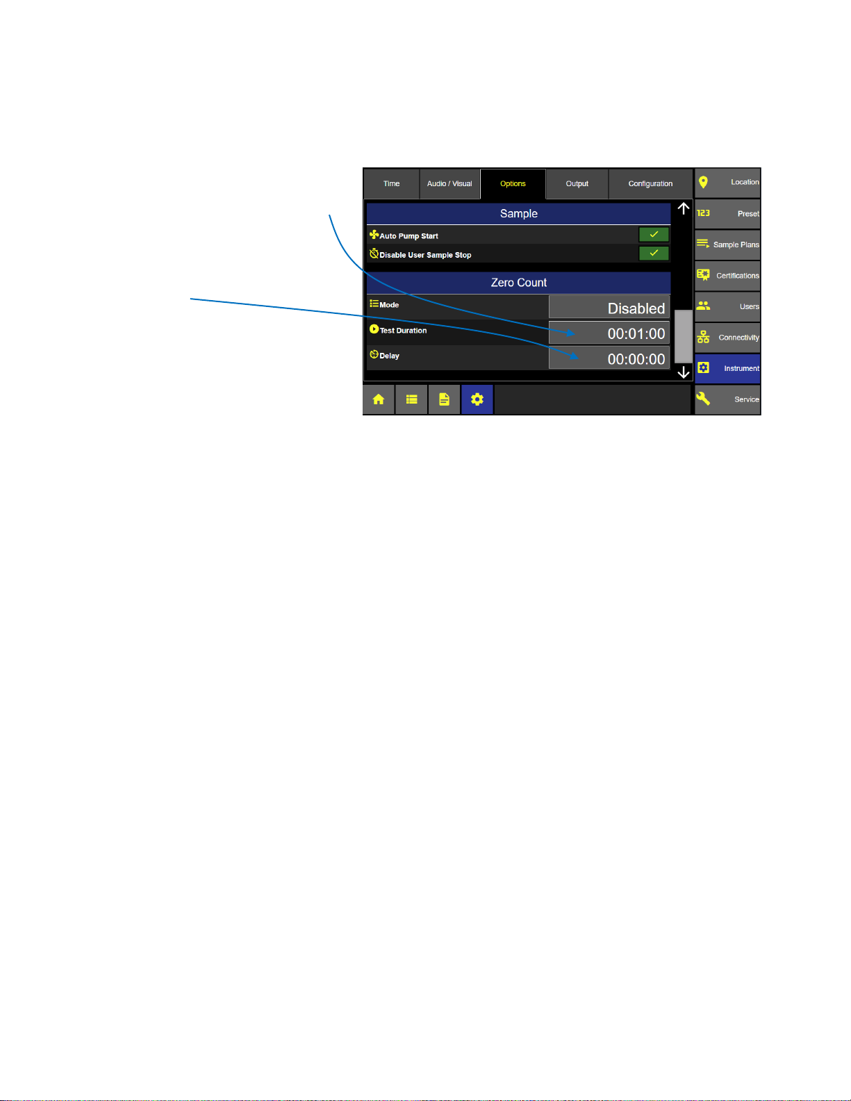
Lighthouse Worldwide Solutions ApexZ Operators Manual
Instrument Options: Zero Count
Test Duration
Press the Test Duration button to enter
your desired zero count sample time with
the pop up numeric keypad.
Delay Time
Press the delay button to enter the desired
delay time.
Delay Time will start after pressing the zero
count start button on the Home screen.
The Zero Count Sample time will start
immediately after the delay time is
completed.
248083466-1 R6 73
Page 82

Lighthouse Worldwide Solutions ApexZ Operators Manual
Instrument Options: Output
Instrument Options Output
Output
The Output screen allows the user to adjust output settings and data formatting for USB, Print, CIFS in addition
to Save and Load Configuration.
USB
Press the USB button to display the Data Output
and Formatting.
File Format
Set the file format to .csv, .lsdx or .pdf.
Data and reports output to USB will be saved in
the selected format.
On Sample (.csv format only)
Enable Output “On Sample” and output will
initiate after every sample.
On Alarm (.csv format only)
Enable Output “On Alarm” and output will initiate after every alarm is exceeded.
Raw / Norm (Normalized)
Select either Raw data counts, Normalized data counts. If you select Norm you will be prompted to select
normalize units either cubic feet, cubic meters or Liters.
Print
On Sample
Enable Output “On Sample” and output will print
after every sample is completed.
Average
Enable Average to print the average counts of all
cycles at a given location after all cycles have
completed.
On Alarm
Enable Output “On Alarm” and output will print
after every alarm is exceeded.
Reverse
Select Reverse and printing will print from the bottom up.
Font Size
Select Large or Small font size for print output.
248083466-1 R6 74
Page 83

Lighthouse Worldwide Solutions ApexZ Operators Manual
Instrument Output Print Data
Instrument Output Print Statistics
Instrument Output Print Formatting
Print Data
Select to print data either Cumulative,
Differential or both.
Select to print Raw or Normalized data
with normalized units.
Print Statistics
Enable or disable statistics to print:
Mean
Minimum
Maximum
Std. Dev.
Std. Error
95% UCL
Enabled parameters will print on the output.
Print – Formatting
Select to enable print formatting for:
Model
Serial #
CalDate (calibration due date)
User Name
Tag
Separator
Company
Address
Enabled parameters will print on the output.
248083466-1 R6 75
Page 84

Lighthouse Worldwide Solutions ApexZ Operators Manual
Instrument Output CIFS
CIFS
Common Internet File System
Select the CIFS button.
File Format
Select either .csv, .lsdx (Lighthouse Secure Data Transfer), or .pdf. Outputs to CIFS will be saved in the
highlighted format.
Include Audio Trail
Select Include Audit Trail and all audit trail records will be included in the output.
Clear Data Buffer
Select Clear Data Buffer and after the data file has been successfully copied to the CIFS share then the ApexZ
instrument database will be cleared. If the data exporting fails then the ApexZ database will not be cleared.
Formatting
Select Data Format as Raw, Normalized or both. When selecting Normalized also select the Normalize Units
(cubic feet, cubic meters or Liters). When selecting both Raw and Normalized then output to .csv file format is
required.
248083466-1 R6 76
Page 85

Lighthouse Worldwide Solutions ApexZ Operators Manual
Instrument Options: Configuration
Save Configuration File
Configuration
All of the ApexZ settings are saved in the ApexZ configuration file and can
be exported onto a USB key. The exported configuration file can then be
loaded onto another ApexZ instrument or edited using our LMS XChange
software.
Save ApexZ configuration file to USB key
Place a USB key in the ApexZ USB drive.
Press the Save button to display the Save Confirmation screen.
Press the green check mark button to confirm exporting the configuration to
the USB key.
Or press the red x button to cancel.
248083466-1 R6 77
Page 86

Lighthouse Worldwide Solutions ApexZ Operators Manual
WARNING: Importing a configuration will remove
the current configuration, and you will be taken
back to the home screen.
Select Configuration File to Load
Confirm to load configuration
Load ApexZ configuration file from a USB key
Place a USB key with the desired configuration file in
the ApexZ USB drive and press the Load button.
The Select File screen will display next.
Select your configuration file to load and it will highlight blue.
Press the Save button to load the selected configuration.
Press the green check button to import configuration.
Or press the red x button to cancel with no import.
248083466-1 R6 78
Page 87

Lighthouse Worldwide Solutions ApexZ Operators Manual
Connectivity
Connectivity
From the Settings screen press the Connectivity button to view Ethernet, WiFi, AD/LDAP, CIFS and 3rd Party API
settings.
LMS XChange Software 2.0
The LMS XChange 2.0 software was designed for use with ApexZ particle counters and is downloadable from the
www.golighthouse.com website. LMS XChange 2.0 allows users to import data collected on ApexZ3 and
ApexZ50 portable particle counters and display the data in a table that the user can view and/or save to an Excel
or PDF file. Additionally, Administrator users can manage configurations for ApexZ instruments using LMS
XChange. LMS XChange has the following main features:
• Import data manually from Lighthouse ApexZ3 and ApexZ50 particle counters.
• Import .lsdx (Lighthouse secure data transfer) files created by ApexZ3 and ApexZ50 instruments.
• Display the imported data in a table, allowing the user to also export the data to an Excel or PDF file.
• Three levels of user accounts – Operators, Power Users, and Administrative users.
• LMS XChange Administrator users can create, edit, save and load ApexZ3 and ApexZ50 configurations.
• Record logins, updates, delete, import, configuration changes, etc. in the LMS XChange Audit Log.
248083466-1 R6 79
Page 88

Lighthouse Worldwide Solutions ApexZ Operators Manual
Connectivity: Ethernet Enabled
Connectivity: Ethernet Disabled
Ethernet
When Ethernet is enabled, the IP Address,
Subnet and Gateway will be locked out from
editing.
Ethernet is enabled:
IP, Subnet, Gateway are LOCKED.
DHCP is enabled:
Ethernet Disabled
Disable the Ethernet and disable DHCP to
allow editing of the IP Address, Subnet and
Gateway.
Ethernet and DHCP disabled.
IP Address, Subnet, Gateway are available
to edit.
DHCP is disabled.
248083466-1 R6 80
Page 89

Lighthouse Worldwide Solutions ApexZ Operators Manual
Subnet Address
IP Address
Gateway Address
Note: MAC Address is fixed and unique
to the ApexZ instrument and cannot be
changed.
Connectivity: Ethernet
Edit Ethernet Address
Press the IP address, subnet or
gateway input buttons to display the
input key pad and edit these values.
Enter the valid Address and press the Apply button.
When IP, Subnet and Gateway are entered then press the Enable button to enable the Ethernet connection
248083466-1 R6 81
Page 90

Lighthouse Worldwide Solutions ApexZ Operators Manual
Connectivity: Ethernet with DHCP Enabled
Connectivity: DHCP enabled
DHCP
(Dynamic Host Configuration Protocol)
When DHCP is enabled the IP Address,
Subnet and Gateway will be dynamically
assigned from the HOST network
connection.
User editing will be locked.
To enable DHCP, disable the Ethernet
connection first.
After the DHCP has been enabled press
the Enable Ethernet button to complete
the DHCP connection.
.
248083466-1 R6 82
Page 91

Lighthouse Worldwide Solutions ApexZ Operators Manual
Scan for Wi-Fi
Connectivity: Wi-Fi Screen
WIFI 1
Enterprise Wi-Fi
Wi-Fi – No Security
Manual
Open Wi-Fi configurations:
Security will be preset to “None”.
Enterprise Wi-Fi configurations:
Security will be preset to WPA-EAP.
Server Certificates are accepted but not required.
Username input is required.
Password input is required.
Local Network Wi-Fi:
Security will be preset to WPA-PSK.
Password input is required.
Wi-Fi
Press the Wi-Fi Enable button to enable Wi-Fi.
Press the + button to Configure one to five Wi-Fi
connections.
Press the Scan button to search for available
Wi-Fi networks or routers in the area.
Press and select a Wi-Fi network
for your ApexZ communication.
After a Wi-Fi has been selected ApexZ will mark
with a red dot the remaining required tabs to
complete the configuration.
248083466-1 R6 83
Page 92
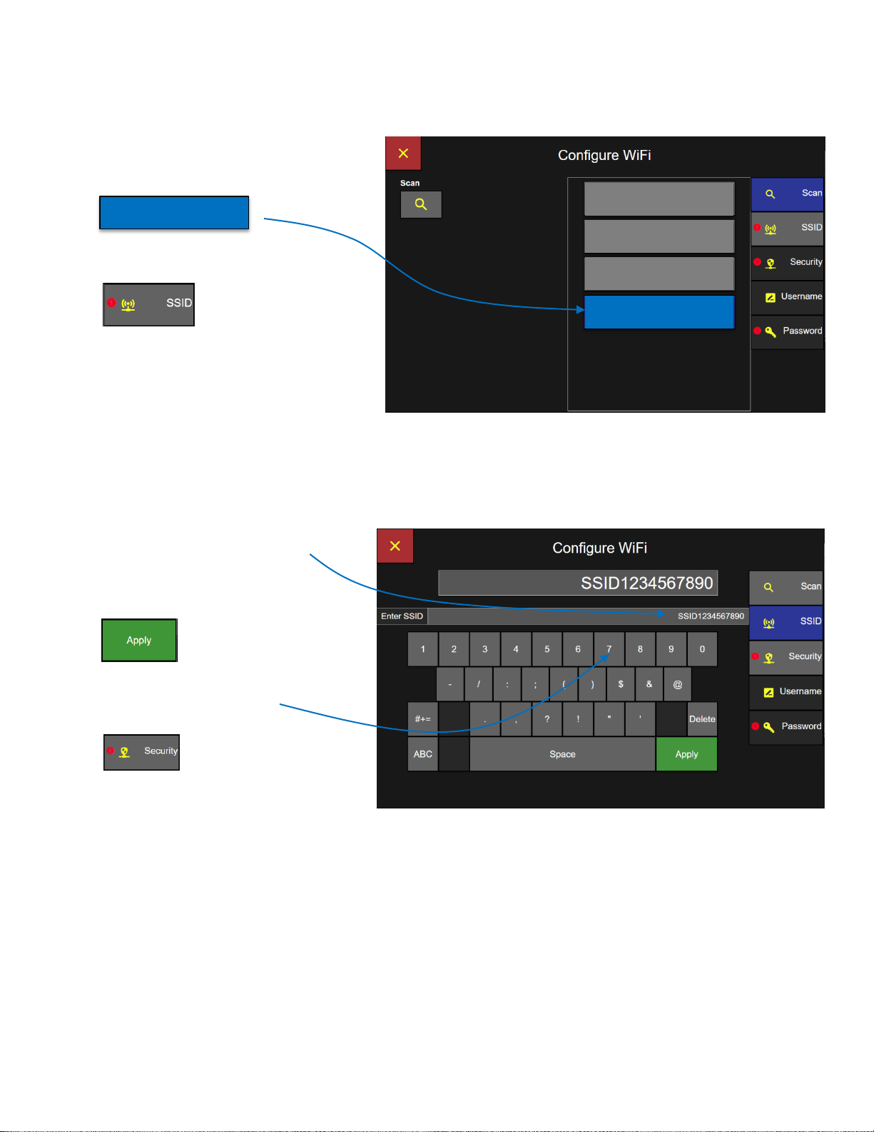
Lighthouse Worldwide Solutions ApexZ Operators Manual
WIFI 1
Enterprise Wi-Fi
Wi-Fi – No Security
Manual
Manual
Connectivity: Wi-Fi Scan Screen
Connectivity: Wi-Fi SSID
Manual Wi-Fi Configuration
Select Wi-Fi
Select Manual Wi-Fi Configuration
Press the SSID button.
.
Enter the SSID with the keypad
Press Apply
Press the Security button.
248083466-1 R6 84
Page 93

Lighthouse Worldwide Solutions ApexZ Operators Manual
Enterprise Wi-Fi configurations:
Security will be preset to WPA-EAP.
Username input is required.
Password input is required.
Connectivity: Wi-Fi Security
Select Wi-Fi Security
Select Security Type.
Security will be selectable only for
Manual Wi-Fi configurations.
Security will be preselected
according to the Wi-Fi type
detected.
WPA-PSK
Wi-Fi Protected Access – Pre-Shared Key
Password required only.
WPA-EAP
Wi-Fi Protected Access – Enterprise
Certificate accepted, not required.
Username required.
Password required.
248083466-1 R6 85
Page 94

Lighthouse Worldwide Solutions ApexZ Operators Manual
Connectivity: Wi-Fi Username
Connectivity: Wi-Fi Password
Enter Username
Enter Username with the key pad.
Then press Apply.
Press the Password Button.
Enter Password
Enter password on the keyboard screen and
press Apply.
Press the Save button to save settings and
connect to Wi-Fi selected.
When the ApexZ successfully connects to the Wi-Fi network, a “Connection Successful” message will appear.
248083466-1 R6 86
Page 95

Lighthouse Worldwide Solutions ApexZ Operators Manual
Note: Active Directory URL and Domain
must be set up and a Test Login performed
before logging in with AD user accounts.
Active Directory AD/LDAP
Contact your IT department
Contact your IT department to obtain the URL and Domain for your Active Directory.
AD URL
Press the URL button and use the keypad
to enter the Active Directory URL.
Then press the green Apply button.
AD Domain
Press the Domain button and use the
keypad to enter the Domain name.
Then press the green Apply button.
Press the Test button to test login to the Active Directory.
248083466-1 R6 87
Page 96

Lighthouse Worldwide Solutions ApexZ Operators Manual
CIFS (Common Internet File System)
The CIFS “ Common Internet File System” is used to connect and export data to shared network drives.
Contact your IT Department for the URL, Path and Folder settings for your CIFS.
CIFS URL
Press the URL button and enter the IP address
using the keypad.
Then press the green apply button.
Path
Press the Path button and enter the CIFS Path using the keypad.
Then press the green apply button.
248083466-1 R6 88
Page 97

Lighthouse Worldwide Solutions ApexZ Operators Manual
Folders 1-2-3
Folder 1, Folder 2, and Folder 3 are designed
to allow the user to organize data into subfolders according to the instruments they
were downloaded from.
Press each Folder button and select the
desired sub folder name from the pop up list:
Serial #
Date
Model
None
Auto Authenticate
Press the enable Auto Authenticate button and ApexZ will use the current logged in user’s credentials to
authenticate with the network drive when exporting data. Disable Auto Authenticate will require every user to
enter their username and password prior to exporting data to the network drive.
Enabled Disabled
Test Authentication
Press the Test button to test Authentication.
248083466-1 R6 89
Page 98

Lighthouse Worldwide Solutions ApexZ Operators Manual
Blank Page
248083466-1 R6 90
Page 99

Lighthouse Worldwide Solutions ApexZ Operators Manual
Home Screen
Configuration: Locations and Groups Screen
Locations and Groups
The ApexZ instrument has the capacity to store up to 2500 location names. The first 250 location names have
been named as “Location 0001”, “Location 0002” and up to “Location 0250”. Additional Location names can be
added and the location name will default to the next sequential location # for example “Location 0251”.
Location names can be easily edited/renamed or deleted.
Groups may also be created and locations may be assigned to Group names. Up to 250 Groups can be created
and locations can be assigned to these groups.
View Locations
From the Home Screen press the Settings
button to display the Settings screen.
From the Settings screen press the Location
button and it will highlight blue and display
the Locations and Groups Screen
Scroll to view all Locations.
ApexZ is shipped with 250 named locations
“Location 0001, Location 0002, …”. These
location names can be renamed or deleted
and additional locations can be created up to
2500 total location names.
248083466-1 R6 91
Page 100

Lighthouse Worldwide Solutions ApexZ Operators Manual
Configuration: Locations and Groups Screen
Add Locations Screen
Create New Locations
Press the + button to Create a New Location.
After pressing the + button the next location
number will be created and named
“Location 0251”.
Add additional locations before saving
Press the + button to add one more location to the list of new locations.
Each new location will be named sequentially “Location 0251, Location
0252, Location 0253… etc.
Press the - Delete button to delete a highlighted location from the list.
Press the Edit button to change the name of the location.
Press the green Save button to add the list of new locations
to the ApexZ database.
248083466-1 R6 92
 Loading...