


ApexPortable
PARTICLE COUNTER
OPERATING MANUAL
ApexP3, ApexP5

00

Lighthouse Worldwide Solutions
ApexPortable Airborne Particle Counter
Operating Manual

Copyright © 2015-2019 by Lighthouse Worldwide Solutions. All rights reserved. No part of this
document may be reproduced by any means except as permitted in writing by Lighthouse
Worldwide Solutions.
The information contained herein constitutes valuable trade secrets of Lighthouse Worldwide
Solutions. You are not permitted to disclose or allow to be disclosed such information except as
permitted in writing by Lighthouse Worldwide Solutions.
The information contained herein is subject to change without notice. Lighthouse Worldwide
Solutions is not responsible for any damages arising out of your use of the LMS program.
LMS™, LMS Express™ and
ApexPortable™ are trademarks of Lighthouse Worldwide
Solutions.
Microsoft
®
, Microsoft Windows™, and Excel™ are trademarks of Microsoft Corporation.
Manufactured by:
Lighthouse Worldwide Solutions
1221 Disk Drive
Medford, Oregon 97501
LWS Part Number 248083440-1 Rev 5

EU DECLARATION OF CONFORMITY
Manufacturer’s Name: Lighthouse Worldwide Solutions, Inc.
Manufacturer’s Address: Lighthouse Worldwide Solutions, Inc.
1221 Disk Drive
Medford, OR 97501
Declares that the product:
Product Name: ApexP Airborne Particle Counters
Model Number(s): ApexP3/ApexP5
Conforms to the following Product Specifications:
SAFETY EN61010-1:2010 Safety Requirements for Electrical Equipment for
Measurement, Control, and Laboratory Use Part
I: General Requirements IEC 61010-1:2010
EMC EN61326-1:2013 Electrical Equipment for Measurement, Control
and Laboratory Use EN 61326-1:2013
Supplementary information
The product herewith complies with the requirements of the Low Voltage Directive 2014/35/EU and the EMC
Directive 2014/30/EC and carries the CE marking accordingly
_________________________________________
Fremont, CA, March 13, 2019 Jerry Szpak – VP Engineering
________
____
__
__
_____
J
y
S
zp
g
err
ak – VP Engineerin


00
Table of Contents
About this Manual
Text Conventions ................................................................................................................ i
Additional Help ................................................................................................................... i
Chapter 1 General Safety
Safety Considerations .................................................................................................... 1-1
LASER Safety Information ........................................................................................... 1-1
Sampling Safety ............................................................................................................. 1-2
Operating Safety ............................................................................................................ 1-2
Electrostatic Safety Information .................................................................................... 1-3
Chapter 2 Introduction
Overview ........................................................................................................................ 2-1
Description ..................................................................................................................... 2-1
Accessories .................................................................................................................... 2-2
ApexP3 Specifications ................................................................................................... 2-3
ApexP5 Specifications ................................................................................................... 2-4
Chapter 3 Get Started
Unpack and Initial Inspection ........................................................................................ 3-1
Configuration Kit ........................................................................................................... 3-1
Interchangeable Terms ....................................................................................... 3-1
Set Channels, Thresholds and Alarms ........................................................................... 3-2
Chapter 4 Communications
General ........................................................................................................................... 4-1
RS485 Communications .................................................................................... 4-2
Remote Run via LMS Software ..................................................................................... 4-3
Chapter 5 Operate the ApexPortable
Using the Instrument for the First Time ........................................................................ 5-1
Touch Screen Overview ................................................................................................. 5-2
248083440-1 Rev 5 t-i

Lighthouse ApexPortable Operating Manual
Menu Map .......................................................................................................... 5-2
MAIN Screen ................................................................................................................. 5-3
Select Location .................................................................................................. 5-6
Locations in AUTO Mode ..................................................................... 5-7
Zoomed Data View ............................................................................................ 5-7
Viewing Two Columns of Data ............................................................. 5-8
CONFIG (Configuration) Screen ................................................................................. 5-10
DATA SETUP ............................................................................................................. 5-11
PARTICLE ...................................................................................................... 5-11
SAMPLE .......................................................................................................... 5-12
SETTING ......................................................................................................... 5-14
Count MODEs ..................................................................................... 5-14
FORMAT ............................................................................................. 5-15
ALARM ........................................................................................................... 5-16
Alarm Threshold .................................................................................. 5-16
CLEAR ............................................................................................................ 5-17
DEVICE SETUP .......................................................................................................... 5-18
CLOCK ............................................................................................................ 5-18
OPTIONS ......................................................................................................... 5-19
Contrast Adjust .................................................................................... 5-20
Audible Beep Adjust ............................................................................ 5-20
ALIGN Touch Screen .......................................................................... 5-20
Autostart Mode .................................................................................... 5-22
Diff+Cuml Zoom ................................................................................. 5-22
One Channel ........................................................................................ 5-23
One Second Realtime Modbus Output ................................................ 5-23
Language .............................................................................................. 5-23
COMM ............................................................................................................. 5-24
COMM Serial Settings ......................................................................... 5-24
Set ETHERNET Settings ..................................................................... 5-25
OUTPUT .......................................................................................................... 5-27
Printer Output ...................................................................................... 5-27
USB Output ........................................................................................ 5-28
Security ........................................................................................................... 5-29
Service ............................................................................................................. 5-30
STATUS ...................................................................................................................... 5-30
RECIPE ........................................................................................................................ 5-31
LOCATION ................................................................................................................. 5-34
Remote Operation ........................................................................................................ 5-36
Data View Buffer Screen ............................................................................................. 5-36
Output Data .................................................................................................................. 5-39
Output Data to USB Printer ............................................................................. 5-39
Output a Range of Records to USB Flash Drive ........................................... 5-39
Report Requirements ....................................................................................... 5-42
Fed Std ft3 ............................................................................................ 5-42
ISO 14644-1 ......................................................................................... 5-42
t-ii 248083440-1 Rev 5

EU GMP 2009 ..................................................................................... 5-42
REPORT FEATURE ....................................................................................... 5-42
Set Up Report Room Parameters ..................................................................... 5-44
Set Up Counter to Run Reports ....................................................................... 5-49
Save Report ...................................................................................................... 5-51
Generate a Report From Data .......................................................................... 5-52
Printing a Previously Printed Report ............................................................... 5-54
Web Reports Interface ......................................................................... 5-55
Web Page Reports ................................................................................ 5-56
Sample Printouts of Standard Reports ................................................. 5-58
Power Shutdown Levels .............................................................................................. 5-61
Chapter 6 Maintenance Procedures
Introduction .................................................................................................................... 6-1
Safety ............................................................................................................................. 6-1
Maintenance ................................................................................................................... 6-1
Calibration ......................................................................................................... 6-1
Zero Count Test ............................................................................................................. 6-1
Fault Isolation ................................................................................................................ 6-2
Table of Contents
Chapter 7 Program with the MODBUS Protocol
General Info ................................................................................................................... 7-1
Protocol Settings ............................................................................................................ 7-1
Power On/Auto Start ...................................................................................................... 7-1
Running the Instrument Using MODBUS ..................................................................... 7-1
AUTOMATIC Counting Mode ......................................................................... 7-2
Configuring with the MODBUS Protocol ..................................................................... 7-3
Setting the Real Time Clock .............................................................................. 7-3
Changing the Default Instrument Parameters .................................................... 7-4
Using Sensor Setting Registers .............................................................. 7-4
Location (Register 40026) ..................................................................... 7-5
Hold Time (Registers 40031, 40032) .................................................... 7-5
Sample Time (Registers 40033, 40034) ................................................ 7-5
Alarm Enable Registers ..................................................................................... 7-6
Enable Alarming for a Channel ............................................................. 7-7
Threshold Setup Registers ................................................................................. 7-7
Setting the Alarm Threshold Value ....................................................... 7-8
Appendix A ApexPortable MODBUS Register Map v1.50
COMM Settings ............................................................................................................ A-1
Supported MODBUS Commands ................................................................................. A-1
Sensor Settings Registers .................................................................................. A-2
248083440-1 Rev 5 t-iii

Lighthouse ApexPortable Operating Manual
Device Status ........................................................................................ A-5
Alarm Enable Registers .................................................................................... A-8
Enable Alarming for a Channel ............................................................ A-9
Threshold Setup Registers .............................................................................. A-10
Setting the Alarm Threshold Value .................................................... A-10
Data Registers ............................................................................................................. A-11
Device Status Word ........................................................................................ A-14
Data Enable Registers ..................................................................................... A-15
Data Type Registers ........................................................................................ A-15
Data Units Registers ....................................................................................... A-17
Appendix B Limited Warranty
Limitation Of Warranties: .............................................................................................. B-1
Warranty Of Repairs After Initial Two (2) Year Warranty: .......................................... B-1
Index
t-iv 248083440-1 Rev 5

00
About this Manual
This manual describes the detailed operation and use of the Lighthouse
ApexPortable (ApexP3 and ApexP5) portable airborne particle
counters.
Text
Conventions
Note:
A note appears in
the sidebar to give extra
information regarding a
feature or suggestion.
WARNING:
appears in a paragraph
like this and indicates a
condition, which if not
met, could cause serious
personal injury or death,
and damage to the
instrument.
A warning
Additional
Help
The following typefaces have the following meanings:
italics Represents information not to be typed
or interpreted literally. For example, file
represents a file name. Manual titles are
also displayed in italics.
boldface Introduces or emphasizes a term.
Courier font Indicates command syntax or text
displayed by the diagnostic terminal.
Bold Courier Indicates commands and information that
the user types.
Helvetica Italics Indicates a comment on a command or
text output.
For more information about Lighthouse ApexPortable Airborne Particle
Counters, contact Lighthouse Worldwide Solutions.
Service and Support
Tel: 1-800-945-5905 (Toll Free USA)
Tel: 1-541-770-5905 (Outside of USA)
techsupport@golighthouse.com
248083440-1 Rev 5 i

Lighthouse ApexPortable Operating Manual
ii 248083440-1 Rev 5

00
1 General Safety
Safety
Considerations
WARNING:
no user-serviceable
components inside the
particle counter.
There are
LASER Safety
Information
Warnings and cautions are used throughout this manual and the reader
should become familiar with the meaning of a warning before
operating the particle counter. Most warnings will appear in the left
margin of the page next to the subject or step to which it applies. Take
care when performing any procedures preceded by or containing a
warning. The classifications of warnings are defined as follows:
• LASER - pertaining to exposure to visible or invisible LASER
radiation
• Electrostatic - pertaining to electrostatic discharge
• Network Connect - pertaining to communication ports and
instrument damage
This product is considered to be a Class 1 LASER product (as defined
by FDA 21 CFR, §1040.10 and IEC 60825-1:2014) when used under
normal operation and maintenance. Performing service on the internal
sensor can, however, result in exposure to invisible radiation.
WARNING:
of controls, adjustments
or procedures other than
those specified within
this manual may result in
personal injury and/or
damage to this
instrument.
248083440-1 Rev 5 1-1
The use
The particle counter has been evaluated and tested in accordance with
EN 61010-1:2012, “Safety Requirements For Electrical Equipment for
Measurement, Control and Laboratory Use” and IEC 60825-1:2014,
“Safety of LASER Products”.
For further technical assistance, contact our Technical Support Team at
1-800-945-5905 (USA Toll Free), 1-541-770-5905 (Outside of USA).

Lighthouse ApexPortable Operating Manual
Sampling
Safety
Operating
Safety
WARNING: While the flow path components will not be
adversely affected, sampling reactive gasses such as
hydrogen and oxygen can be dangerous. Appropriate
precautions should be taken.
Sampling of any pressurized gasses without the use of a
properly designed diffuser can cause damage to the
instrument and void the warranty.
Do NOT allow water, solvents, or other liquids to enter the
instrument as they can damage the instrument and void the
warranty.
WARNING: The use of controls, adjustments or procedures
other than those specified within this manual may result in
personal injury and/or damage to this instrument. Attempts
by untrained personnel to disassemble, alter, modify or
adjust the electronics or optics may result in personal injury
and damage to the instrument and will void its warranty.
There are no user-serviceable components inside the
particle counter. Only factory authorized service personnel
should repair or service this instrument and its optical
system.
If replacement of the power supply or its AC power cord is
required, replace it only with a power supply or cord having
as good as or better ratings than specifications provided by
Lighthouse Worldwide Solutions. Attempting to use an
under-rated power supply or cord can expose the
instrument, adjacent equipment or the user to dangerous
shock and fire hazards. Failure to meet this requirement will
void the CE certification, void the instrument warranty and
can result in serious personal injury.
1-2 248083440-1 Rev 5

General Safety
WARNING: The
ApexPortable uses a
5 Amp 24V DC power
supply. It connects to
the round connector
shown in Figure 1-1.
Remove AC power from
power supply, connect
DC cord to Apex then
connect power supply to
AC.
Electrostatic
Safety
Information
24VDC
Input
Connector
Figure 1-1 ApexPortable Power Input Connector
Electrostatic discharge (ESD) can damage or destroy electronic
components. Therefore, any service or maintenance work should be
done at a static-free work station. A static-free work station requires an
ESD consultant to evaluate the work environment and propose the
equipment and apparel needed for a work station to be successful.
248083440-1 Rev 5 1-3

Lighthouse ApexPortable Operating Manual
1-4 248083440-1 Rev 5

00
2 Introduction
Overview This operating manual introduces the Lighthouse ApexPortable
family of portable Airborne Particle Counters and includes instructions
for inspecting, installing, using and maintaining the instrument.
Description The ApexPortable instrument comes standard with four particle-size
channels of 0.3, 0.5, 1.0 and 5.0 microns (
and 10.0 microns (
the standard configuration. Figure 2-1 lists features and specifics about
the
ApexP3 and Table 2-2 lists the ApexP5.
ApexP5) with a flow of 1.0 CFM. Figure 2-1 shows
ApexP3) and 0.5, 1.0, 5.0
Figure 2-1 ApexPortable Airborne Particle Counter
The instrument uses a LASER diode light source and LASER beam
shaping optics to illuminate a cross section of the air flow path. As
particles move along this path, they cross the LASER beam and scatter
light. The light scattered is collected by an optical imaging system onto
a photodiode. The photodiode converts the image into a current which
is converted to a voltage and amplified by an electronic circuit.
The result is the electronic circuit outputs a voltage pulse each time a
particle crosses the LASER beam. The amplitude of the voltage pulse
is proportional to the light scattered which in turn is proportional to the
size of the particle.
248083440-1 Rev 5 2-1

Lighthouse ApexPortable Operating Manual
The voltage pulses created by the particles are then processed by
additional electronics that analyze the height of each pulse, therefore,
the size of each corresponding particle. The result is that the number of
particles of various sizes is determined.
The processed signals are sorted into bins, or channels, and displayed
on the screen as counts. The terms Particle Size and Particle Channel
are used synonymously to refer to the displayed information.
This instrument is effective in both ultra-clean areas (such as ISO Class
1 or Grade A) and in more traditional cleanzones rated as ISO Class 3
or higher. Refer to Specifications in this manual for additional
instrument information.
The
ApexPortable integrates seamlessly with large facility monitoring
and management systems and transfers particle count data using RS485
(using MODBUS RTU or ASCII protocols) or Ethernet via MODBUS
TCP.
Accessories Several items are shipped with each instrument but some optional
accessories can be ordered to tailor the instrument to specific needs.
Standard and optional accessories are listed below.
• Standard Accessories:
• 24VDC 5A Power Supply
• Operating Manual on included flash drive
• LMS Express Download Instructions
• Read Me First
•Parts List
• USB to RS-232 Serial cable
• 1.0 CFM Isokinetic Sampling Probe with Tubing
• 1.0 CFM Purge Filter Assembly with Tubing
• Optional Accessories:
• USB Thermal Printer and Operating Manual on CD
• Cable, per foot
• Sample Tubing, per foot
• ISO Probe Monopod
2-2 248083440-1 Rev 5

ApexP3
Specifications
Introduction
Size Range 0.3 - 5.0 μm
Channel Thresholds Standard 2-channel: 0.3, 0.5μm; 4-channel:
0.3, 0.5, 1.0, 5.0μm
Flow Rate 1.0 CFM (28.3 LPM)
Counting Efficiency Meets ISO 21501-4
Data Storage Rotating Buffer, 3000 records
Light Source LASER diode
External Connections RS485 RJ45 (RS485 and RS232 data); DIN
(factory); Ethernet RJ45 (Ethernet data);
calibration port
Zero Count Level <1 count/5 minutes (per ISO 21501-4)
Max ISO Probe tubing Maximum tubing length to ISO = 16 feet
Calibration NIST Traceable
Communication Modes MODBUS ASCII; MODBUS RTU;
Supporting Software LMS Pharma/Pro v7.3.1 or higher, LMS
Operating Altitude Sea Level to 2000 meters (6561.66 feet)
Power Input
Requirements
Power Supply
Specifications
Enclosure Stainless Steel, VHP compatible
Dimensions
Weight
Operating Temp/RH 50° F to 104° F (10° C to 40° C) / 20% to 95%
Storage Temp/RH 14° F to 122° F (-10° C to 50° C) / Up to 98%
Table 2-1 ApexP3 Specifications
MODBUS TCP
Express 7.5 or higher
24VDC ±5% @ 5.0A, 120W
100-240VAC, 47-63Hz 1.4A input, 24VDC
5.0A 120W max output
9.00” (w) x 8.46” (h) x 6.21” (d) [22.86 x 21.49 x
15.77 cm]
10.0 lbs (4.54 kg)
non-condensing at maximum 2000M altitude
non-condensing
248083440-1 Rev 5 2-3

Lighthouse ApexPortable Operating Manual
ApexP5
Specifications
Size Range 0.5 - 10.0 μm
Channel Thresholds Standard 2-channel: 0.5μm, 5.0μm; 4-channel
Flow Rate 1.0 CFM (28.3 LPM)
Counting Efficiency Meets ISO 21501-4
Data Storage Rotating Buffer, 3000 records
Light Source LASER diode
External Connections RS485 RJ45 (RS485 and RS232 data); DIN
Zero Count Level <1 count/5 minutes (per ISO 21501-4)
Max ISO Probe tubing Maximum tubing length to ISO = 16 feet
Calibration NIST Traceable
0.5, 1.0μm, 5.0μm, 10.0μm
(factory); Ethernet RJ45 (Ethernet data);
calibration port
Communication Modes MODBUS ASCII; MODBUS RTU;
MODBUS TCP
Supporting Software LMS Pharma/Pro v7.3.1 or higher, LMS
Express 7.5 or higher
Operating Altitude Sea Level to 2000 meters (6561.66 feet)
Power Input
24VDC ±5% @ 5.0A, 120W
Requirements
Power Supply
Specifications
100-240VAC, 47-63Hz 1.4A input, 24VDC
5.0A 120W max output
Enclosure Stainless Steel, VHP compatible
Dimensions
Weight
9.00” (w) x 8.46” (h) x 6.21” (d) [22.86 x 21.49 x
15.77 cm]
10.0 lbs (4.54 kg)
Operating Temp/RH 50° F to 104° F (10° C to 40° C) / 20% to 95%
non-condensing at maximum 2000M altitude
Storage Temp/RH 14° F to 122° F (-10° C to 50° C) / Up to 98%
non-condensing
Table 2-2 ApexP5 Specifications
The manufacturer recommends that the Lighthouse instrument be
calibrated annually by a Lighthouse Certified Service Provider in order
to ensure the unit continues to perform within specifications and to
protect its warranty. For information about returning instruments for
calibration or service, visit our website www.golighthouse.com/RMA.
2-4 248083440-1 Rev 5

3 Get Started
Get Started
Unpack and
Initial
Inspection
Configuration
Kit
The instrument is thoroughly inspected and tested at the factory and is
ready for use upon receipt.
When the instrument is received, inspect the shipping carton for
damage. If any is noted, ensure that the carrier is notified and the carton
is saved for carrier inspection. Remove the instrument and other
components from the packing materials and inspect them for broken
parts, scratches, dents, and other damage. Compare the contents with
the pack slip / invoice / parts list. Immediately report any damaged or
missing parts to Lighthouse.
Damaged cartons may be replaced by calling Lighthouse Sales. Keep
an undamaged carton for reshipment of the instrument for its annual
factory calibration.
Report all issues to Lighthouse Support at 1-800-945-5905 in the USA
or 1-541-770-5905 outside of USA.
Each order is shipped with a Ship Kit, which includes a 24VDC Power
Supply and a flash drive containing the Operating Manual.
Interchangeable Terms
The terms ApexPortable, instrument, counter and unit may be used
throughout this manual interchangeably; they mean the same thing
unless specified otherwise.
248083440-1 Rev 5 3-1

Lighthouse ApexPortable Operating Manual
Figure 3-1 ApexPortable Connectors
WARNING: Remove
AC power from Power
Supply, connect DC
cable then connect to
AC.
Set Channels,
Thresholds,
and Alarms
Always have the AC disconnected from the power supply before
attempting to connect the DC Output Connector to the ApexPortable.
This will prevent damaging the Power Input Connector.
It is suggested that the
ApexPortable be placed in the environment
where it will be used and attached to its power supply for several hours
to ensure its battery is fully charged before putting the instrument into
service.
Push the rear power button (see the image above) in to turn the
instument on - it should latch in the ON state. After about 5 seconds,
the unit will display its boot screen then display the Main Screen. The
following screens will display how to enable channels, set alarm levels
and enable the alarms. They are provided as examples and may vary on
individual instruments.
3-2 248083440-1 Rev 5

Quick Setup Guide:
Tou c h th e
CONFIG
button
Then
PARTICLE
Figure 3-2 MAIN Screen
Get Started
Figure 3-3 Config Screen Choose Particle
Enabled
Enable
Desired
Channels
Press the button
to
toggle state
Disabled
then press BACK
Figure 3-4 Particle Channel ON/OFF Setting
Press a to change its state to a to enable the channel.
Press a to change its state to a to disable the channel.
248083440-1 Rev 5 3-3

Lighthouse ApexPortable Operating Manual
When CONFIG
screen returns,
press ALARM
to enter the
Particle Alarm
screen
Figure 3-5 Config Screen - Choose Alarm
press a
button to
change
the alarm
threshold
Figure 3-6 Particle Alarm Enable/Disable
Use the
Numeric
Keypad
to enter
desired
values
followed by the ENTER
button
Disabled
Enabled
Press the button
to
toggle state
Acts
as a
backspace
Figure 3-7 Alarm Threshold Change Screen
3-4 248083440-1 Rev 5

Get Started
Return to
MAIN
screen
and note
that only
enabled
channels
are
displayed
Figure 3-8 Enabled Channels Displayed
Figure 3-8 shows enabled channels and the ’>’ indicates channels that
have alarms enabled, in this case both channels.
At this point, pressing the START button will start the
ApexPortable
counting cycle on the enabled channels. Please refer to Chapter 5,
Operating Counter, for detailed operating instructions for the
instrument.
248083440-1 Rev 5 3-5

Lighthouse ApexPortable Operating Manual
3-6 248083440-1 Rev 5

00
4 Communications
This chapter contains information regarding how to set up
communications to program and communicate with the
instrument.
General Table 4-1 lists the Communication Port (COMM Port) RJ45 pinouts.
Prevent accidental damage to Ethernet hardware: do NOT connect the
COMM port to Ethernet equipment, such as network switches, hubs
and the like.
Table 4-1 COMM Port RJ45 Pinouts
ApexPortable
RJ45 Pin Signal Name
1 RS232-TX (Output)
2 RS232 RX (Input)
3 RESERVED for future use
4 RS485B
5 RS485A
6 RESERVED for future use
7 RESERVED for future use
8 Ground
To connect the instrument to a computer using USB-to-RS232 cable:
1. Remove power from the instrument.
2. Connect the RJ45 end of a USB-to-RS232 or RS485 cable to the
RS485 RJ45 connect port on the instrument.
3. Connect the USB end of the cable to any computer USB Port.
248083440-1 Rev 5 4-1

Lighthouse ApexPortable Operating Manual
RS485 Communications
RS485 should be used if the instrument is more than 50 feet from the
computer or is installed in an industrial network. To do so, an optional
RS485 cable must be used. Refer to Table 4-2 for specifics about the
RS485 standard.
Table 4-2 shows the Electronics Industry Association (EIA) industry
standards specifications.
Table 4-2 EIA Industry Standards for RS485 Communications
SPECIFICATIONS RS485
Mode of Operation Differential
Total Number of Drivers and Receivers on
One Line (One driver active at a time for
32 Drivers
32 Receivers
RS485 networks)
Maximum Cable Length 4000 ft (1,219.2 m)
Maximum Data Rate (40 ft - 4000 ft for
100Kbs - 10Mbs
RS422/RS485)
Maximum Driver Output Voltage -7V to +12V
Driver Output Signal Level (Loaded
+/-1.5V
Min.): LOADED
Driver Output Signal Level (Loaded
+/-6V
Max.): UNLOADED
Driver Load Impedance (Ohms) 54
Max Driver Current in High Z State
+/-100μA
(POWER ON)
Max Driver Current in High Z State
+/-100μA
(POWER OFF)
Receiver Input Voltage Range -7V to +12V
Receiver Input Sensitivity +/-200mV
Receiver Input Resistance (Ohms), (1
>
12k
Standard Load for RS485)
4-2 248083440-1 Rev 5

Communications
Ethernet Port
SmartPort
COMM Port
Power Input
Connector
WARNING: The
ApexPortable uses a 5
Amp 24V DC power
supply. It connects to the
round connector shown
on the left in Figure 4-1.
The symbol shows the
voltage and polarity of
supplied power.
Figure 4-1 ApexPortable Rear Connectors
The ApexPortable uses Ethernet for large scale communication,
RS485 for industrial networks and RS232 for direct connection to
monitoring computers.
Remote Run
via LMS
Software
WARNING: Always have the AC disconnected from the power
supply before attempting to connect the DC Output Connector to
ApexPortable. This will prevent damage to the Power Input
Connector.
Only use the power cord provided with the instrument. If it
becomes necessary to replace the power cord or the power
supply, contact Lighthouse Service. Failure to heed this warning
may subject the user and equipment to a shock or fire hazard,
which may result in serious bodily injury and property damage.
The ApexPortable can be remotely accessed, started, stopped and run
by LMS Express Standard, LMS Express RT, LMS Net, Professional
and Pharma software products. The LMS software can retrieve the data
and present it in several user-set reports and report formats.
Facility monitoring products, such as the LMS Net, LMS Professional
or LMS Pharma, provide facility-wide and enterprise-wide monitoring,
alerting and reporting features that use the
ApexPortable environment
monitoring functions.
248083440-1 Rev 5 4-3

Lighthouse ApexPortable Operating Manual
4-4 248083440-1 Rev 5

00
5 Operate the
ApexPortable
Using the
Instrument for
the First Time
WARNING:
flow path componenets
will not be adversely
affected, sampling
reactive gases such as
hydrogen and oxygen
can be dangerous.
Appropriate precautions
should be taken.
Sampling of any
pressurized gasses
without the use of a
properly designed
diffuser can damage the
instrument and void its
warranty.
Please contact
Lighthouse at 1-800-9455905 (USA Toll Free) or 1541-770-5905 (Outside of
USA) for more
information.
While the
This chapter describes how to use the ApexPortable 1.0 CFM
Airborne Particle Counter. The ApexPortable battery is fulled charged
when it leaves the factory, but should be connected to external power
before initial power up.To start using the instrument, proceed as
follows:
WARNING: To prevent damage to the instrument, water, solvents or
other liquids of any kind must never be allowed to enter the
ApexPortable via the inlet tube. Failure to heed this warning can void
the warranty. Never operate the instrument with the inlet tube capped or
plugged. Failure to heed this warning may damage the internal pump
and void the
ApexPortable warranty.
1. Position the instrument in the environment to be measured.
2. Attach the external Power Supply and connect AC cord to AC.
3. Remove the protective cap from the inlet barb located on the top
of the unit. To use the isokinetic probe, attach the probe to the
instrument’s inlet barb using the tubing on the probe.
4. Press in on the rear power switch.
5. While booting, the unit displays a startup "splash" screen.
6. The MAIN screen displays.
7. On the touch screen, press the “START” button to start the
instrument.
8. "STARTING" will display when the pump starts running.
9. When the
ApexPortable starts counting, "COUNTING" appears
on the display. Particle counts are displayed according to which
size channel detected each particle.
248083440-1 Rev 5 5-1

Lighthouse ApexPortable Operating Manual
10. If the instrument has been programmed with a delay before
starting the pump, it displays, “DELAY”.
11. If the instrument is in AUTO mode with cycles and a hold time,
“HOLDING” will display after each cycle and “FINISHED” will
display when all the cycles are complete.
12. Press the "STOP" button to stop the instrument before the cycles
are complete. "STOPPED" will display on the screen.
Touch Screen
Overview
The ApexPortable incorporates a unique touch screen interface, which
allows the user to easily view and configure the instrument to specific
needs and applications. Figure 5-1 shows the menu tree.
Menu Map
Figure 5-1 Menu Map
5-2 248083440-1 Rev 5

Operate the ApexPortable
MAIN Screen The MAIN screen provides a snapshot view of the status of the
instrument. The instrument can be powered by AC power or the
internal battery. When the instrument is using battery power, the
battery indicator will show the approximate level and percentage of the
battery charge remaining as shown in Figure 5-2.
Note:
examples in this chapter
are for reference, only. The
values displayed may not
be indicative of actual
values.
The screen
Figure 5-2 MAIN Screen - Battery Operation
Figure 5-3 MAIN Screen - AC Operation
When an AC-powered power supply is attached, the battery changes to
one with a lightening bolt. Its approximate capacity is displayed as a
percentage above the icon. See Figure 5-3.
The MAIN screen displays the following options and information:
• LOC: Displays the location that is currently being measured. Up to
200 alphanumeric locations can be configured.
• Location Select button: At the MAIN screen, displays an
Abbreviated Location Screen that allows a user to change location
before sampling without requiring use of the CONFIG screen and
any associated password.
248083440-1 Rev 5 5-3

Lighthouse ApexPortable Operating Manual
Depleted Battery
Warning ICON
Full and
Depleted and
Charging
Charging
InsufficientSufficient
• RECIPE button: Allows the user to view, load and unload recipes
that have been configured and saved in the recipe data base via an
Abbreviated Receipe Screen. To edit the recipe or to add or delete
recipes, use CONFIG, which can be password-protected, from the
MAIN screen (see Figure 5-47). The CONFIG password is not
required here.
• Last-Sampled Record Print/USB Save: Indicates attached printer
or flash drive to be used to output the Last-Sampled Record
currently on the screen. Press the Print ICON to send to the
attached printer or USB ICON to send to flash drive. Restart will
clear the screen and nothing will be output.
• Date/Time: Displays the current date and time.
Note:
Users can continue to
run samples and take counts
while the unit is plugged in.
• Battery ICONs: Indicate that the instrument is being powered by
the rechargeable battery or its external power supply. The amount
of battery life left is depicted by the fill inside the battery icon and
the percentage above the icon. When the battery reaches 20%
charge, the ICON will start blinking and display a "BATTERY
LOW!" message. When it reaches 5% and the user tries to run a
sample, the large "Depleted" ICON shown on the left is displayed
and the unit will not run the pump until instrument is attached to the
external DC power supply for recharging.
WARNING:
Flow is insufficient, check
for and remove any
obstructions. If the issue
persists, turn the Apex off
and contact Lighthouse
Worldwide Solutions
technical support at 1945-5905 (USA Toll Free)
or 1-541-770-5905
(Outside of USA)
If the Air
800-
.
• While connected to the power supply, the battery icon changes to
indicate charging. See Figure 5-4.
Depleted Full
Figure 5-4 Battery Levels, On-Battery and Charging
On-Battery
Charging
• Flow Status: When the instrument is COUNTING, the Flow ICON
(left of battery) appears and displays sufficient or insufficient flow.
•USB: Indicates that a USB printer or flash drive is attached.
5-4 248083440-1 Rev 5

Operate the ApexPortable
• Service Indicator: Indicates that the instrument may be in need of
service. If wrench displays, please contact a Lighthouse authorized
Service Provider at 1-800-945-5905 (USA Toll Free) or 1-541-7705905 (Outside of USA) for assistance or send an email to
techsupport@golighthouse.com.
•
μ: The mu (m-yoo) symbol indicates the particle sizes, in
micrometers, configured for the instrument. These sizes are preconfigured at the factory. To order an instrument with non-standard
sizes, please contact a Sales at Lighthouse 510-438-0500 (Sales).
• DATA DISPLAY: This indicates whether the counts are being
displayed in Differential (Diff) mode or in Cumulative (Cuml)
mode and, if the counts are normalized to ft
3
or m3.
Differential
Normalized ft
3
Cumulative
Normalized m
3
•MODE: Displays the current mode selected; possible modes are
AUTO, MANUAL, CONC (Concentration) and BEEP. The
exception to this is when a recipe is being run in which case the
MODE area will display number of cycles run versus the total to be
run (x / 6).
•CYCLES: Indicates the number of times the count will be taken at
a given location in Auto mode. "1/ 3" indicates the count is the first
of three samples to be recorded at this location. The maximum
number of cycles is 999. When set to 0, the unit will run in Auto
mode continuously until the STOP button is pressed.
• SAMPLE: The Sample Time (hh:mm:ss) is the duration of one
counting cycle. The Sample Time will count down on the MAIN
screen when the instrument is in AUTO or Manual mode so the user
can see how much time is remaining in the sample period. In
Concentration mode, the Sample Time will count up to 6 seconds
per cycle.
Note:
greater than 1 minute, the
pump will stop during that
time. At the end of the hold
time, the pump will restart.
If Hold time is
•HOLD: Displays the hold time in between cycles. The maximum
hold time is 23 hours, 59 minutes, 59 seconds.
•RECS: This displays the current number of records stored in the
instrument and the total number of records that can be stored. The
data buffer is a circular buffer. The instrument can store up to 3000
records. An asterisk (*) will appear in front of counts when the
buffer wraps.
248083440-1 Rev 5 5-5

Lighthouse ApexPortable Operating Manual
• START/STOP: Press START button on the screen to start
counting. STARTING is displayed on the screen until the pump
and support electronics are stable and the
reliably count particles. COUNTING will display in the lower right
corner of the screen as shown in Figure 5-5 when the
ApexPortable is actually counting. When the STOP button is
pressed to stop counting, the word STOPPED will be displayed.
• The instrument may be stopped during sampling by an errorchecking process for insufficient battery power, pump over-current
or instrument over-temperature. Acknowledge the popup by
pressing the OK button to try to return to normal operation. If the
error condition persists, contact Lighthouse support.
ApexPortable can
Counting State
Figure 5-5 Three Counting States
Select Location
The location for the measured environment can be changed by pressing
the LOCATION button at the top of the MAIN screen. Figure 5-6
displays the abbreviated Select Location screen. To edit, add or delete
locations, the CONFIG button must be used, which can be passwordprotected. The password is not required here.
Figure 5-6 Location Select Screen
5-6 248083440-1 Rev 5

Operate the ApexPortable
Note: Also see Figure 5-
54 for more information on
Locations.
• The blue highlight indicates which location is currently selected.
• Use the UP and DOWN arrows to highlight a location. The arrows
will move pages up and down. Press on the location name desired
to select the location. A location that has been assigned to a recipe
will display an asterisk at the end of its name.
• When a highlighted location uses a specific recipe, it will be
prompted to load when the MAIN button is pressed.
• The AUTO INC button, when active, pauses the
ApexPortable to
allow the user to move the ApexPortable to the next location when
the current cycle is completed. It waits for the user to ackowledge
the change by pressing the Start button to continue counting at the
new location.
• Press the MAIN button to return to the MAIN screen. Whichever
location that was highlighted / selected will be the location
displayed on the MAIN screen.
Locations in AUTO Mode
When the instrument is in Automatic Mode and the START button is
pressed, the instrument will start counting particles automatically based
on the SAMPLE time, HOLD time and number of cycles that are
configured.
Zoomed Data View
There are two different Zoom views. The user can view a single
column of data (differential or cumulative) in a larger font or view both
differential and cumulative data on the same screen in a smaller font.
While the ApexPortable is stopped, tap anywhere in the Particle Data
area to display the Zoomed Data View. See Figure 5-7.
Figure 5-7 Zoomed Data View
248083440-1 Rev 5 5-7

Lighthouse ApexPortable Operating Manual
In the Zoomed Data View, functions can be enabled using the buttons
on the right side bar of Figure 5-7. Figure 5-8 shows examples and
explanations of the buttons.
START or STOP counting
Display Cumulative / Differential data
Display Raw / Normalized particle data
Display ft
3
/ m3 when configured
Figure 5-8 Zoomed Data View Buttons
When the instrument is STOPPED or HOLDING, the user may touch
anywhere in the white data area to return to the MAIN Screen view.
Viewing Two Columns of Data
The
ApexPortable can display both Differential and Cumulative data
at the same time on the Zoomed View screen. Press the CONFIG then
OPTIONS button to display the Options screen (Figure 5-9).
Figure 5-9 CONFIG: Options Screens
5-8 248083440-1 Rev 5

Operate the ApexPortable
START or STOP counting
Display Cumulative / Differential data
Display Raw / Normalized particle data
Display ft
3
/ m3 when configured
Press the “Diff+Cuml Zoom” button as shown in Figure 5-9, right
frame, to enable the feature. This will display both differential and
cumulative data on the Zoomed View screen as shown in Figure 5-10.
DIFF
Data
CUML
Data
Figure 5-10 Differential and Cumulative Data in Zoomed View
The buttons available after selecting Diff+Cuml Zoom are shown in
Figure 5-11. Their functions are the same as on single display screen.
Figure 5-11 Diff+Cuml Zoom Screen Button Actions
To return the instrument to the default single-column zoom view, return
to the MAIN Screen, press CONFIG, Options and deselect the
“Diff+Cuml Zoom” button. See Figure 5-9.
Press the MAIN button to return to the MAIN Screen or press BACK to
return to the previous level where the data type to be displayed on the
one-column Zoomed View screen is chosen.
248083440-1 Rev 5 5-9

Lighthouse ApexPortable Operating Manual
Go to the Settings screen and press Differential or Cumulative for the
data type. See Figure 5-12.
Figure 5-12 Settings Screen
CONFIG
(Configuration)
Screen
Press CONFIG on the MAIN screen to display the Configuration
screen as shown in Figure 5-13. This feature can be passwordprotected.
Figure 5-13 Configuration Screen
DATA SETUP provides buttons to enable/disable particle channels, set
sample record parameters, sample settings, thresholds, enable/disable
alarms and clear the data buffer.
DEVICE SETUP provides buttons to configure the instrument’s date
and time, set the LCD contrast, adjust the instrument’s beep volume,
enable the instrument to AutoStart, set it to display only one channel of
data, enable real-time MODBUS output, set the instrument’s
communication address, enabling output on sample, enable password
restrictions and/or (with proper authorization) adjust service settings.
5-10 248083440-1 Rev 5
Operate the ApexPortable
Disabled
Enabled
Press button to
Change State
then
Enable the
particle
sizes to
be measured
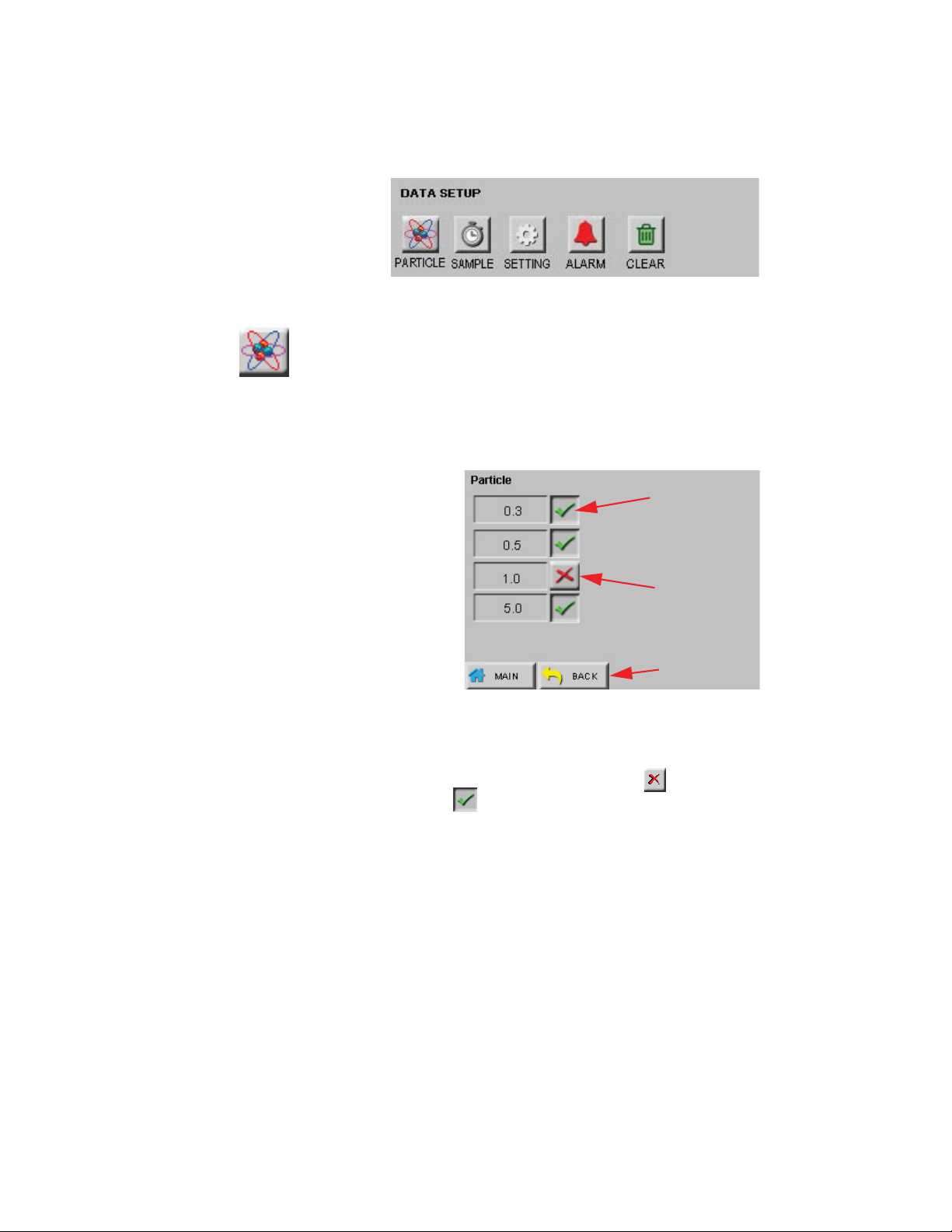
DATA SETUP Figure 5-14 shows the Data Setup option buttons. These options allow
the user to configure the parameters for data collection.
Figure 5-14 Data Setup Options
PARTIC LE
The instrument’s particle channels can be enabled or disabled on the
Particle screen. A checkmark is displayed next to each enabled
channel. See Figure 5-15.
Figure 5-15 Particle Channel Configuration
• The button on the right of each channel size is an ON/OFF toggle.
Press once to toggle a channel between a , disabling the channel
and the default , enabling the channel.
When channels are disabled, they are removed from the MAIN screen
display, from the reports and from the printouts.
248083440-1 Rev 5 5-11
Lighthouse ApexPortable Operating Manual
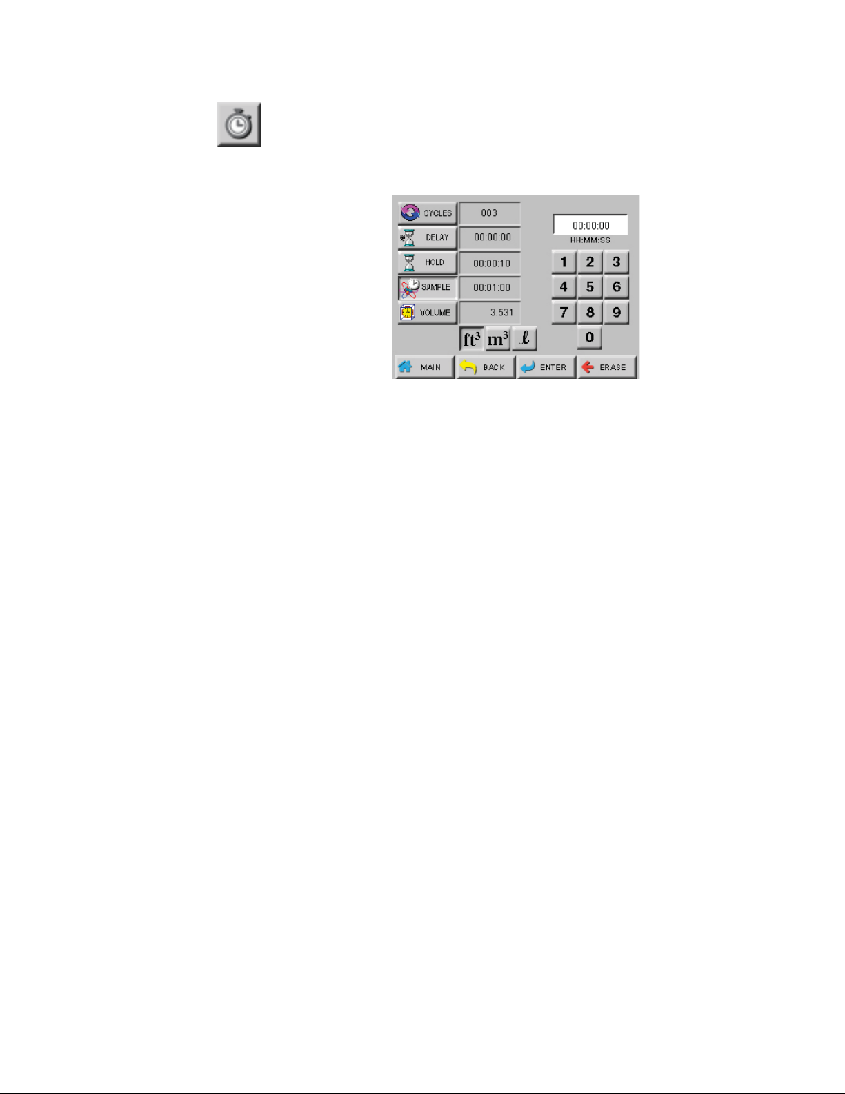
SAMPLE
The SAMPLE screen configures the number of cycles, count times and
volumes during a sample run. See Figure 5-16.
Figure 5-16 Sample Timing Configuration Screen
•CYCLES: The number of cycles is set to determine how many
times the instrument samples the air in a single location. This is
applicable only in AUTO mode. The range is 0 - 999. When
CYCLES is set to 0, the instrument will continue running samples
indefinitely until the STOP button is pressed.
Note:
set to 00:00:00 in Auto
Mode, the instrument will
run the samples according
to the sample time and the
# of cycles, but with no
hold time in between
cycles.
If the Hold time is
Press the CYCLES button; enter the number of desired cycles using
the numeric keypad on the right. Press ERASE to erase a number,
if needed. Press ENTER to set/save the Cycles.
• DELAY: The Initial Start Delay (hh:mm:ss) is the time between
when the START button is pressed and the unit actually starts
counting.
The Initial Start Delay gives the operator time to exit the area under
test so that the measurement is taken under a controlled condition.
The maximum delay time is 23 hours, 59 minutes and 59 seconds.
Press the DELAY button; enter the initial delay time in hours,
minutes and seconds using the numeric keypad. After the value is
entered, press ENTER.
• HOLD: The Hold Time (hh:mm:ss) is the time between count
cycles when the instrument is not counting particles. The maximum
hold time is 23 hours, 59 minutes and 59 seconds. This field on the
MAIN screen will count down to indicate how much time is left for
the Hold period.
Press the HOLD button, enter the time in hours, minutes and
seconds using the numeric keypad on the right. Press ERASE to
erase a number, if needed. Press ENTER to set the Hold Time.
5-12 248083440-1 Rev 5

Operate the ApexPortable
Note: The maximum
Sample Time is
23:59:59.
Note:
volume is ft
sample volume is 0.1 ft3. If
the particle volume is liters
or m
will be displayed in liters.
If the particle volume is
cubic feet (ft
volume is displayed in
cubic feet (ft
When the particle
3
, the minimum
3
, the sample volume
3
), the sample
3
).
• SAMPLE: The Sample Time (hh:mm:ss) is the duration of one
counting cycle. The Sample Time will count down on the MAIN
screen when the instrument is in Auto or Manual mode to indicate
how much time is remaining in the Sample.
Press the SAMPLE button; enter the time in hours, minutes and
seconds using the numeric keypad on the right. Press ERASE to
erase a number, if needed. Press ENTER to set the Sample time.
•VOLUME: Instead of selecting a specific Sample Time, the
instrument can be set to measure a specific Sample Volume in cubic
feet (ft3), cubic meters (m3) or liters (l). When this is set, the
corresponding Sample Volume will automatically be set. See
Figure 5-17.
Figure 5-17 Changing Sample Volume Unit of Measure
Press BACK to return to the Configuration screen or press MAIN
to return to the MAIN screen.
248083440-1 Rev 5 5-13
Lighthouse ApexPortable Operating Manual
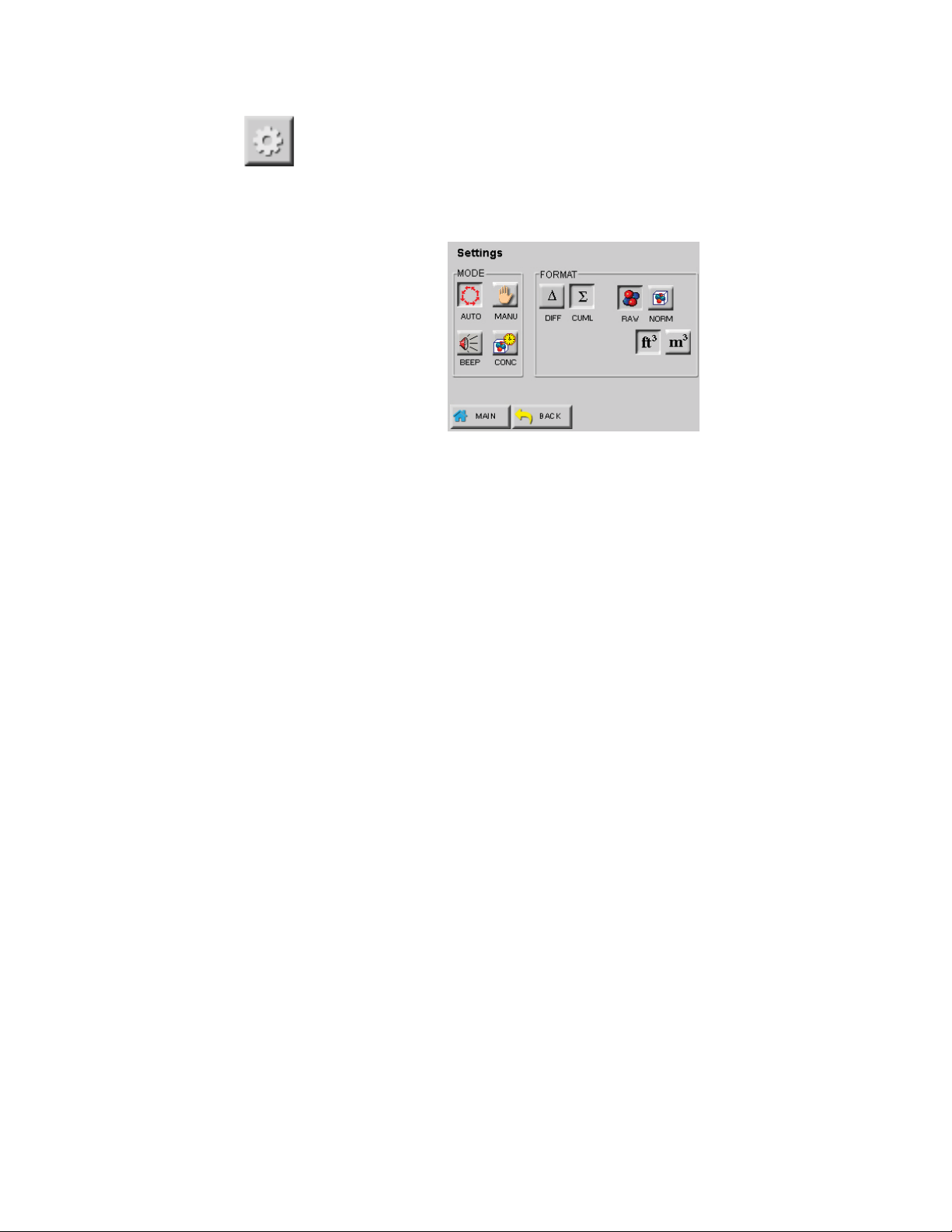
SETTING
The Settings screen allows the user to configure the instrument to count
in different modes and formats when running a sample. See Figure 5-
18.
Count MODEs
Figure 5-18 Sample Settings Screen
Note:
works with CUMULATIVE
data and for Sample Times
equal to or greater than 6
seconds.
BEEP mode only
Count modes available are Auto, Manual, Beep and Concentration.
Use of a recipe, however, overrides the display of these modes.
• AUTO - When the instrument is in Automatic Mode and the
START button is pressed, the instrument will start counting
particles automatically according to the Sample Time, Hold Time
and the number of Cycles that are configured.
If Cycles are set to 0, the instrument will continue indefinitely in
Auto Mode until the STOP button is pressed.
• MANU (Manual Mode) - When the instrument is in Manual
Mode, it will start counting when START is pressed and stop at the
end of one programmed Sample Time.
• BEEP - In this mode, the instrument is pre-configured to beep
according to the alarm threshold set in the Alarm configuration and
the instrument’s sample time when the instrument is set to collect
cumulative data. Counting starts after the START button is pressed
and the pump flow rate is stable. It will continue until the STOP
button is pressed or the number of configured cycles is reached.
If no channel is set for alarming when BEEP mode is selected, the
instrument will automatically use the smallest channel size and its
alarm threshold setting to alarm.
If alarming is enabled on more than one channel when the
instrument is in BEEP mode, it will beep if the alarm threshold is
exceeded on any of the channels enabled for alarming.
5-14 248083440-1 Rev 5

Operate the ApexPortable
Note: If BEEP mode is
set to one count, each
beep may not be for every
single count.
Note:
for Auto, Manual and Beep
modes count down and the
sample times for
Concentration mode count
up.
The sample time
• The data will be recorded based on the set sample and hold times
and can be viewed in the View Buffer and on the printouts. There
will be no indication on the record that the data was saved while the
instrument was in BEEP mode.
• CONC (Concentration Mode) - When the instrument is in
Concentration mode, it shows the calculated concentration of
particles in a volume of air measured and displayed on the MAIN
screen in either counts per cubic foot or per cubic meter.
Counting starts shortly after the START button is pressed and it will
continue until the STOP button is pressed or the sample time runs
out. The sample time for Concentration mode is six seconds. As the
sample time on the MAIN screen counts from one to six, the
particle counts are updated continuously.
Concentration data will be recorded and can be viewed in the Data
screen and on the printouts.
FORMAT
Instrument data is displayed as Differential (DIFF) or Cumulative
(CUML) counts. For clarity, cumulative mode shows all counts from
channel size of interest and above and displays on MAIN as .
Differential mode shows all counts from channel size of interest to next
channel size and displays on MAIN as the delta .
The data format is either Raw (RAW) or Normalized (NORM). Raw
data displays the actual number of particles counted. Normalized data
shows particle concentrations calculated from the raw data based on the
settings chosen (ft
3
or m3).
• Volume of Air = Sample time (minutes) x FlowRate (CFM)
• Normalized Data = Number of Particles/Volume of Air
Press BACK to return to the Configuration screen or press MAIN to
return to the MAIN screen.
248083440-1 Rev 5 5-15

Lighthouse ApexPortable Operating Manual
ALARM
Press ALARM button to open the Particle Alarm screen shown in
Figure 5-19 to enable alarming on specific channels.
Disable
Note: Alarming is only
applicable for Cumulative
Raw particle counts even if
the instrument is displaying
Normalized data.
If the instrument is set to
display Cumulative data,
the alarm threshold will
apply to the cumulative
counts.
press
button to
change
the alarm
threshold
Enable
Press button to
Change State
Figure 5-19 Particle Alarm Configuration Example
To enable or disable alarming for any channel, press the ICON to the
right of the channel. When the is displayed, the channel is enabled
for alarming. Press the ICON to change it to the and disable the
alarming for that channel.
Alarm Threshold
Press the enabled channel’s threshold button to set the alarm threshold
for that channel. The Alarm Threshold screen will open as shown in
Figure 5-20.
Figure 5-20 Configure Alarm Threshold
Note: To use alarms, the
Sample Time must be
greater than 1 second.
5-16 248083440-1 Rev 5
Enter the desired alarm threshold for the channel as a number of
particles then press ENTER. The threshold value will be updated on
the Particle Alarm screen.
Note:
triggered per sample
record. At the end of the
sample time, the alarm is
reset.
Note:
on two channels and the user
presses the screen to
acknowledge the alarm when
the first channel goes into
alarm, the alarm will not
sound if the second channel
threshold is reached within
the same sample period.
Alarms are
If alarms are enabled
Operate the ApexPortable
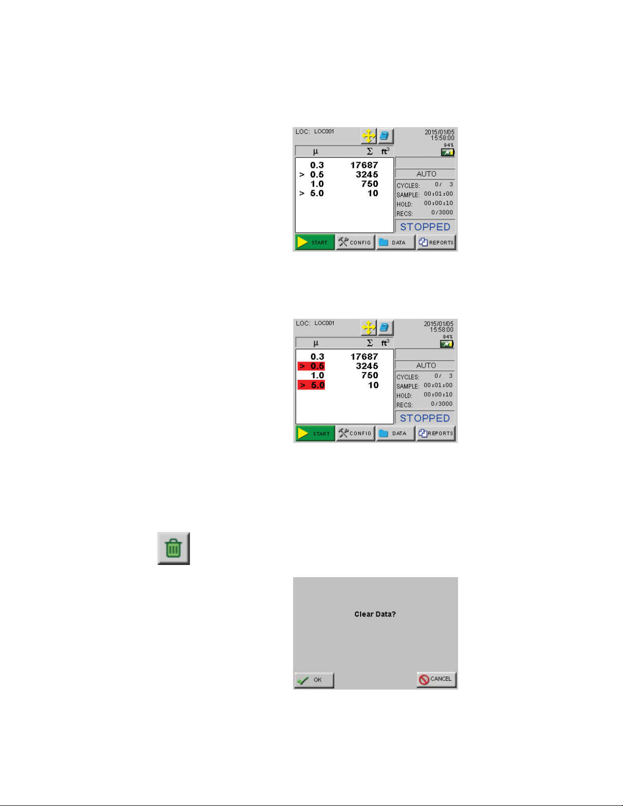
Press BACK to return to the CONFIG screen or press MAIN to return
to the MAIN screen. The alarm activated channels will display a
selection cursor (>) as shown in Figure 5-21.
Figure 5-21 Channels Enabled for Alarming
When an alarm-enabled channel goes into alarm, the selection cursor
(>) and the channel size are highlighted in red. See Figure 5-22.
Figure 5-22 Channels in Alarm
When the instrument begins to beep in response to the Alarm settings,
touch anywhere on the MAIN screen to silence the beep. The count
will be reset when the next sample cycle begins after the alarm is
acknowledged.
CLEAR
Press Clear Buffer to clear the instrument data buffer. See Figure 5-23.
Figure 5-23 Clear Buffer Screen
Press OK to clear the data or Cancel to exit the screen without clearing
248083440-1 Rev 5 5-17

Lighthouse ApexPortable Operating Manual
data.
DEVICE
SETUP
The DEVICE SETUP buttons adjust how the instrument operates when
running samples. Specific functions for display options, data output
and security can be enabled or disabled . See Figure 5-24.
Figure 5-24 Device Setup Options
CLOCK
The Date & Time screen allows the user to change the instrument’s date
and time. See Figure 5-25.
Figure 5-25 Date & Time Configuration Screen
Use the Text Window and numeric buttons to enter the Date values for
desired month, day and year then press the ENTER button.
5-18 248083440-1 Rev 5

Note:
MONTH 1ST (M / D/
Y) is the default date format.
Operate the ApexPortable
Press the M / D/ Y button to display the date as month-first. Pressing
the D / M/ Y button displays the date as day-first and the Y / M/ D
button displays the date as year-first. See Figure 5-26 and 5-27.
Figure 5-26 Date Option: Day First
Figure 5-27 Date Option: Year First
Press the TIME button to set the instrument’s time. See Figure 5-28.
Figure 5-28 Configuring TIME
Enter the desired time in hours, minutes and seconds then press
ENTER to save the new time. Press BACK to return to the
Configuration screen or press MAIN to return to the MAIN screen.
248083440-1 Rev 5 5-19

Lighthouse ApexPortable Operating Manual
OPTIONS
The Options screen allows the user to make visual and sound
adjustments as well as selecting different language formats and start-up
functions. See Figure 5-29.
Figure 5-29 Options Configuration Screen
Contrast Adjust
Adjust the contrast/brightness of the LCD screen by pressing the upper
UP and DOWN arrows.
Audible Beep Adjust
Adjust the audio level of the BEEP by pressing the lower UP and
DOWN arrows.
ALIGN Touch Screen
Align the the touch screen by pressing the ALIGN button so the
locations touched on the screen correspond to the expected function.
Alignment can also be started from a power-off state by pressing on the
screen while turning the
ApexPortable on. The start screen shown in
5-30 will be displayed at that time. The screens shown on the next few
pages will be the same, regardless of how the process was started.
• Press the ALIGN button.
5-20 248083440-1 Rev 5

Operate the ApexPortable
WARNING: Be
careful to touch the
screen at the specified
locations, only. Touching
the screen elsewhere
during this process will
align the screen
incorrectly.
Note:
Using a PDA Stylus
provides higher accuracy to
the touch screen interface.
• The screen in Figure 5-30 appears. Touch anywhere on the screen
to continue calibration.
Performing touch
screen calibration.
Touch screen to
continue.
Figure 5-30 Display Calibration Start Screen
• At the next screen, touch in the center of the cicle displayed in the
upper left corner. Release the touch to move to the next alignment
circle. The tip of a stylus is suggested to successfully complete the
alignment by being on-target more accurately than by using a finger
tip. Exercise care to prevent puncturing the screen’s membrane,
which will void the instrument warranty. Figure 5-31 shows the
second and third Calibration screens.
Press & Release
on the filled
circle.
• The fourth and fifth alignment screens are shown in Figure 5-32;
Touch as close to the center as possible.
Press & Release
on the filled
circle.
Figure 5-31 Second and Third Calibration Screens
248083440-1 Rev 5 5-21

Lighthouse ApexPortable Operating Manual
touch the center circle to continue the alignment process.
Press & Release
on the filled
circle.
Figure 5-32 Fourth and Fifth Calibration Screens
• Figure 5-32 shows the final alignment screen. Touching the filled
circles properly completes the alignment process.
Press & Release
on the filled
circle.
To REPEAT calibration
reset the board while
pressing on the screen
until the calibration
prompt appears.
Touch screen to
continue.
Note: The screen
alignment function can
also be accessed by
touching the screen when
powering the instrument
on.
Figure 5-33 Display Calibration Completed
The final screen, shown Figure 5-33, instructs the operator to Touch
anywhere on the screen to complete the process. Touch anywhere
on the screen to return to the OPTIONS screen.
Autostart Mode
Autostart mode starts the instrument sampling immediately upon
power up. The instrument will sample based on its configured mode,
delay, start and hold times.
Diff+Cuml Zoom
If Diff+Cuml Zoom is enabled, the Zoomed display will show two
columns of data simultaneously - Differential and Cumulative.
5-22 248083440-1 Rev 5

Operate the ApexPortable
One Channel
If One Channel is enabled, only the first channel will be displayed on
the MAIN screen.
Note:
is disabled, the display and
zoomed data view will be
blank.
If the first channel
One Channel mode only affects how data is displayed on the MAIN
screen. When the instrument is in One Channel mode, data will
continue to be recorded, printed and downloaded for all channels. See
Figure 5-34.
Figure 5-34 One Channel Option Enabled
One Second Realtime Modbus Output
Set One Second Real-time MODBUS Output to change the
instrument’s settings to the following:
Note:
available when One
Second Real-time
MODBUS Output is
enabled.
Note:
sample time, hold time, etc.)
is changed, the One Second
Real-time MODBUS Output
mode will be automatically
disabled.
Alarming is not
If any setting (mode,
• Mode: AUTO
• Cycles: Zero
• Sample Time: One second
• Hold Time: Zero seconds
• Cumulative/Differential: Cumulative (CUML)
• Raw/Normalized: Raw
When counting, the MAIN Screen will update continuously and data
will not be recorded in the data buffer.
248083440-1 Rev 5 5-23

Lighthouse ApexPortable Operating Manual
Language
Press the LANGUAGE button to change the operating language as
shown in Figure 5-35.
Press the button next to the desired language to change it from the
to the to enable. Press BACK to return to OPTIONS or MAIN
button to return to MAIN screen. The default language is English.
Figure 5-35 Operating Language Screen
COMM
Press the COMM to set the ApexPortable communication mode.
Press the SERIAL’s toggle button to select SERIAL mode; press the
ETHERNET’s toggle button to select ETHERNET mode.
Press
Figure 5-36 COMM-mode Setup Screens
Press the SERIAL button (Figure 5-36) to configure serial settings at
the screen shown in Figure 5-37.
to select
COMM Serial Settings
When the
system or other RS485 network, the
5-24 248083440-1 Rev 5
ApexPortable is connected to a SCADA data collection
ApexPortable’s COMM address

Operate the ApexPortable
identifies it. The communication speed must be matched to the
requirements of the network to which it will be connected or the
connection will fail. Press the button describing the setting desired to
be changed, such as ADDRESS, BAUD, etc.
Figure 5-37 COMM Serial Settings Screen
Management programs like LMS Express/RT will search for the
instrument by the COMM Address specified on the screen shown in
Figure 5-37. COMM addresses can be 1 to 63 for the ApexPortable.
Each device on a multi-port chain must have a unique address.
Note: The Data-entry
screen text box will be
empty and won’t display
the previous values so it
may be wise to write down
the previous values from
the screen shown in Figure
5-37, first.
Press the ADDRESS button to open the Address input screen (Figure
5-38) and use the numeric keypad to type the address; press ERASE to
erase a digit, if needed and ENTER to accept the value and return to the
Comm SERIAL Settings screen.
Figure 5-38 Serial Address Input Screen
Check the other values and change them by pressing the parameter
button, such as BAUD, DATA BITS, PARITY. The data entry screen
will display a window for entering the value(s) desired. Make sure the
values entered are correct for the environment / network or the
ApexPortable communications will fail. The previously set values
will not be displayed.
248083440-1 Rev 5 5-25

Lighthouse ApexPortable Operating Manual
Set ETHERNET Settings
Press COMM at the Config screen to display Figure 5-39. Press the
ETHERNET’s toggle button to change it to the green check as shown.
Press the ETHERNET button to open the COMM Ethernet Settings
screen, Figure 5-40, which is displaying the original default values.
Figure 5-39 Comm ETHERNET Mode
Figure 5-40 COMM Ethernet Settings Screen
Press a number button to open the Data entry screen (Figure 5-41).
Enter the new value then ENTER to save and return to the Settings
screen. Press BACK to return to Settings screen and lose any changes.
Press ERASE to delete one digit at a time.
Figure 5-41 IP Data Entry Screen
5-26 248083440-1 Rev 5

Operate the ApexPortable
Make sure the values are correct. Incorrect values can cause the
ApexPortable to be lost on the network. It is suggested that site IT be
consulted for the IP and other values to ensure successful integration.
Typical Ethernet settings for most networks and the
ApexPortable are
a static IP, SUBNET empty/zeroes, and default Gateway is empty.
Lighthouse recommends using a static IP adress. .
OUTPUT
The Output Setup screens (Figure 5-42) provide formatting and other
options for printing to the optional USB printer or saving the data to a
USB flash drive. The port is shown in Figure 5-43.
Printer Output
Setup Screen
USB Output
Setup Screen
Figure 5-42 Output Setup Screens, Printer and USB Set Up
USB Port for
Printer or
Flash Drive
Useage
Figure 5-43 USB Port Location
248083440-1 Rev 5 5-27

Lighthouse ApexPortable Operating Manual
Printer Output
The default Printer Output or the last chosen screen will be shown
when entering the Output Setup screen. Cumulative (with nothing else
selected) is the default selection for Printer Output. Reports can be
printed using only Cumulative or Differential enabled or with both
enabled. At least one must be selected or the instrument will choose
Cumulative. Output trigger can be either Sample or Alarm or both.
From the MAIN screen, press CONFIG button then OUTPUT to go to
one of the screens shown in Figure 5-42. If USB output is active, go to
“USB Output”.
• Model Name - prints the product model name;
• Serial Number - prints the instrument serial number;
• Separator - prints a line of dashes to separate Serial Number
from data areas;
Note:
formatted devices; an
NTFS formatted device is
not compatible with the
ApexPortable. A
corrupted device will cause
data transfer failures.
Check the formatting and
functionality on a PC or
MAC before use.
Use only FAT32
• Output on Sample - when a sample is taken, the data for that
sample is printed;
• Output on Alarm - When an alarm threshold is exceeded, a
report of that data is printed;
• Cumulative - Data is reported in cumulative format;
• Differential - Data is printed in differential format.
USB Output
When a USB flash drive is attached to the USB port, the
ApexPortable
will acknowledge its presence by displaying the blue USB symbol on
the MAIN screen. From the MAIN screen, press CONFIG button then
OUTPUT to configure the USB settings - refer to Figure 5-44.
• Output on Sample - outputs data to the USB flash drive at the
completion of a sample;
• Output on Alarm - outputs data to the USB flash drive when
an alarm is triggered;
• *.CSV - data being stored on the USB flash drive is Comma-
Separated-Value, a spreadsheet compatible format - this is the
default setting displayed for the user;
• *.LSD - Lighthouse Secure Data format is used and can be
downloaded only by LMS Express, LMS Pro or LMS Pharma.
5-28 248083440-1 Rev 5

Operate the ApexPortable
Password
Enter the
desired
numeric
here
using this
keypad
Output on Sample and Output on Alarm can be chosen together or
separately, which is the preferred choice. Either *.CSV or *.LSD must
be chosen, but not both simultaneously. If neither *.CSV nor *.LSD is
chosen, *.CSV will be the default and will not leave screen until it is
set. A message will not be displayed when the save is completed.
Records are always stored on the
Figure 5-44 Example of USB Output Options
ApexPortable in LSD.
Security
Press the Security button to enter Figure 5-45 screen. User access to
the instrument can be restricted by configuring the
two different password levels.
Figure 5-45 Security Password Configuration Screen
ApexPortable’s
248083440-1 Rev 5 5-29

Lighthouse ApexPortable Operating Manual
WARNING:
record and store the unit’s
passwords in a safe place.
If the password is lost or
forgotten, contact
Lighthouse technical
support at 1(USA Toll Free) or 1-541770-5905 (Outside of
for assistance. The
USA)
unit may have to be
returned to the factory to
reset the password.
Be sure to
800-945-5905
To restrict who can operate the instrument, enable the POWER ON
password. When POWER ON password is enabled, the correct
password will be required each time the instrument is turned on.
To restrict who can configure the instrument, enable the CONFIG
password. When the CONFIG password is enabled, the correct
password will be required before the user can access the CONFIG
screen.
• To set the password for the POWER ON, press the POWER ON
button, then type in a password using the numeric keypad. Press the
ERASE button to delete the last character, if needed.
• Press ENTER to save.
• To set the Configuration password, press the CONFIG button, then
type in a password using the numeric keypad.
• Press the ERASE button to delete the last character, if needed.
• Press ENTER to save the changes.
• Press the buttons to enable either or both passwords.
Press BACK to return to the CONFIG screen or press MAIN to return
to the MAIN screen.
Service
This section of the Configuration screen is reserved for Lighthouse
Authorized Service Providers only. The correct service password must
be entered to access this area.
STATUS Pressing the STATUS button displays the versions of each of the
Instrument’s firmware modules. Lighthouse Technical Support
personnel usually ask for this information during a support call. See
STATUS
Figure 5-46.
Figure 5-46 ApexPortable STATUS Screen
5-30 248083440-1 Rev 5

Operate the ApexPortable
RECIPE
RECIPE From the MAIN screen, press the small Recipe button to go into an
"abbreviated" menu (shown in Figure 5-47). This allows users the
convenience to access recipes without going into the CONFIG screen
or requiring a password unlock to view, load and unload a recipe.
Figure 5-47 MAIN Screen Abbreviated Recipe Screen
To edit, add or delete recipes, though, one must press the Recipe button
from the CONFIG screen to display the full Recipe setup screen. Refer
to Figure 5-48.
Figure 5-48 Recipe Setup Screen
The full Recipe screen shown in Figure 5-48 provides instrument
sampling and reports settings that are saved in a database of up to 50
recipes.
Press BACK to save the settings and return to the RECIPE screen.
248083440-1 Rev 5 5-31

Lighthouse ApexPortable Operating Manual
UNLOAD
If a recipe already exists, the VIEW button will display the settings for
VIEW
it. See Figure 5-49 and Figure 5-50. The examples shown are for USB
output with CSV file format.
Figure 5-49 Recipe - Channel Settings
LOAD
Note:
selected is already
assigned to another recipe
or if there are no available
free locations, the user will
not be able to add a new
recipe. The “Add” button
will not be displayed.
If the location
Figure 5-50 Recipe - Second Screen
Use the LOAD and UNLOAD buttons to add or remove the highlighted
recipe.
Press the ADD button to display the RECIPE name screen shown in
Figure 5-51. The recipe may be named using up to 12 characters.
Figure 5-51 Recipe Name Screen
5-32 248083440-1 Rev 5
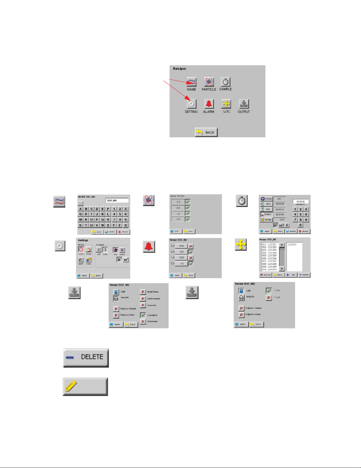
Operate the ApexPortable
Recipe Option
Choose one to
go to one of the
screens shown in
Figure 5-53.
to change
flow or other
parameters
to set alarm
thresholds
and turn alarms
ON and OFF
to select or
change location
the recipe uses
for counts
Printer
to select various print options
such as Model Name, Serial
Number and print triggers
such as Output on Sample
USB
to select save options such as
file type and save triggers
such as Output on Sample
To add the recipe to the database, press ENTER. The recipe CONFIG
screen is then displayed as shown in Figure 5-52.
Figure 5-52 Recipe Configuration
Press the option/function buttons shown in Figure 5-52 to open the
feature’s corresponding screen shown in Figure 5-53. At each screen,
choose the feature buttons desired to set up how the Location’s output
will appear in reports or in files saved.
to change the
recipe name
248083440-1 Rev 5 5-33
EDIT
to choose the
active sampling
channels
to set Cycles,
Delay, Sample
Time and
Vol ume
Figure 5-53 Recipe - Output Setting Screens
Use the DELETE button to delete any highlighted recipe from the
database.
Press The EDIT button to change a highlighted RECIPE settings. If the
ApexPortable has the recipe loaded, it will prompt the user for
permission to UNLOAD the recipe. Once it is unloaded, the user must
press the EDIT button, again, to display the EDIT screen.

Lighthouse ApexPortable Operating Manual
LOCATION The ApexPortable allows up to 200 different locations and associated
alphanumeric labels.
Press the LOC button on the CONFIG screen to display the Select
Location screen as shown in Figure 5-54.
Figure 5-54 LOCATION Setup Screen
On the Select Location screen, the Location name can be selected by
pressing the UP or DOWN arrows or by pressing the location name on
the screen.
• When enabled, the AUTO INC option automatically selects the
next location after completing the current location’s number of
cycles. After initial power up, the default is AUTO INC OFF, as
shown in Figure 5-54.
•The
ApexPortable can be configured with a maximum of 200
Locations. Each location name may be a maximum of 8 characters.
• Locations associated with recipes are denoted by asterisks (*) to the
right of the location names.
• When selecting a location that has an associated recipe, the user is
prompted to load the recipe (as shown in Figure 5-55). If the user
chooses to not load the recipe, the location can be used with the
instrument current settings.
Figure 5-55 Location - Load Recipe
5-34 248083440-1 Rev 5

Operate the ApexPortable
EDIT
• If a recipe is loaded and a location is selected that is not associated
with a recipe, the user is prompted to unload the current recipe. If
the user chooses to keep the loaded recipe, the location will adopt
the current recipe settings.
To edit a location name, press the EDIT button to display the Edit
screen shown in Figure 5-56.
Figure 5-56 LOCATION Name Edit Screen
• Enter the name of the location using the alphanumeric and
underscore keys.
• Press the ERASE button to erase the last character typed, if needed.
• Press ENTER when done.
• Use the Arrow keys to go to the next location to be edited and press
the EDIT button. Continue in the same way to edit as many
Locations as desired.
Press the BACK button to return to the CONFIG screen or the MAIN
button to return to the MAIN screen.
Press the AUTO INC button to enable automatic incrementing to the
next location after completing the number of cycles for the current
location. See Figure 5-57. This eliminates the need for the user to
manually change the location.
Figure 5-57 Auto Increment Prompt
248083440-1 Rev 5 5-35

Lighthouse ApexPortable Operating Manual
• ApexPortable will prompt the user, "Move to LOC***?", as
shown in Figure 5-57. A ’Yes’ response allows the instrument to
change location to the next.
• If the current location is using a unique recipe, the user will be
prompted if OK to unload the recipe before changing to the next
location. If the user presses ’YES’, it will unload the recipe.
• If the response is ’NO’, the instrument will use the current
recipe and switch location.
• If the new location is associated with a different recipe or
report, the
If the response is ’YES’, the recipe/report associated with the
new location will be loaded.
• If the user presses ’NO’, it will continue to use the current
recipe to sample the next location. Regardless, the user must
press the
sampling.
ApexPortable will prompt to load the new recipe.
ApexPortable MAIN screen Start button to continue
Remote
Operation
Data View
Buffer Screen
The ApexPortable can be remotely operated by the different LMS data
retrieval and facility monitoring software products, such as LMS
Express RT, LMS Net, LMS Professional and LMS Pharma. Remote
data retrieval via these products is easy and can be automated with
warning levels and alerts programmed to notify specific users or other
facilities. Visit www.golighthouse.com or contact Lighthouse Sales for
additional information and details.
Data stored on the instrument is viewed in the Data View Buffer. New
records overwrite the first records stored after the buffer fills to its limit
(3000 records). An asterisk (*) next to the word "Records" on the
MAIN screen indicates the Buffer is full and data has wrapped. The
first record shown in the Data View Buffer after data has wrapped will
be the most current record and not the first record stored. In this case,
older data will be lost if it hasn’t been printed or transferred to a PC or
management system.
Particle concentration data displays and prints in ft
Volume is set to ft
liters, data displays and prints in m3 (cubic meters).
3
(cubic feet). If the Particle Volume is set to m3 or
3
if the Particle
5-36 248083440-1 Rev 5

Operate the ApexPortable
DATA
Press the DATA button on the MAIN screen to display the Data View
Buffer.
Depending on the sample setting configuration, the data displays in
either RAW data mode as shown in Figure 5-58 or NORMALIZED to
3
ft
or m3 as shown in Figure 5-59.
Figure 5-58 Data Screen - RAW Data
Note:
has wrapped, the record
that is first displayed in the
Data screen is the last
record in the data buffer.
This may not be Rec#1.
If the single down arrow
button is pressed once, the
instrument will display the
last record in the data
buffer.
When the buffer
Scroll through the data using the UP and DOWN arrow buttons.
The single arrow moves one record at a time.
Figure 5-59 Data Screen - Normalized Data in ft
3
The Data screen displays the following information for each data
record.
• Rec # - Identifies which record is currently viewed.
• *Recs - Displays how many records are currently stored in the
ApexPortable’s buffer. An asterisk (*) next to the word "Recs"
means that the 3000 record data buffer has wrapped and older data
is being overwritten. The basic concept is First In, First Out
(FIFO).
• Size - Lists the channel sizes used for the report.
248083440-1 Rev 5 5-37

Lighthouse ApexPortable Operating Manual
• Diff, Diff / ft3, Diff / m3 - Indicate that each channel size’s data is
displayed in differential mode. If a channel was disabled, then there
is a blank space in its column; # indicates raw counts; ft
indicate normalized counts.
• Cuml, Cuml/ft3, Cuml/m3 - Indicates that each channel size’s
data is displayed in cumulative mode. If a channel was disabled,
there will be a blank space in this column. # indicates raw counts
while ft
3
• Loc - Indicates the location at which the data record was recorded.
The Location name listed is the alphanumeric label that was saved.
• Smpl - Indicates the Sample Time (HH:MM:SS) at which the data
record was sampled.
• Date - Indicates the instrument date on which the data was
recorded. The date will display in the format selected in the
configuration (MM/DD/YYYY, DD/MM/YYYY or YYYY/MM/
DD).
• Time - Indicates the instrument time at which the data was
recorded (HH:MM:SS).
and m3 indicate normalized counts.
3
and m3
• Instr - Indicates the state of the instrument at the time the data was
recorded. Instrument states include GOOD or SRVC.
• Flow - Indicates the flow state of the instrument at the time the data
record was recorded. Flow is recorded as OK or ALRM. If the flow
was in alarm, it will print as Flow: Alert on the printouts.
• Alarm - Indicates (NONE or YES) if the data record exceeded any
of the alarm thresholds of any of the channels that were enabled for
alarms. If the data record exceeded alarm thresholds, printouts
show "Alarm: Yes".
Laser - Indicates the status of the laser at the time the data record
was recorded; possible laser states include OK or SRVC. If the laser
needs to be serviced, it will print as Laser: Service.
If SRVC appears, printouts will say “Service Required”; the sensor
may need cleaning or repair. Please contact Lighthouse Technical
Support at 1-800-945-5905 (USA Toll Free) or 1-541-770-5905
(Outside of USA).
5-38 248083440-1 Rev 5

Output Data Output Data to USB Printer
Figure 5-60 USB Printer Attached
1. From the MAIN screen, press the PRINT button (shown in Figure
5-60); the printer will print the record shown on the display,
example contents shown in Figure 5-61. Formatting of the
printout is based on the settings established via the Printer
OUTPUT screen settings.
Operate the ApexPortable
Figure 5-61 Sample Current Record Print
Output a Range of Records to USB Flash Drive
Figure 5-62 Flash Drive Attached, USB Mode
248083440-1 Rev 5 5-39
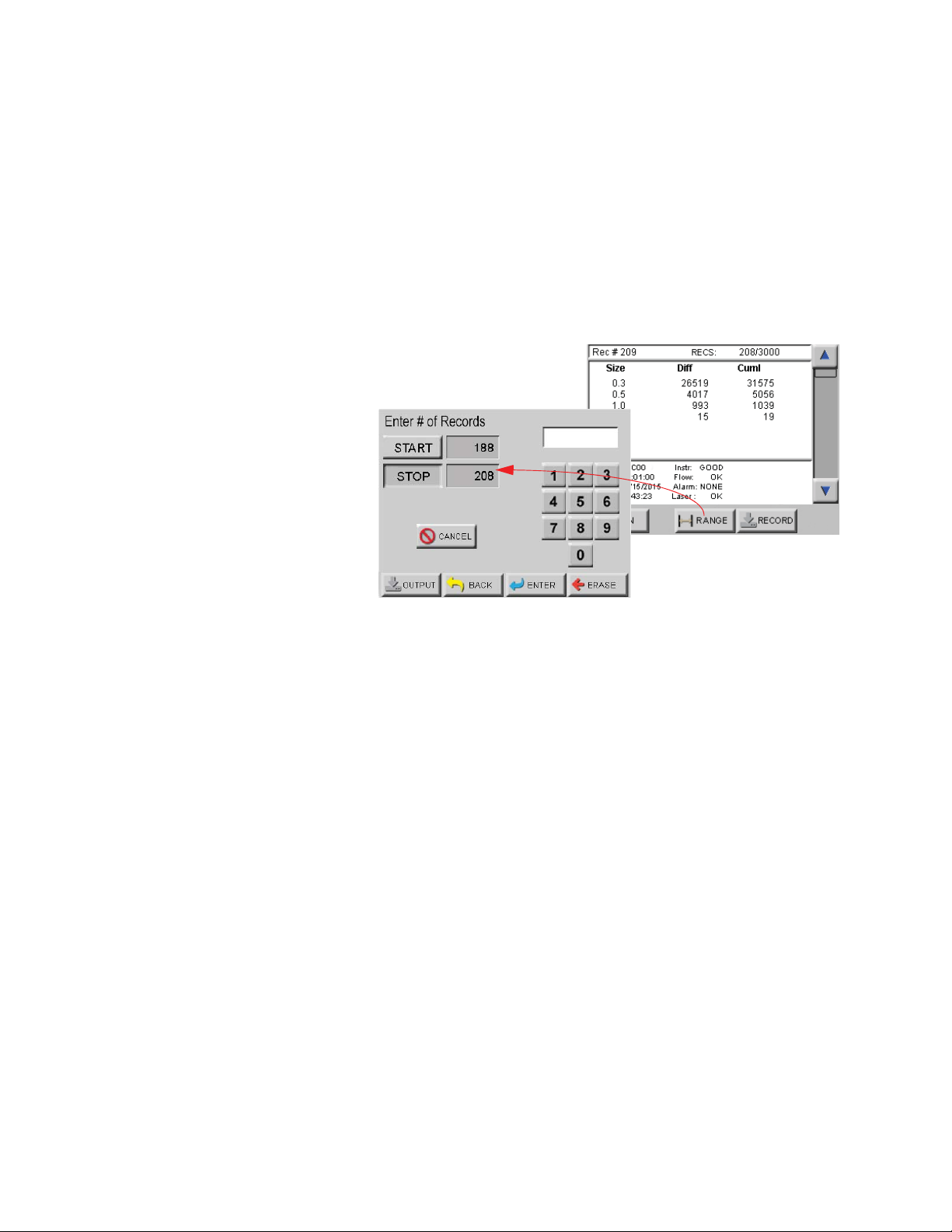
Lighthouse ApexPortable Operating Manual
1. From the MAIN screen, press the DATA button and display the
desired "start" record by using the UP and DOWN arrows to
move the list. Note the ending record desired.
2. Press the Range button to display the # of Records screen to
select a range of records to output. Figure 5-63 shows the Data
records and the range-select screens. Note that the value in
"STOP" is 208 - this is the total of records so far in this example.
If the entire list is to be stored, leave the default values and press
the OUTPUT button.
Figure 5-63 Selecting a Range of Data
3. If only a set number of records are to be saved, press the START
button and enter the first record’s number and press ENTER. If a
character is mis-typed, press ERASE to remove it. Press the
STOP button and enter the ending record to be stored. Figure 563 shows an example where 21 is the total number of records to
be stored (1st=188, end=208, difference=21, which includes 188).
When the correct numbers are entered, press the OUTPUT button
to send the records to the USB. If an incorrect value is entered,
the instrument will do nothing.
4. Records Sent will be displayed on the screen when the transfer
takes place. If the USB flash drive is not installed, NO USB will
be displayed.
Each .csv file is managed separately and is added to the flash drive
while the flash drive is attached. Because the filename is a function of
date and time, no database is kept. These ’csv’ text files can be read on
any computer system.
LSD files are securely encoded data files, the other type of file that can
be stored by the
5-40 248083440-1 Rev 5
ApexPortable on the USB flash drive.

Operate the ApexPortable
Both file types supply the same data except for Status, which applies
only to LSD format; the files contain the following information:
• Model Name:
• Serial Number:
• Flow Rate:
• Data Records including:
• Sample Date / Time Stamp
• Status (LSD format, only)
• Location
• Number of Samples
• Sample Volume
• Particle Channel Data
LSD files require LMS Express to decrypt the information stored.
LMS Express provides a new feature that allows the data from an LSD
file to be imported into LMS Express. See Figure 5-64.
Figure 5-64 LMS Express LSD File Import
When a USB flash drive is attached to the ApexPortable, the USB
symbol will display as shown in Figure 5-62.
248083440-1 Rev 5 5-41

Lighthouse ApexPortable Operating Manual
Report Requirements
Fed Std ft
3
This report requires a minimum of 2 locations be measured, at least 1
sample be taken per location and at least 5 samples total be taken in
each cleanroom at a minimum sample volume of 0.1 cubic feet.
The 95% Upper Confidence Limit (UCL) will be calculated by the
ApexPortable if the number of sampled locations is equal to or less
than 9.
Air flow (Unidirectional vs. Non-unidirectional) will have an effect on
the minimum locations and minimum samples required. In general, the
Non-unidirectional option requires more of both locations and samples.
For the Fed Std ft
3
report, the classification for a particle size is based
on its samples taken from all locations in the cleanroom. Each particle
size is given one of the following results:
• a classification rating which will be one of the possible
classifications (1, 10, 100, 1000, 10000, 100000)
• “Unable to Classify” if it fails one of the above requirements
Note:
The EU GMP 2009
report is only valid if the
instrument is configured with
the 0.5 and 5.0 micron
channel sizes and these sizes
are active.
• an “Out of Range” if the calculated classification at that particle
count exceeds 100,000
ISO 14644-1
The ISO14644-1 standard requires a minimum 60 second Sample Time
for each sample recorded.
EU GMP 2009
The EU GMP Standard Report requires the unit has the channel sizes
0.5μ and 5.0μ as these are the only channels that apply to this standard.
The EU GMP Report has different concentration limits for cleanroom
status “At Rest” versus “In Operation”. When the cleanroom is “In
Operation”, Class D is not available because the standard is not defined
for Class D in an operational cleanroom.
5-42 248083440-1 Rev 5

Note:
Apex for a minimum volume,
and takes the exact number of
minimum locations and
samples, the user could get a
“Cannot Classify: too few
locations” error if the minimum
volume rounds the sample
time down so that not enough
samples at the minimum
volume are taken.
In this case, add one or two
seconds to the sample time
so that the volume is over the
exact minimum volume.
If the user sets the
Operate the ApexPortable
REPORT FEATURE
Enable the Report Feature by pressing the (Default setting)
located at the top left of the screen. The check mark indicates the
feature is enabled, which enables the PRINT MODE status on MAIN
screen. See Figure 5-65 and 5-66.
Report
Feature
Enabled
Figure 5-65 Typical Reports Screen
• When the REPORT mode is enabled, the currently selected report
type and minimum required samples will be displayed on the
MAIN screen as shown in Figure 5-66.
Figure 5-66 Report Mode Status
• Depending on the report’s requirements, the number of cycles and
minimum sample time will be calculated when the REPORT mode
is enabled.
• The number of required locations will be automatically assigned to
the report. The user may change the locations via the report’s
SETUP screen.
• In this example the display format will be changed to Normalized
and area measurement to ft
3
for FED-209 and m3 for ISO and EU
GMP. The user may change the display mode in the Reports
Settings screen.
• The instrument keeps track of and will display on the MAIN screen
the number of samples taken for the report.
248083440-1 Rev 5 5-43

Lighthouse ApexPortable Operating Manual
• If Auto Increment is enabled, the user will be prompted to move the
particle counter to the next assigned location after the current
location’s number of cycles are completed.
• After all of the required samples have been completed, the
instrument will prompt the user to Save the Report Session as
shown in Figure 5-67.
Figure 5-67 Save Reports Prompt
Set Up Report Room Parameters
When one of the report options buttons is pressed, the instrument uses
the current Room Area, Class Level, Air Flow and Room Status
parameters to determine the minimum number of locations, samples
and volume per channel in order to classify a cleanroom with that
standard. Use the displayed minimum values to configure the
instrument so that the minimum requirements needed to classify the
cleanroom will be met. Perform the following steps to set report
parameters:
Figure 5-68 Report Setup Step 1
• Press the desired report button then press the SETUP button shown
in Figure 5-68.
5-44 248083440-1 Rev 5

Operate the ApexPortable
• Use the Report Setup screen as shown in Figure 5-69.
Figure 5-69 Report Setup Screen
• Press the CLASS button and the Select Class screen displays as
shown in Figure 5-70. Touch the desired class so it becomes
highlighted. Press the BACK button to save and return to previous
screen.
Figure 5-70 Select Class Level
• The selected level will be highlighted in blue.
Class Levels vary based on which standard has been selected in the
PRINT REPORT field. Below are the available Class Levels, per
standard:
FED_209E ft
3
- 1, 10, 100, 1000, 10000, 100000
ISO14644-1 - 1, 2, 3, 4, 5, 6, 7, 8, 9
EU GMP - A, B, C, D (Rev 2009)
Changing the Class Level will also change the minimum number of
locations, minimum number of samples and the minimum sample
volume per channel size required to satisfy the requirements of the
chosen report.
248083440-1 Rev 5 5-45

Lighthouse ApexPortable Operating Manual
Note: If the entered Area
values needs more
locations than available, a
“Not enough locations”
message will be displayed
and the user will be asked
to enter a lesser area.
Note:
The minimum area
that can be entered is 6 ft2 or
2
.
1 m
The maximum area that can
be entered depends on the
number of locations available
on the unit.
With all 200 locations
available, the Max area that
can be entered is limited to a
5 digit value for ft2 and a 4
digit value for m2.
• Press the BACK button then the AREA button to display the Area
Set Up screen shown in Figure 5-71.
Figure 5-71 Reports Area Set Up Screen
• Touch the appropriate unit of measure (ft2 or m2) and type in the
area using the keypad. Press ENTER to display the value on the
screen.
• Press the BACK button.
• Press the STATUS button to display the Room Status screen shown
in Figure 5-72.
Figure 5-72 Reports Room Status Screen
• Press the appropriate room status (As Built, At Rest, In Operation)
followed by the BACK button.
5-46 248083440-1 Rev 5
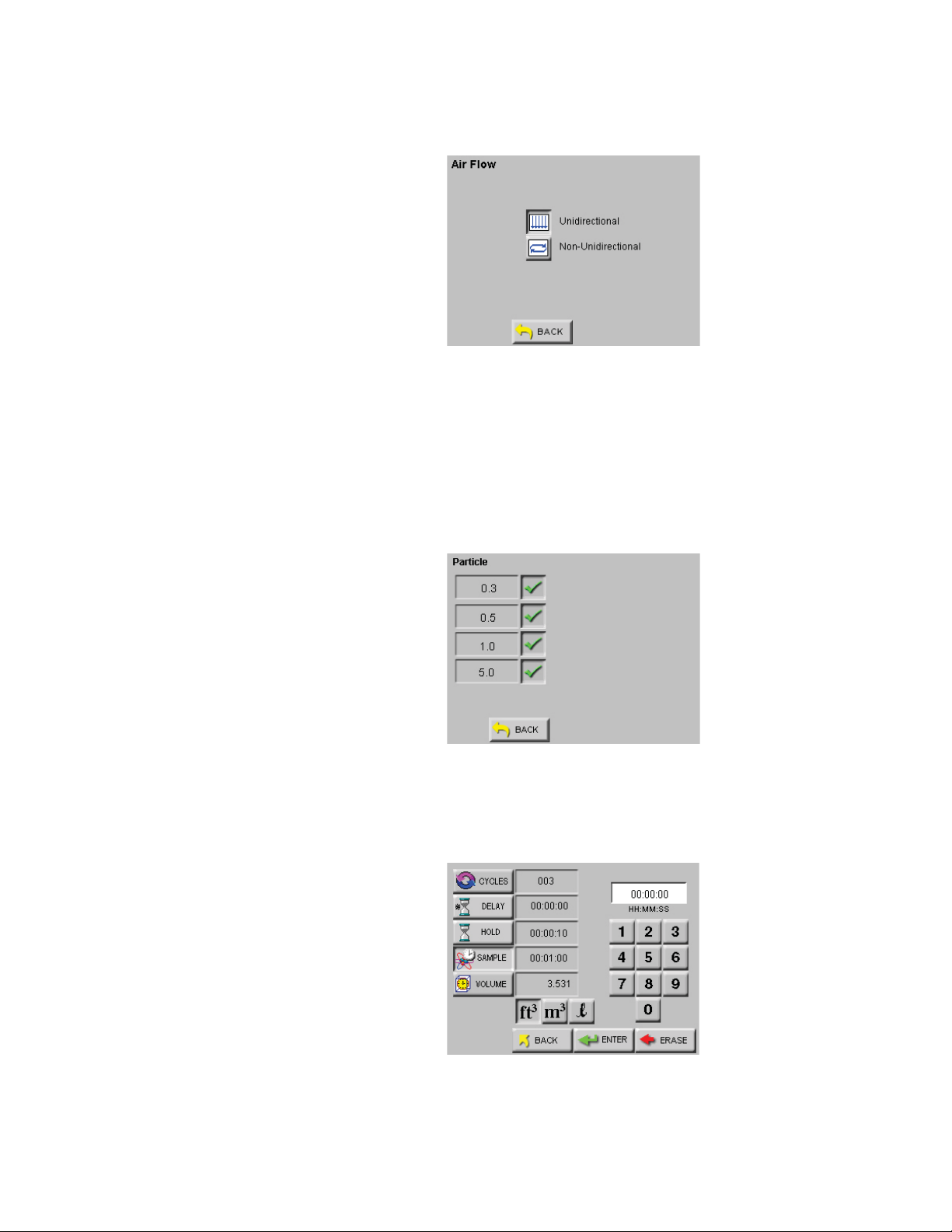
Operate the ApexPortable
• Press the FLOW button to display screen shown in Figure 5-73.
Figure 5-73 Reports Air Flow Set Up Screen
• Choose the appropriate type of air flow (Unidirectional, NonUnidirectional), then press the BACK button to return to the
SETUP screen, which will display the values that were configured
so far. Press the PARTICLE button to enable or disable particle
channels as shown in Figure 5-74 and press BACK to return to
Setup screen.
Figure 5-74 Reports Particle Set Up Screen
• Press the SAMPLE button to configure the number of Cycles,
Delay time, Hold time, Sample time and Volume. See Figure 5-75.
Figure 5-75 Reports Sample Set Up Screen
248083440-1 Rev 5 5-47
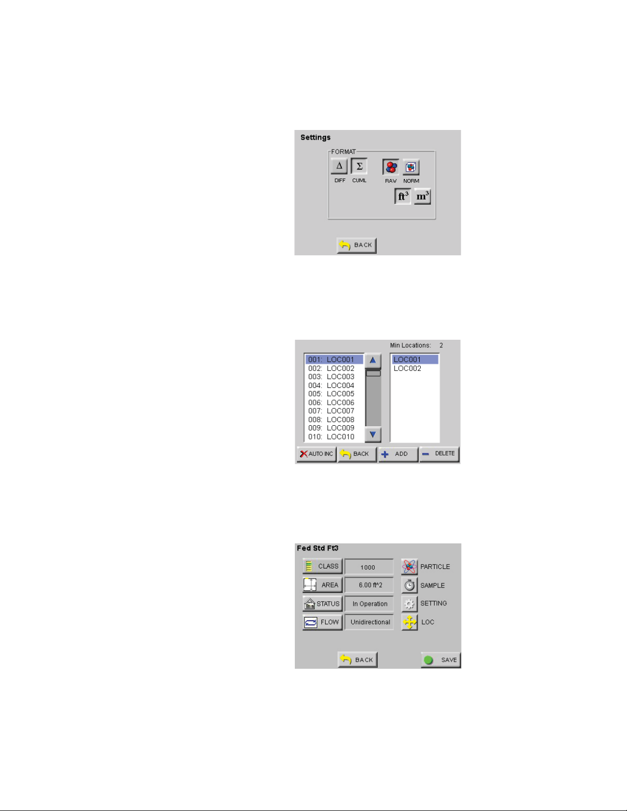
Lighthouse ApexPortable Operating Manual
• Press the BACK button then the SETTING button to format the
instrument for CUML/DIFF, RAW/NORM, ft3/m3 as shown in
Figure 5-76.
• Press BACK then LOC to select, add or delete locations or enable
AUTO INC as shown in Figure 5-77.
Note: If the location is
already assigned to
another recipe or if there
are no available free
locations, the user will not
be able to add a new
recipe. The "ADD" button
will not be displayed.
Figure 5-76 Reports Set Up Screen
Figure 5-77 Reports Location Set Up Screen
• Press BACK to return to the main REPORTs screen and SAVE to
save the configuration in the Recipe database. See Figure 5-78.
Figure 5-78 Reports Set Up Screen
5-48 248083440-1 Rev 5

Operate the ApexPortable
• When "REPORT" is enabled, the "LOC" and "SAVE" buttons are
displayed only when there are at least the minimum number of
locations needed for the recipe area available.
• If REPORT is not active or the number of locations do not meet the
minimum needed in setup, the LOC and SAVE buttons are not
displayed. See Figure 5-79.
Figure 5-79 Report Setup Screen - No Locations
The next section contains an example of setting up the instrument to
run a report.
Set Up Counter to Run Reports
For this example, the FED STD FT3 report will be used. See Figure 5-
80.
Figure 5-80 FED STD FT3 Report Screen
• Set the instrument for the Fed Std ft3 report, 100 ft2, Class 100,
unidirectional air flow, In Operation room status.
• This will generate the following minimum requirements:
• Min Locations: 2
• Min Samples: 5
248083440-1 Rev 5 5-49

Lighthouse ApexPortable Operating Manual
Note:
The Minimum
Volumes are measured in the
standard measurement
required by each specific
report.
The number of digits allowed
for area to calculate volume is
limited to a 5 digit value for ft2
and a 4 digit value for m2.
Table 5-1 Minimum Volume per Channel Size
Based on the minimum requirements displayed in Table 5-1, configure
the instrument as follows:
• Press MAIN to return to the MAIN screen.
• Press CONFIG to enter the Configuration screen.
• Press SAMPLE.
Note:
The Sample time
automatically changes to
31:42 (31 minutes, 42
seconds).
• Press the CYCLES button.
• Set the CYCLES value for 1 and press ENTER. Note that the
instrument beeps twice and clears the value. This is intentional as
the minimum cycles is 2 and changing to 1 will cause errors.
Entering more than 2 will work, though, if needed.
Ch Size (μ)Min Vol (ft3)
0.3 0.100
0.5 0.200
1.0 0.919
5.0 31.698
Note:
This is all that is
needed to meet the minimum
requirements to classify the
report.
Increase any of the
configuration parameters in
order to meet additional
reporting needs.
• Once the primary settings of Class and Area are entered, the values
are set for sample time/volume and cycles. Unless required by
SOP, there is no need to change these other values.
• Make sure to add the needed locations and press BACK.
• Press the MAIN button.
• Press START and allow the instrument to record the required
sample(s) at the first location.
Figure 5-81 Prompt to Change LOCation
• When it has finished, it will prompt to change to next location; a
YES response will change the Location but the user must press the
START button when set up and ready in the next Location.
• Move the instrument to the second location and press START.
5-50 248083440-1 Rev 5

Operate the ApexPortable
• Continue to move the ApexPortable to each location so it may run
the necessary samples, responding ’YES’ to the move prompts and
pressing START to sample at new locations.
• After the instrument finishes recording at the last location, the
instrument is ready to print the report.
Save Report
Reports are generated as "Report Sessions". All report parameters and
calculated data are stored in these sessions internally on the
ApexPortable. The files are saved as user-named Report Sessions in
user-readable format.
Figure 5-82 Saving Report Session
After completing a report session, the user will be informed if the
Report Session passed or failed and prompted if the user would like to
save the report. Saving the report allows the user to print the desired
report(s) at a later time or remotely by connecting to its web page. The
file name can imply the Report Session purpose and will make it easier
to identify, such as, "FED_STD_1" or "LOAD_ EU_GMP_4".
Figure 5-83 Report Name Save Prompt
Reports can only be printed by using an external USB printer or using
the instrument’s Web Server to load the saved report from the
ApexPortable. The Ethernet-configured ApexPortable’s internal
Web Server allows the user to view any of its stored Report Sessions
through any web browser by typing the ApexPortable’s IP address.
Report Sessions can be printed as easily as one would print any web
page.
248083440-1 Rev 5 5-51

Lighthouse ApexPortable Operating Manual
Data and settings cannot be changed via the instrument web page. The
ApexPortable must be set up using the Ethernet interface and correct
IP for the network in which it is installed. Serial-configured (RS485
LAN) ApexPortable instruments do not support the web page feature.
The web page feature requires a valid TCP/IP address to be assigned to
the
ApexPortable.
Generate a Report From Data
Figure 5-84 Reports Main Screen
From the MAIN screen, press REPORTS.
1. Select the Report desired: FED STD FT3, ISO 14644-1 or EU
GMP 2009.
2. Press REPORT ENABLE to turn on green check (Figure 5-84).
3. Press the REPORT button, which will display the saved reports
list.
Figure 5-85 Reports Screen
4. Press ADD, which displays the Data View Buffer screen.
5-52 248083440-1 Rev 5

Operate the ApexPortable
5. Choose the record (for a single record print) or records by using
the RANGE button to select the records to be printed.
Figure 5-86 Entering Records Screen
6. Press the SAVE button to save the Report. Label it so its
configuration is easily understood.
Figure 5-87 Save Report Prompt
7. The ApexPortable will validate the data and display a REPORT
PASS or FAIL and prompt the user if it should be saved (Figure 5-
87). Reply, "YES".
1_RECORD
Figure 5-88 Filename Entry Screen
8. The screen for entering a filename is displayed. Label the Report
so its configuration is easily understood and press ENTER.
248083440-1 Rev 5 5-53

Lighthouse ApexPortable Operating Manual
1
st
2
nd
3
rd
4
th
9. Press the REPORT button.
10. Choose the Report name just saved and press PRINT.
Figure 5-89 Reports Screen, New Report Showing
11. If no USB printer is attached, the ApexPortable will report "NO
USB".
Printing a Previously Printed Report
To print a Report Session (see Figure 5-90), choose a report format by
pressing REPORTS then enable the REPORT check box and choose a
report format. Press the REPORT button then select a previously saved
report. Press the PRINT button and the report will print to the USB
printer.
Figure 5-90 Print a Previously Run Report
The optional USB printer must be installed or the ApexPortable will
present the error message, "NO USB". The report can also be printed
from a PC by using the
ApexPortable’s Web Server. Locate the report
and print to any printer attached to the PC.
5-54 248083440-1 Rev 5

Operate the ApexPortable
Web Reports Interface
The
ApexPortable has a Web Server that allows the user to view its
data in real time and print reports from the web page’s Reports tab (see
Figure 5-91 through 5-93). The instrument must be set up on an
Ethernet LAN to have this feature work. The PC locating and printing
these reports must be connected to a LAN that has access to the
instrument’s LAN. Refer to Figure 5-36 and Figure 5-39 through
Figure 5-41 for details on LAN setup.
Figure 5-91 ApexPortable Web Data Interface
The web interface provides an almost real-time look at the data as the
ApexPortable is counting.
Figure 5-92 ApexPortable Web Status Tab
Failed
Reports
Successful
Reports
in Green
Figure 5-93
248083440-1 Rev 5 5-55
ApexPortable Web Reports Tab
in Red

Lighthouse ApexPortable Operating Manual
Web Page Reports
Examples of passed and failed reports available via the
ApexPortable’s Web interface are shown in Figure 5-94 and Figure 5-
95.
Figure 5-94 Passed Report Sample
5-56 248083440-1 Rev 5

Operate the ApexPortable
Figure 5-95 Failed Report Sample
248083440-1 Rev 5 5-57

Lighthouse ApexPortable Operating Manual
*************************
Fed Std Ft3
ApexP3
Serial #: 1412105005
Report Name: FS_26_2_D
Targeted Class: 1000
Room Area: 10.76 ft^2
Air Flow: Unidirectional
Room Status: In Operation
Minimum Samples: 5
Minimum Locations: 2
Data Start:
2015/01/26 09:55:57
Data End:
2015/01/26 10:06:59
Sample Volume: 0.100 ft^3
-----------------
Particle Size: 0.3
Loc Samples Avg Conc
LOC001 5 8003.5
LOC002 5 6524.5
Mean: 7264.0
Min: 6524.5
Max: 8003.5
Std Deviation: 1045.8
Std Error: 739.5
95% UCL: 11930.2
Min Vol: 1.467 ft^3
Concen Limit: 3007
Min Volume: 0.100
Classification: FAIL
-----------------
Particle Size: 0.5
Sample Printouts of Standard Reports
Figure 5-96, Figure 5-97 and Figure 5-98 are examples of a Federal
Standard Ft3, ISO 14644-1 and EU GMP 2009 reports.
Note:
loaded, the name of the
report session will be
printed on the report.
If a recipe is
Figure 5-96 Sample Federal Standard ft3 Report
5-58 248083440-1 Rev 5

Operate the ApexPortable
*************
ISO 14644-1:2015
ApexP3
Serial#: 1512105005
Targeted Class: 8
Room Area: 1.49 m^2
Room Stat: Operational
Air Flow: Unidirect
Min Loc: 2
Min Samples/Room: 2
Recipe: ISO TEST
----01/10/2016, 13:10:17
-----
Particle Size: 0.5
Cumulative, p/m^3
Vol Req: 2.000 L
Concen Limit: 3520000
---- Loc Samples AvgConcen
LOC001 3 8781.6
LOC002 1 12271.8
----Mean: 10526.7
StdDev: 2468.0
StdError: 1745.1
95% UCL: 21521.0
Min Vol: 28.317 L
-----
Particle Size: 1.0
Cumulative, p/m^3
Vol Req: 2.000 L
Concen Limit: 832000
---- Loc Samples AvgConcen
LOC001 3 361.2
LOC002 947.1
----Mean: 2816.3
StdDev: 187.3
StdError: 132.4
Note: If a recipe is
loaded, the name of the
report session will be
printed on the report.
.
Figure 5-97 Sample ISO 14644-1 Report
248083440-1 Rev 5 5-59

Lighthouse ApexPortable Operating Manual
Note: If a recipe is
loaded, the name of the
report session will be
printed on the report.
************
EU GMP 2009
ApexP3
Serial #: 1412105005
Targeted Class: C
Room Area: 9.00 m^2
Room Stat: Operational
Air Flow: Unidirect
Min Loc: 3
Min Samples/Room: 3
Recipe: EU GMP TEST
---- 01/10/2015, 14:12:09
-----
Particle Size: 0.5
Cumulative, p/m^3
Vol Req: 2.000 L
Concen Limit: 3520000
---- Loc Samples AvgConcen
LOC003 3 6121.2
LOC004 3 4620.3
LOC005 3 5414.9
----Mean: 5385.5
StdDev: 750.9
StdError: 433.5
95% UCL: 6642.7
Min Vol: 56.634 L
-----
Particle Size: 5.0
Cumulative, p/m^3
Vol Req: 2.000
Concen Limit: 29000
---- Loc Samples AvgConcen
LOC003 3 553.3
LOC004 3 253.1
Figure 5-98 Sample EU GMP Report, Revision 2009
The preceding printouts are samples and require the
optional USB printer to be attached in order to print.
5-60 248083440-1 Rev 5

Operate the ApexPortable
Power
Shutdown
Levels
When the instrument is powered only by its rechargeable battery, a
Power Shutdown feature protects the battery from discharging
completely. A complete discharge can damage the battery. It is not
recommended to allow the battery to discharge completely. The battery
levels are displayed in Table 5-2.
Table 5-2 Levels of Battery Life
Battery
Icon
FULL
75%
50%
Description
25%
20% The battery ICON will flash to indicate the
charge is getting low.
Empty; at this level, the instrument will begin to
beep and will display "BATT LOW!" on the main
screen. It is recommended to connect to the
Power Supply, attach AC cord and plug it into an
outlet at this level.
Pump Shutdown: battery level of 5% or lower, if
the instrument is sampling, the pump will turn off.
Any attempt to start or restart the instrument will
produce a popup battery low screen then shut
down.
248083440-1 Rev 5 5-61

Operate the ApexPortable
248083440-1 Rev 5 5-62

00
6 Maintenance
Procedures
Introduction This chapter provides routine maintenance instructions for the
ApexPortable.
The maintenance procedures described in this chapter are not required
on regular or prescribed intervals and should be performed only if the
user has reason to question the data they are receiving.
Safety Before performing any of the maintenance tasks described in this
chapter, read Chapter 1 of this manual and become familiar with the
warnings and caution labels.
Maintenance Calibration
To maintain optimum performance of this instrument, it should be
recalibrated annually by a Lighthouse Authorized Service Provider.
Zero Count
Test
This section provides the user with the particle counter zero count test
procedure. A purge filter must be attached to the instrument and four
(4) five (5) minute samples must be taken. There shall be no more than
1 count during the four sample runs.
1. Start with the instrument OFF.
2. Connect the Purge filter to the sample inlet.
3. Apply power to the instrument.
4. Configure the unit to sample for 30 minutes.
5. Run a 30-minute sample period. This time allows the unit to
warm up and purge any residual particles that might be inside it.
6. Configure the unit to sample for 5 minutes with a 10-second hold.
7. Set Cycles to 4 so the instrument will take 4 5-minute samples.
248083440-1 Rev 5 6-1

Lighthouse ApexPortable Operating Manual
8. Run the test.
9. If more than one count is reported during the four five-minute
samples, allow the instrument to sample for 30 minutes to purge it
then repeat the test. If the second run fails, contact Lighthouse
support.
10. After the instrument has met the requirements of the Zero Count
test, return the instrument to its normal location and operating
status.
Fault Isolation If the instrument does not pass the Purge Count test, perform the
following procedure:
1. Check the data over the last 6 five-minute sample times.
2. If sporadic counts are occurring over all channels, the unit may
still have particles inside it. Allow the unit to sample overnight
with the purge filter attached before retesting it. If the counts are
still high after the overnight purge, call Lighthouse Technical
Support for assistance.
3. If the data shows consistent counts in the smallest channel only,
the instrument may have electrical problems and may need to be
returned to Lighthouse. Call a Lighthouse Service Representative
for assistance.
6-2 248083440-1 Rev 5

00
7 Program with the
MODBUS Protocol
General Info The ApexPortable family of instruments can be programmed using
the MODBUS Protocol. The full protocol, as used, is detailed in
Appendix A: “ApexPortable MODBUS Register Map v1.50” on
page A-1.
This chapter contains the information needed to program the basic
configuration for the instrument using the MODBUS protocol.
Protocol
Settings
Power On/
Auto Start
Note:
starting of the sampling
accommodates systems
that do not send a START
command, but just polls
the instrument for its data.
The automatic
The MODBUS Protocol is defined through an RS232 or RS485
interface with:
• Baud Rate: 19200
•Data Bits: 8
• Stop Bits: 1
• Parity: None
• Flow Control: None
When powering up the instrument, it will begin sampling using the
default configuration:
• Sample Time = 60 seconds
• Hold Time = 0 seconds
• Alarm Channel = Disabled
To stop the sampling, send the command 12 to command register
40002.
Stopping the sampling will set the Device Status bit in Register 40003
to 0.
Running the
The applicable action commands are displayed in Table 7-1.
Instrument
Using
MODBUS
248083440-1 Rev 5 7-1

Lighthouse ApexPortable Operating Manual
Val ue Ac ti on
1 Saves all writable 4xxxx register values to the EEPROM.
3 Clears the Data Buffer. Record count is set to zero.
4 Saves the instrument parameters in the 40xxx registers to
11 Instrument Start (Automatic Counting).
12 Instrument Stop.
Table 7-1 Action Commands
the EEPROM. Parameters include Sample Time, Hold
Time, and Location.
Uses defined Hold Time and Sample Time. Instrument
executes samples and holds until an Instrument Stop
command is issued.
Aborts current sample. Stops data collection.
Each of the described action commands above are written to the
command register (40002).
AUTOMATIC Counting Mode
In Automatic counting mode, the instrument uses the configured
sample time and hold time to record samples.
The instrument will continue running samples at the configured sample
time until it receives a stop command. When the stop command is
given, any partial data will not record to the buffer.
After setting all the instrument parameters as described in “Changing
the Default Instrument Parameters” on page 7-4, write these commands
to the Command register (40002):
11 Start Instrument; to start recording
12 Stop Instrument; to stop recording
7-2 248083440-1 Rev 5

Program with the MODBUS Protocol
Configuring
with the
MODBUS
Protocol
Register Data Type Description
Setting the Real Time Clock
The Real Time Clock (RTC) can be read in registers 40027 and 40028
as shown in Table 7-2.
Register 40027 is the high word for the real time clock; 40028 is the
low word. The date/time is calculated as the number of seconds since
midnight of 1/1/1970.
The date & time is stored in a 4-byte unsigned integer or as a 32-bit
unsigned integer.
Table 7-2 Real Time Clock Registers
40027 unsigned integer Real Time Clock (RTC) [high]. Works in
conjunction with 40028. Displays date and
time, in number of seconds since
midnight, 1/1/1970.
40028 unsigned integer Real Time Clock [low]
In order to change the RTC to the current local date/time, enter the high
and low values as unsigned integers to registers 40035 and 40036
respectively, which are the Data Set registers. See Table 7-3.
Table 7-3 Data Set Registers
Register Data Type Description
40035 unsigned integer Data Set [high]. Works in conjunction
with 40036. Data entered here is applied
to the device through the command
register.
40036 unsigned integer Data Set [low]
Then write the command 13 to the command register 40002. This will
write the values in the Data Set registers (40035 and 40036) to the RTC
registers (40027 and 40028).
The Real Time Clock can also be set in the Configuration Software
Tool.
248083440-1 Rev 5 7-3

Lighthouse ApexPortable Operating Manual
Changing the Default Instrument Parameters
The main instrument parameters involved with the operation of the
ApexPortable are Location, Sample Time and Hold Time. See Table
7-4.
Sample Time and Hold Time both use 2 registers, a high word and a
low word. If the desired value for any of these parameters is less than
or equal to 9 hours, 6 minutes and 7 seconds (32,767 seconds), then
only the low word register needs to be written with the value in
seconds.
The low word register for Sample Time is 40034.
The low word register for Hold Time is 40032.
Table 7-4 Instrument Parameters
Register Data Type Description
40026 unsigned integer Location number (low)
Provides Location ID for where data was recorded.
When Smart Bracket is not used, state is read/write.
When Bracket Mode is used, the location value is
read-only in 40054-40055 and low is duplicated in
40026.
40031 unsigned integer Hold Time [high].
Works in conjunction with 40032. Number of
seconds to wait between sample periods. Max value
is 359,999, which equals 99h 59m 59s
40032 unsigned integer Hold Time [low]
40033 unsigned integer Sample Time [high].
Works in conjunction with 40034. Number of
seconds to sample. Max value is 86,399, which
equals 23h 59m 59s.
40034 unsigned integer Sample Time [low]
Using Sensor Setting Registers
Certain configuration settings can be sent to the counter through these
registers.
Sensor Setting Registers 40001 and 40003 through 40023 are protected
and should not be changed.
7-4 248083440-1 Rev 5

Program with the MODBUS Protocol
Location (Register 40026)
For Particle Counters, this value specifies the location where a sample
was recorded.
Hold Time (Registers 40031, 40032)
The Hold Time is used for pausing in between samples for multiple
cycles.
This time is specified in seconds. The maximum value is 359,999
seconds (high word: 5, low word: 32319) which is 99 hours, 59
minutes, and 59 seconds. To set the Hold Time to a value less than 9
hours, 6 minutes, 7 seconds, enter the number of seconds in the low
register (40032).
During Hold Time, the Device Status bit is 0 (Idle).
Sample Time (Registers 40033, 40034)
The Sample Time specifies the time period of each sample. This time
is specified in seconds. The maximum value of the sample time is
86,399 seconds (high word: 1, low word: 20863) which is 23 hours, 59
minutes, 59 seconds.
To set the Sample Time to a value less than 9 hours, 6 minutes, 7
seconds, enter the number of seconds in the low register (40034).
During the Sample Time, the Device Status is 1 (Sampling).
248083440-1 Rev 5 7-5

Lighthouse ApexPortable Operating Manual
Alarm and
Threshold
Registers
Alarm Enable Registers
The Alarm Enable input registers (43xxx series) shown in Table 7-5 are
read/write. All enable data items are 4 bytes long and are stored across
2 registers. Byte and word ordering is big-endian. Thus, data items are
formed by placing the high bytes in front of the low bytes. For
example:
<High Bytes><Low Bytes> = <4 Byte Data Item>
The 43xxx register series is used to determine which particle data
channels are set to ALARM ENABLE.
Table 7-5 Alarm Enable/Disable Bits
Bit Description
0 Channel Enable (0=disable, 1=enable), works
in conjunction with Alarm Enable.
1 Alarm Enable (0=disable; 1=enable), requires
channel enable, as well.
Note:
currently only works for
Particle Channels.
Alarm Enable
2RESERVED
These registers run in parallel with the data registers (30xxx series).
For example, data register 30010’s enable alarm register would be
43010. Data register 30016’s enable alarm register would be 43016.
Enabling the Alarm for a particle channel requires the channel be
enabled, as well, setting the bit in the low word of that channel. The
user can enable any or all active particle channels at a time and can set
a different alarm threshold for each.
Particle data registers for the Alarm Enable setting start at 43009 for
the high word and 43010 for the low word for channel 1. See Table 7-6.
Table 7-6 Alarm Enable Registers
Register Data Type Description
43009 unsigned int Alarm Enable for Particle Channel 1 [high]
(smallest particle size starts here)
43010 unsigned int Alarm Enable for Particle Channel 1 [low]
43011 unsigned int Alarm Enable for Particle Channel 2 [high]
43012 unsigned int Alarm Enable for Particle Channel 2 [low]
7-6 248083440-1 Rev 5
 Loading...