


a Series
c Series
e Series
Installation and operation
instructions
English
Date: 08-2014
Document number: 81337-1 1-EN
© 2014 Raymarine UK Limited
R
elease 11


Documentandsoftwarechanges
Thefollowingtablesdescribethemainchangesthathavebeenmadesincethelastreleaseofboththe
productsoftwareandthisdocument.
•Applicablesoftwareversion:LightHouseII—Release11.xx
•Applicabledocuments:81337–11(a,c,eSeries),81344–5(gSSeries).
•Applicableproducts:a65/a65WiFi/a67/a67WiFi/a68/a68WiFi/a75/a75WiFi/a77/a77WiFi/
a78/a78WiFi/a95/a97/a98/a125/a127/a128/e7/e7D/c95/c97/c125/c127/e95/e97/e125
/e127/e165/gS95/gS125/gS165/gS195.
DocumentandSoftwarechanges
Applicablechapter(s)or
DescriptionApplicableapplication
AddedsupportforCP200SideVision
TM
sonarmodule.Fishnderapplication•4.9Sonarconnection
section(s)
•Chapter19Fishnder
application
•Includedsupportfora9xanda12xGNSS(GLONASS)internal
receivers.
•Refreshrateforinternalnon-GLONASSGPSreceivershas
beenupdatedto5Hz
SupportfornewaSeriesandgSSeriesMFDvariants:
•a95/a97/a98
•a125/a127/a128
•gS195
NewAlarmManager:
•Alarmscategorizedbytype.
•View,adjustandenable/disablealarms.
GPSSet-up•InternalGNSS(GPS
/GLONASS)receiver
specication(Not
applicabletogSSeries)
•6.14GPSStatus
Allapplications
•Chapter2Documentand
productinformation
•Chapter3Planningthe
installation
•Chapter4Cablesand
connections
•Chapter8Managing
displaydata
•Chapter32Technical
specication
•Chapter33Sparesand
accessories
System•Chapter12Alarm
management
•ViewallactivealarmsandalarmHistory .
•Enable/DisableindividualDigitalSwitching(SwitchPanel
application)alarms.
•Enable/DisableindividualEnginealarms.
•AddedabilitytodisabletheWaypointarrivalalarm.
NewAutoroutingfeatureforNavionicscharts:Chartapplication
AddedMin.SafeDepthsettinginBoatDetailstoenablesupport
fortheNavionics
®
Autoroutingfeature.
TheRadaroverlayfeatureintheChartapplicationcannow
usestableCOGtoperformtheoverlayifheadingdataisnot
availableorislost.
ENGLISH
Documentnumber:81337-11
Date:08-2014
System
Chartapplication•18.11Overlays
•17.2Routes
–Autorouting
•6.13Initialsetup
procedures
–Minimumsafevessel
depth
–Radaroverlay

DescriptionApplicableapplication
Applicablechapter(s)or
section(s)
AddedsupportforHebrewUserInterfacelanguage.System
Userpreferencesettingscannowbesharedforallconnected
SeaTalk
ng
displayproducts.Whenyoumakechangesto
applicablesettings,thesamesettingswillalsobeappliedtoall
networkedSeaTalk
ng
displayproducts:
Documentchanges
DescriptionApplicableapplication
Addeddetailsonhowtotroubleshootcrosstalkinterference
whenusingSideVision
TM
sonarorsystemswithmultiplesonars,
addedtoFishnderandTroubleshootingchapters.
Fishnderchapter:
•AddedimportantsoftwarerequirementsforV10.41MFDand
V4.04externalsonarmodulesoftware.
•Added:CP200,CAM200IP,DownVision
TM
transducersand
GA150toSystemIntegration.
•SeparatedManOverboardfromAlarmschapter.
•AddedscreenshotstoMOBchapter
•9.1Languageselection
System•6.18Sharedpreferences
Applicablechapter(s)or
section(s)
Fishnderapplication•19.5Sonarcrosstalk
interference
Fishnderapplication•Chapter19Fishnder
application
N/A•3.1Systemintegration(a
Series,cSeries,eSeries)
•Systemintegration(gS
Series)
N/A•Chapter13Man
Overboard(MOB)
•RemovedSilencingMOBalarmsprocedureascoveredby
acknowledgingalarms.
ListoflearningresourcesaddedtoGettingStartedandTechnical
Supportchapters.
UpdatedEngineIdenticationsectionofGettingStartedand
Dataapplicationchapters:
•AddednewprocedureforinterfacingwithoutanECI-100.
•UpdatedEngineinterfacerequirementstable.
Updatedtransducersparestoincludefullofferingasperlatest
pricelistandincludeimagesforeachtransducer.
AddedDocumentandSoftwarechangestable(thistable)to
beginningofmanual.
UpdatedAutopilotControloverview,Fishnderapplication
overviewandChartapplicationoverviewtoincludedetailsofthe
mostpopularfeaturewithlinkstomoreinformationonhowto
usethefeatures.
N/A
•6.20Learningresources
N/A•6.16Engineidentication
N/A•Chapter33Sparesand
accessories
N/AN/A
AutopilotControl,Fishnder
application,Chartapplication
•11.1AutopilotControl
overviewandfeatures
•19.1Fishnderoverview
andfeatures
•18.1Chartapplication
overviewandfeatures
•
Softwarechanges
DescriptionApplicableapplication
GlobaldismissalofLimitationsofUse(LoU)warningscreen.
SystemN/A
WhenyouacknowledgetheLoUwarningbyselectingOK,itwill
bereectedonallnetworkedMFDs.
AddedsupportforencryptedLightHouseCharts.ChartapplicationN/A
Applicablechapter(s)or
section(s)

ForafullsoftwareversionhistoryincludingalistofapplicableMFDvariantsforeachversion,referto
AppendixFSoftwarereleasehistory.
Trademarkandpatentsnotice
Autohelm,hsb
2
,RayT echNavigator,SailPilot,SeaTalk,SeaTalk
NG
,SeaT alk
HS
andSportpilotareregistered
trademarksofRaymarineUKLimited.RayTalk,Seahawk,Smartpilot,PathnderandRaymarineare
registeredtrademarksofRaymarineHoldingsLimited.
FLIRisaregisteredtrademarkofFLIRSystems,Inc.and/oritssubsidiaries.
Allothertrademarks,tradenames,orcompanynamesreferencedhereinareusedforidenticationonly
andarethepropertyoftheirrespectiveowners.
Thisproductisprotectedbypatents,designpatents,patentspending,ordesignpatentspending.
FairUseStatement
Youmayprintnomorethanthreecopiesofthismanualforyourownuse.Youmaynotmakeanyfurther
copiesordistributeorusethemanualinanyotherwayincludingwithoutlimitationexploitingthemanual
commerciallyorgivingorsellingcopiestothirdparties.
Softwareupdates
Checkthewebsitewww.raymarine.comforthelatestsoftwarereleasesforyourproduct.
Producthandbooks
ThelatestversionsofallEnglishandtranslatedhandbooksareavailabletodownloadinPDFformatfromthewebsite
www.raymarine.com.
Pleasecheckthewebsitetoensureyouhavethelatesthandbooks.
Copyright©2014RaymarineUKLtd.Allrightsreserved.


Contents
Chapter1Importantinformation........................11
CertiedInstallation...................................................1 1
TFTDisplays.............................................................12
Wateringress............................................................12
Disclaimers...............................................................13
Memorycardsandchartcards...................................13
EMCinstallationguidelines........................................13
RFexposure.............................................................14
FCC..........................................................................14
ComplianceStatement(Part15.19)............................14
FCCInterferenceStatement(Part15.105(b)).............14
IndustryCanada........................................................14
IndustryCanada(Français)........................................14
Japaneseapprovals...................................................14
Thirdpartysoftwarelicenseagreements.....................14
Suppressionferrites...................................................15
Connectionstootherequipment.................................15
Declarationofconformity............................................15
Productdisposal........................................................15
Pixeldefectpolicy......................................................15
Warrantyregistration..................................................15
IMOandSOLAS........................................................15
Technicalaccuracy....................................................15
Chapter2Documentandproduct
information...........................................................17
2.1Handbookinformation..........................................18
2.2Handbookconventions.........................................19
2.3Handbookillustrations..........................................21
2.4Productoverview.................................................21
2.5Systemfeaturehighlights......................................25
Chapter3Planningtheinstallation...................31
3.1Systemintegration...............................................32
3.2Installationchecklist.............................................38
3.3SystemLimits......................................................38
3.4Multipledatasources(MDS)overview...................39
3.5Identifyingyourdisplayvariant..............................39
3.6Networkingconstraints.........................................40
3.7Typicalsystems...................................................41
3.8Systemprotocols.................................................44
3.9Datamaster.........................................................45
3.10a6xanda7xpartssupplied.................................45
3.11a9xanda12xpartssupplied................................46
3.12e7/e7DPartssupplied......................................46
3.13cSeriesandeSeriespartssupplied..................47
3.14Toolsrequiredforinstallation...............................47
3.15Selectingalocation............................................48
Chapter4Cablesandconnections....................51
4.1Generalcablingguidance.....................................52
4.2Connectionsoverview..........................................53
4.3a9xanda12xconnectionsoverview......................54
4.4Powerconnection—a6xanda7x.........................54
4.5Poweranddataconnection...................................56
4.6Networkconnections............................................59
4.7Keypadconnection...............................................59
4.8Radarconnection.................................................60
4.9Sonarconnection.................................................62
4.10Thermalcameraconnection................................65
4.11IPCameraconnections.......................................66
4.12Weatherreceiverconnection...............................67
4.13Fusionlinkconnection........................................67
4.14GPSconnection.................................................68
4.15GA150connection..............................................69
4.16AISconnection...................................................70
4.17Fastheadingconnection......................................70
4.18SeaTalk
4.19NMEA2000connection......................................72
4.20SeaTalkconnection............................................72
4.21NMEA0183connection......................................73
4.22a6xanda7xtoNMEA0183DSCVHFradio
connection................................................................74
4.23Camera/Videoconnection.................................74
4.24Camera/videoin-outconnection........................75
4.25Mediaplayerconnection.....................................76
4.26Bluetoothremotecontrolconnection....................77
4.27Remotecontrolfunctions....................................79
4.28WiFiconnections................................................81
ng
connections........................................71
Chapter5Mounting.............................................83
5.1Mounting-aSeries..............................................84
5.2Mounting-cSeriesandeSeries...........................86
Chapter6Gettingstarted...................................89
6.1Displaypower......................................................90
6.2aSeriesControls.................................................90
6.3e7/e7DControls.................................................91
6.4c95/c97/c125/c127/e95/e97/e125/e127/
e165Controls............................................................91
6.5Homescreenoverview—T ouchonly
displays....................................................................93
6.6Homescreenoverview—cSeries/eSeries...........93
6.7Pages.................................................................95
6.8Applications.........................................................97
6.9Splitscreencontrols..............................................98
6.10Screenoverview................................................99
6.11Basictouchscreenoperations............................102
6.12Multi-Touchgestures........................................103
6.13Initialsetupprocedures....................................103
6.14GPSStatus......................................................106
6.15Enablingautopilotcontrol..................................108
6.16Engineidentication.........................................109
6.17EnablingAISfunctions.......................................111
6.18Sharedpreferences...........................................111
6.19Softwareupdates..............................................1 12
7

6.20Learningresources............................................113
14.2EnablingDSCVHFradiointegration..................192
Chapter7Systemchecks.................................115
7.1GPSCheck.........................................................116
7.2Radarcheck.......................................................116
7.3Sonarcheck.......................................................117
7.4Thermalcamerasetupandchecks.......................119
Chapter8Managingdisplaydata....................121
8.1Memorycardsandchartcards............................122
8.2a6xanda7x.......................................................122
8.3a9xanda12x.....................................................123
8.4candeSeries....................................................124
8.5Savinguserdataandusersettings......................125
8.6Screenshots......................................................129
8.7Resettingyoursystem........................................130
Chapter9Customizingyourdisplay...............131
9.1Languageselection............................................132
9.2Boatdetails........................................................133
9.3Unitsset-up.......................................................134
9.4TimeandDateset-up.........................................135
9.5Displaypreferences...........................................136
9.6Databaranddataboxoverview............................139
9.7Listofdataitems................................................141
9.8Systemset-upmenus.........................................148
Chapter10Documentviewerapplica-
tion......................................................................159
10.1Documentvieweroverview...............................160
Chapter15Fuelmanager..................................193
15.1Fuelmanageroverview....................................194
Chapter16AISfunction....................................197
16.1AISoverview....................................................198
16.2AISprerequisites..............................................199
16.3AIScontextmenu.............................................199
16.4EnablingAIS....................................................200
16.5DisplayingAISvectors......................................200
16.6AISstatussymbols...........................................201
16.7AISsilentmode................................................201
16.8AIStargetsymbols...........................................202
16.9DisplayingdetailedAIStargetinformation...........203
16.10ViewingallAIStargets....................................203
16.11UsingAIStoavoidcollisions............................204
16.12Targetoptions................................................205
16.13AISalarms.....................................................206
16.14Buddytracking...............................................206
Chapter17Waypoints,Routesand
Tracks.................................................................209
17.1Waypointsoverview..........................................210
17.2Routes.............................................................219
17.3Tracks.............................................................227
17.4ImportandExport.............................................229
17.5Waypoints,routesandtracksstorage
capacity..................................................................229
Chapter18Chartapplication............................231
Chapter11Autopilotcontrol............................163
11.1AutopilotControloverviewandfeatures.............164
11.2Enablingautopilotcontrol..................................164
11.3Engagingtheautopilot......................................165
11.4Adjustingthecurrentlockedheading.................165
11.5Disengagingtheautopilot..................................166
11.6Manuallydisplayingthepilotcontroldialog
box.........................................................................167
11.7PilotControldialog...........................................167
11.8PilotBar...........................................................168
11.9PilotSet-up......................................................169
11.10Pilotsettings...................................................169
11.11Commissioning...............................................172
11.12Autopilotstatussymbols..................................176
11.13Autopilotalarms..............................................176
Chapter12Alarmmanagement........................177
12.1Alarmsoverview...............................................178
12.2AlarmManageroverview..................................178
12.3Alarmoptions...................................................181
Chapter13ManOverboard(MOB)...................187
13.1Manoverboard.................................................188
Chapter14DSCVHFradiointegration............191
14.1DSCVHFradiointegration................................192
8aSeries/cSeries/eSeries
18.1Chartapplicationoverviewandfeatures.............232
18.2Electronicchartsoverview................................234
18.3Navigationoptions............................................237
18.4Chartrangingandpanning................................239
18.5Chartselection.................................................240
18.6Vesselpositiononthechartdisplay...................240
18.7ChartOrientation..............................................241
18.8Chartmotionmode...........................................242
18.9Chartviews......................................................243
18.10Chartdisplay..................................................245
18.11Overlays........................................................245
18.12Chartvectors.................................................252
18.13Cartographyobjects.......................................253
18.14Objectinformation..........................................255
18.15Depth&Contouroptions.................................259
18.16MyDataoptions.............................................261
18.17Multiplechartsynchronization.........................261
18.18Measuringdistancesandbearings..................262
Chapter19Fishnderapplication....................263
19.1Fishnderoverviewandfeatures.......................264
19.2Sonartechnologies...........................................266
19.3Raymarinesonarmodules................................268
19.4Multiplesonarmodulesupport..........................268
19.5Sonarcrosstalkinterference..............................270

19.6Customchannels.............................................272
19.7Thesonarimage..............................................273
19.8DepthRange...................................................274
19.9SideVision
19.10Fishnderscrolling.........................................275
19.11Fishnderdisplaymodes.................................276
19.12SideVision
19.13Presentationmenuoptions..............................279
19.14Depthanddistance.........................................280
19.15WaypointsintheFishnderapplication............281
19.16Sensitivitysettings..........................................281
19.17Fishnderalarms............................................286
19.18Frequencytuning...........................................287
19.19Sounderset-upmenuoptions..........................288
19.20Transducerset-upmenuoptions.....................289
19.21Resettingthesonar........................................290
TM
Range........................................275
TM
Views.......................................278
Chapter20Radarapplication...........................291
20.1Radaroverview................................................292
20.2Radarscannerstatussymbols..........................293
20.3Radardisplayoverview.....................................294
20.4Radarrangeandimagequality..........................296
20.5Targettracking.................................................298
20.6Distances,range,andbearing...........................302
20.7Radarmodeandorientation..............................304
20.8Radarpresentationmenuoptions......................307
20.9
controls...................................................................310
20.10HDandSuperHDradaradjustments.................311
20.11Non-HDdigitalradomesadjustments...............313
20.12Dualrangeradaroperation.............................315
20.13Radarscanspeed..........................................316
20.14RadarSet-upmenu........................................317
20.15Resettingtheradar.........................................319
Radartuning:On-screengain
Chapter21Dataapplication.............................321
21.1Dataapplicationoverview.................................322
21.2
21.3
21.4Customizingthedataapplication.......................325
21.5Engineidentication.........................................327
21.6Settingboatdetails...........................................329
21.7SettingmaximumengineRPM..........................329
21.8Colortheme.....................................................330
21.9Unitsset-up.....................................................331
21.10Listofdataitems............................................332
21.11Resettingminimumandmaximum
readings..................................................................339
21.12Resettingalldatapages..................................339
Selectingdatapagesusingtouch................324
Selectingdatapages..................................325
22.2Thermalcameraimage.....................................342
22.3Controlsoverview.............................................343
22.4Cameracontrol................................................344
22.5Imageadjustments...........................................346
22.6Panandtiltcamera—newcamera
interface..................................................................349
22.7Highpowerandhightorquemodes...................352
22.8Panandtiltcamera—oldcamera
interface..................................................................353
Chapter23Thermalcameraapplication—
xedmountcameras.........................................357
23.1Thermalcameraapplicationoverview................358
23.2Thermalcameraimage.....................................358
23.3Controlsoverview.............................................359
23.4Cameracontrol................................................360
23.5Imageadjustments...........................................360
23.6Fixedmountcameramenu...............................362
Chapter24Cameraapplication........................365
24.1Cameraapplicationoverview............................366
24.2Cameracycling................................................367
24.3Namingcamera/videofeeds............................368
24.4Adjustingthevideoimage.................................368
24.5Selectingtheaspectratio..................................369
24.6Selectingalocationtostorerecordings..............369
24.7Recordandplayback........................................370
24.8Takingphotos...................................................371
Chapter25Fusionlinkapplication..................373
25.1Fusionlinkoverview.........................................374
25.2Mediasources.................................................375
25.3Browsingmusic................................................377
25.4Selectingshufeandrepeatfunctions................377
25.5Adjustingvolumelevelsforeachzone..............378
25.6Selectingthezonetocontrol.............................378
25.7Adjustingthetonecontrols................................379
25.8Selectingthesystemtocontrol..........................379
25.9Menuoptions...................................................380
Chapter26Weatherapplication(North
Americaonly).....................................................381
26.1Weatherapplicationoverview............................382
26.2Weatherapplicationsetup................................382
26.3Weatherapplicationdisplayoverview................383
26.4Weathermapnavigation...................................386
26.5Weathercontextmenu......................................386
26.6Weatherinformation.........................................387
26.7Weatherreports...............................................388
26.8Animatedweathergraphics...............................389
26.9Weatherapplicationmenuoptions.....................389
26.10Glossaryofweatherterms..............................391
Chapter22Thermalcameraapplication—
Panandtiltcameras..........................................341
22.1Thermalcameraapplicationoverview................342
Chapter27Siriusaudioapplication(North
Americaonly).....................................................393
27.1Siriusaudiooverview........................................394
9

Chapter28Mobileapplications........................395
28.1Raymarinemobileapps....................................396
28.2EnablingWi-Fi.................................................397
28.3Enablingmobileapps.......................................397
28.4SettingupWi-Fisecurity...................................398
28.5SelectingaWi-Fichannel.................................398
Chapter29Maintainingyourdisplay...............399
29.1Serviceandmaintenance.................................400
29.2Cleaning..........................................................400
Chapter30Troubleshooting.............................401
30.1Troubleshooting...............................................402
30.2Poweruptroubleshooting.................................403
30.3Radartroubleshooting......................................404
30.4GPStroubleshooting........................................405
30.5TroubleshootingAutorouting...........................406
30.6Sonartroubleshooting......................................408
30.7Sonarcrosstalkinterference..............................409
30.8Thermalcameratroubleshooting........................411
30.9Systemdatatroubleshooting.............................413
30.10Videotroubleshooting.....................................414
30.11Wi-Fitroubleshooting......................................415
30.12Bluetoothtroubleshooting...............................416
30.13Touchscreentroubleshooting...........................417
30.14Touchscreenalignment...................................418
30.15Miscellaneoustroubleshooting........................419
AppendixCNMEA2000sentences.................447
AppendixDConnectorsandpinouts..............450
AppendixESwitchpanelapplication..............451
AppendixFSoftwarereleases.........................453
AppendixGMultifunctiondisplay
compatibility......................................................458
Chapter31Technicalsupport..........................421
31.1Raymarinecustomersupport............................422
31.2Learningresources...........................................422
31.3Third-partysupport...........................................423
Chapter32Technicalspecication..................425
32.1aSeries...........................................................426
32.2candeSeries..................................................430
Chapter33Sparesandaccessories................435
33.1DigitalClearPulseTransducersand
accessories.............................................................436
33.2DownVision
accessories.............................................................437
33.3Networkhardware............................................437
33.4Networkcableconnectortypes..........................438
33.5RayNettoRayNetcablesandconnectors...........440
33.6Networkcabletypes.........................................441
33.7SeaTalk
33.8SeaTalk
33.9SeaTalkaccessories.........................................443
33.10e9ande12Videocables.................................443
33.11aSeriesspares..............................................444
33.12cSeriesandeSeriesspares...........................444
TM
transducersand
ng
cablingcomponents..........................441
ng
cablesandaccessories.....................442
AppendixANMEA0183sentences.................445
AppendixBNMEAdatabridging.....................446
10aSeries/cSeries/eSeries
Chapter1:Importantinformation
Warning:Autorouting—Trafc
separation
CertiedInstallation
Raymarinerecommendscertiedinstallationbya
Raymarineapprovedinstaller.Acertiedinstallation
qualiesforenhancedproductwarrantybenets.
ContactyourRaymarinedealerforfurtherdetails,
andrefertotheseparatewarrantydocumentpacked
withyourproduct.
Warning:Ensuresafenavigation
Thisproductisintendedonlyasanaid
tonavigationandmustneverbeused
inpreferencetosoundnavigational
judgment.Onlyofcialgovernment
chartsandnoticestomarinerscontainall
thecurrentinformationneededforsafe
navigation,andthecaptainisresponsible
fortheirprudentuse.Itistheuser’s
responsibilitytouseofcialgovernment
charts,noticestomariners,cautionand
propernavigationalskillwhenoperating
thisoranyotherRaymarineproduct.
Warning:Productinstallationand
operation
Thisproductmustbeinstalledand
operatedinaccordancewiththe
instructionsprovided.Failuretodoso
couldresultinpersonalinjury,damage
toyourvesseland/orpoorproduct
performance.
TheAutoroutingfeaturedoesnot
adheretotheTrafcSeparationSchemes
identiedinRule10oftheInternational
RegulationsforPreventingCollisionsat
Sea1972asamended.
Raymarine
youdoNOTuseAutoroutingtocreate
anypartofaroutewhichwillcrosstrafc
lanesorpassneartotrafcseparation
lines.InthesesituationsAutorouting
MUSTbeswitchedOffandtheroute
orroutelegMUSTbebuiltmanually,
ensuringcompliancetotheruleslaidout
intheaboveregulations.
®
thereforerecommendsthat
Warning:Potentialignitionsource
ThisproductisNOTapprovedforusein
hazardous/ammableatmospheres.Do
NOTinstallinahazardous/ammable
atmosphere(suchasinanengineroom
ornearfueltanks).
Warning:Highvoltages
Thisproductcontainshighvoltages.Do
NOTremoveanycoversorotherwise
attempttoaccessinternalcomponents,
unlessspecicallyinstructedinthis
document.
Warning:Productgrounding
Warning:MinimumSafeDepth
TheMinimumSafeDepthsettingis
usedduringAutoroutingtorestrictthe
createdroutefromenteringwaterthatis
toshallowforthevessel.
Bottomdepthistakenfromcompatible
electronicnavigationalchartsand
MinimumSafeDepthisauser
calculation.Asbothofthesefactors
areoutsideofRaymarine’scontrol,
Raymarinewillnotbeheldliableforany
damage,physicalorotherwise,resulting
fromtheuseoftheAutoroutingfeature
ortheMinimumSafeDepthsetting.
Warning:Autorouting
RoutescreatedusingtheAutorouting
featurerelyonBottomDepthinformation
takenfromcompatibleelectronic
cartographyandauserdenedMinimum
SafeDepthvalue.Asbothofthese
valuesaresubjectivethegenerated
routeMUSTbecarefullycheckedand
ifnecessaryeditedBEFOREstartingto
followtherouteintheChartapplication.
Beforeapplyingpowertothisproduct,
ensureithasbeencorrectlygrounded,in
accordancewiththeinstructionsinthis
guide.
Warning:Switchoffpowersupply
Ensurethevessel’spowersupplyis
switchedOFFbeforestartingtoinstallthis
product.DoNOTconnectordisconnect
equipmentwiththepowerswitchedon,
unlessinstructedinthisdocument.
Warning:FCCWarning(Part15.21)
Changesormodicationstothis
equipmentnotexpresslyapprovedin
writingbyRaymarineIncorporatedcould
violatecompliancewithFCCrulesand
voidtheuser’sauthoritytooperatethe
equipment.
Warning:Radarscannersafety
Beforerotatingtheradarscanner,ensure
allpersonnelareclear.
Importantinformation
11

Warning:Radartransmission
safety
Caution:Careofchartandmemory
cards
Theradarscannertransmits
electromagneticenergy.Ensureall
personnelareclearofthescannerwhen
theradaristransmitting.
Warning:Sonaroperation
•NEVERoperatethesonarwiththe
vesseloutofthewater.
•NEVERtouchthetransducerfacewhen
thesonarispoweredon.
•SWITCHOFFthesonarifdiversare
likelytobewithin7.6m(25ft)ofthe
transducer.
Warning:Touchscreendisplay
temperature
Ifthedisplayismountedwhereitwillbe
exposedtoprolongedperiodsofdirect
sunlight,thetouchscreenmaygetvery
hotduetotheabsorbedsolarenergy .
InsuchconditionsRaymarinehighly
recommendsthatyouavoidusingthe
touchscreen:
Toavoidirreparabledamagetoand/or
lossofdatafromchartandmemorycards:
•DONOTsavedataorlestoacard
containingcartographyasthecharts
maybeoverwritten.
•Ensurethatchartandmemorycards
arettedthecorrectwayaround.DO
NOTtrytoforceacardintoposition.
•DONOTuseametallicinstrumentsuch
asascrewdriverorplierstoinsertor
removeachartormemorycard.
Caution:Ensurecardreaderdoor
issecurelyclosed
Topreventwateringressandconsequent
damagetotheproduct,ensurethatthe
cardreaderdoorisrmlyclosed.
Caution:Suncovers
•Toprotectyourproductagainstthe
damagingeffectsofultraviolet(UV)
light,alwaystthesuncoverswhenthe
productisnotinuse.
•ForHybridT ouchdisplays,usethe
integratedkeypadtooperatethe
display.
•Fortouch-onlysystemsitis
recommendedthatanexternal
keypadisttedtothesystem(for
example,theRMK-9accessory).
Warning:Touchscreendisplay
Exposuretoprolongedrainmaycause
erroneoustouchperformance,inthese
situationskeeptouchactivitytoa
minimumandwipethescreenwitha
drynon-abrasiveclothbeforeusingthe
touchscreen.
Caution:Transducercable
•DoNOTcut,shorten,orsplicethe
transducercable.
•DoNOTremovetheconnector.
Ifthecableiscut,itcannotberepaired.
Cuttingthecablewillalsovoidthe
warranty.
•Removethesuncoverswhentravelling
athighspeed,whetherinwaterorwhen
thevesselisbeingtowed.
Caution:Cleaning
Whencleaningthisproduct:
•DoNOTwipethedisplayscreenwith
adrycloth,asthiscouldscratchthe
screencoating.
•DoNOTuseabrasive,oracidor
ammoniabasedproducts.
•DoNOTuseajetwash.
TFTDisplays
Thecolorsofthedisplaymayseemtovarywhen
viewedagainstacoloredbackgroundorincolored
light.Thisisaperfectlynormaleffectthatcan
beseenwithallcolorThinFilmTransistor(TFT)
displays.
Wateringress
Caution:Powersupplyprotection
Wheninstallingthisproductensurethe
powersourceisadequatelyprotected
bymeansofasuitably-ratedfuseor
automaticcircuitbreaker.
12
Wateringressdisclaimer
Althoughthewaterproofratingcapacityofthis
productmeetsthestatedIPXstandard(refertothe
product’sT echnicalSpecication),waterintrusion
andsubsequentequipmentfailuremayoccurifthe
productissubjectedtocommercialhigh-pressure
washing.Raymarinewillnotwarrantproducts
subjectedtohigh-pressurewashing.
aSeries/cSeries/eSeries

Disclaimers
Thisproduct(includingtheelectroniccharts)is
intendedtobeusedonlyasanaidtonavigation.It
isdesignedtofacilitateuseofofcialgovernment
charts,notreplacethem.Onlyofcialgovernment
chartsandnoticestomarinerscontainallthecurrent
informationneededforsafenavigation,andthe
captainisresponsiblefortheirprudentuse.Itis
theuser’sresponsibilitytouseofcialgovernment
charts,noticestomariners,cautionandproper
navigationalskillwhenoperatingthisoranyother
Raymarineproduct.Thisproductsupportselectronic
chartsprovidedbythirdpartydatasupplierswhich
maybeembeddedorstoredonmemorycard.Use
ofsuchchartsissubjecttothesupplier’sEnd-User
LicenceAgreementincludedinthedocumentation
forthisproductorsuppliedwiththememorycard
(asapplicable).
Speedclassrating
Forbestperformanceitisrecommendedthatyou
useClass10orUHS(UltraHighSpeed)class
memorycards.
Chartcards
Yourproductispre-loadedwithelectroniccharts
(worldwidebasemap).Ifyouwishtousedifferent
chartdata,youcaninsertcompatiblechartcardsinto
theunit'smemorycardreader.
Usebrandedchartcardsandmemorycards
Whenarchivingdataorcreatinganelectronicchart
card,Raymarinerecommendstheuseofquality
brandedmemorycards.Somebrandsofmemory
cardmaynotworkinyourunit.Pleasecontact
customersupportforalistofrecommendedcards.
Raymarinedoesnotwarrantthatthisproductis
error-freeorthatitiscompatiblewithproducts
manufacturedbyanypersonorentityotherthan
Raymarine.
Thisproductusesdigitalchartdata,andelectronic
informationfromtheGlobalPositioningSystem
(GPS)whichmaycontainerrors.Raymarinedoes
notwarranttheaccuracyofsuchinformationand
youareadvisedthaterrorsinsuchinformationmay
causetheproducttomalfunction.Raymarineisnot
responsiblefordamagesorinjuriescausedbyyour
useorinabilitytousetheproduct,bytheinteraction
oftheproductwithproductsmanufacturedbyothers,
orbyerrorsinchartdataorinformationutilizedby
theproductandsuppliedbythirdparties.
Memorycardsandchartcards
MicroSDmemorycardscanbeusedtobackup/
archivedata(e.g.Waypoint,andTracks).Once
dataisbackeduptoamemorycardolddatacan
bedeletedfromthesystem,creatingcapacityfor
newdata.Thearchiveddatacanberetrievedatany
time.Chartcardsprovideadditionalorupgraded
cartography.
Itisrecommendedthatyourdataisbackeduptoa
memorycardonaregularbasis.DoNOTsavedata
toamemorycardcontainingcartography .
Compatiblecards
ThefollowingtypesofMicroSDcardsarecompatible
withyourdisplay:
•MicroSecureDigitalStandard-Capacity
(MicroSDSC)
•MicroSecureDigitalHigh-Capacity(MicroSDHC)
Note:
EMCinstallationguidelines
Raymarineequipmentandaccessoriesconformto
theappropriateElectromagneticCompatibility(EMC)
regulations,tominimizeelectromagneticinterference
betweenequipmentandminimizetheeffectsuch
interferencecouldhaveontheperformanceofyour
system
CorrectinstallationisrequiredtoensurethatEMC
performanceisnotcompromised.
Note:InareasofextremeEMCinterference,
someslightinterferencemaybenoticedonthe
product.Wherethisoccurstheproductandthe
sourceoftheinterferenceshouldbeseparatedby
agreaterdistance.
ForoptimumEMCperformancewerecommend
thatwhereverpossible:
•Raymarineequipmentandcablesconnectedto
itare:
–Atleast1m(3ft)fromanyequipment
transmittingorcablescarryingradiosignalse.g.
VHFradios,cablesandantennas.Inthecase
ofSSBradios,thedistanceshouldbeincreased
to7ft(2m).
–Morethan2m(7ft)fromthepathofaradar
beam.Aradarbeamcannormallybeassumed
tospread20degreesaboveandbelowthe
radiatingelement.
•Theproductissuppliedfromaseparatebattery
fromthatusedforenginestart.Thisisimportantto
preventerraticbehavioranddatalosswhichcan
occuriftheenginestartdoesnothaveaseparate
battery.
•Raymarinespeciedcablesareused.
•Cablesarenotcutorextended,unlessdoingsois
detailedintheinstallationmanual.
•Themaximumsupportedmemorycardcapacity
is32GB.
•MicroSDcardsmustbeformattedtouseeither
theFATorFAT32lesystemformattoenable
usewithyourMFD.
Importantinformation
Note:Whereconstraintsontheinstallation
preventanyoftheaboverecommendations,
alwaysensurethemaximumpossibleseparation
betweendifferentitemsofelectricalequipment,to
providethebestconditionsforEMCperformance
throughouttheinstallation
13

RFexposure
ThisequipmentcomplieswithFCC/ICRFexposure
limitsforgeneralpopulation/uncontrolledexposure.
ThewirelessLAN/Bluetoothantennaismounted
behindthefrontfaciaofthedisplay.Thisequipment
shouldbeinstalledandoperatedwithaminimum
distanceof1cm(0.39in)betweenthedeviceand
thebody.Thistransmittermustnotbeco-located
oroperatinginconjunctionwithanyotherantenna
ortransmitter,exceptinaccordancewithFCC
multi-transmitterproductprocedures.
FCC
ComplianceStatement(Part15.19)
ThisdevicecomplieswithPart15oftheFCCRules.
Operationissubjecttothefollowingtwoconditions:
1.Thisdevicemaynotcauseharmfulinterference.
2.Thisdevicemustacceptanyinterference
received,includinginterferencethatmaycause
undesiredoperation.
FCCInterferenceStatement(Part
15.105(b))
Thisequipmenthasbeentestedandfoundtocomply
withthelimitsforaClassBdigitaldevice,pursuant
toPart15oftheFCCRules.
Theselimitsaredesignedtoprovidereasonable
protectionagainstharmfulinterferenceina
residentialinstallation.Thisequipmentgenerates,
uses,andcanradiateradiofrequencyenergyand,
ifnotinstalledandusedinaccordancewiththe
instructions,maycauseharmfulinterferencetoradio
communications.However,thereisnoguarantee
thatinterferencewillnotoccurinaparticular
installation.Ifthisequipmentdoescauseharmful
interferencetoradioortelevisionreception,which
canbedeterminedbyturningtheequipmentoff
andon,theuserisencouragedtotrytocorrectthe
interferencebyoneofthefollowingmeasures:
1.Reorientorrelocatethereceivingantenna.
2.Increasetheseparationbetweentheequipment
andreceiver.
3.Connecttheequipmentintoanoutletona
circuitdifferentfromthattowhichthereceiver
isconnected.
4.Consultthedealeroranexperiencedradio/TV
technicianforhelp.
2.Thisdevicemustacceptanyinterference,
includinginterferencethatmaycauseundesired
operationofthedevice.
ThisClassBdigitalapparatuscomplieswith
CanadianICES-003.
IndustryCanada(Français)
Cetappareilestconformeauxnormesd'exemption
delicenceRSSd'IndustryCanada.
Sonfonctionnementestsoumisauxdeuxconditions
suivantes:
1.cetappareilnedoitpascauserd'interférence,et
2.cetappareildoitacceptertouteinterférence,
notammentlesinterférencesquipeuventaffecter
sonfonctionnement.
CetappareilnumériquedelaclasseBestconforme
àlanormeNMB-003duCanada.
Japaneseapprovals
Inthefrequencybandusedforthisdevice,campusradio
stations(radiosstationsthatrequirealicense)andspecied
lowpowerradiostations(radiostationsthatdonotrequire
license)formobileidenticationandamateurradiostations
(radiostationsthatrequirelicense)usedinindustriessuchas
microwaveovens,scientic,medicalequipmentdevicesand
productionlineofotherfactoriesarealsobeingoperated.
1.Beforeusingthisdevice,pleasemakesurethatcampus
radiostationsandspeciedlowpowerradiostationsfor
mobileidenticationandamateurradiostationsarenot
beingoperatednearby.
2.Incasethereisanycaseofharmfulinterferenceto
campusradiostationsformobileidenticationcausedby
thisdevice,pleaseimmediatelychangethefrequency
usedorstopthetransmissionofradiowavesandthen
consultaboutthemeasurestoavoidinterference(for
example,theinstallationofpartitions)throughthecontact
informationbelow.
3.Besides,whenintrouble,suchaswhenthereisany
caseofharmfulinterferencetospeciedlowpower
radiostationsformobileidenticationoramateurradio
stationscausedbythisdevice,pleaseconsultthrough
thefollowingcontactinformation.
Contactinformation:Pleasecontactyourlocalauthorized
Raymarinedealer.
Thirdpartysoftwarelicense agreements
IndustryCanada
ThisdevicecomplieswithIndustryCanada
License-exemptRSSstandard(s).
Operationissubjecttothefollowingtwoconditions:
1.Thisdevicemaynotcauseinterference;and
14
Thisproductissubjecttocertainthirdpartysoftware
licenseagreementsaslistedbelow:
•GNU—LGPL/GPL
•JPEGlibraries
•OpenSSL
•FreeType
aSeries/cSeries/eSeries

Thelicenseagreementsfortheabovecanbefound
onthewebsitewww.raymarine.comandonthe
accompanyingdocumentationCDifsupplied.
Warrantyregistration
ToregisteryourRaymarineproductownership,
pleasevisitwww.raymarine.comandregisteronline.
Suppressionferrites
Raymarinecablesmaybettedwithsuppression
ferrites.TheseareimportantforcorrectEMC
performance.Ifaferritehastoberemovedforany
purpose(e.g.installationormaintenance),itmustbe
replacedintheoriginalpositionbeforetheproduct
isused.
Useonlyferritesofthecorrecttype,suppliedby
Raymarineauthorizeddealers.
Whereaninstallationrequiresmultipleferritestobe
addedtoacable,additionalcableclipsshouldbe
usedtopreventstressontheconnectorsduetothe
extraweightofthecable.
Connectionstootherequipment
Requirementforferritesonnon-Raymarinecables
IfyourRaymarineequipmentistobeconnected
tootherequipmentusingacablenotsuppliedby
Raymarine,asuppressionferriteMUSTalwaysbe
attachedtothecableneartheRaymarineunit.
Declarationofconformity
RaymarineUKLtd.declaresthatthisproductis
compliantwiththeessentialrequirementsofR&TTE
directive1999/5/EC.
TheoriginalDeclarationofConformitycerticate
maybeviewedontherelevantproductpageat
www.raymarine.com.
Itisimportantthatyouregisteryourproductto
receivefullwarrantybenets.Y ourunitpackage
includesabarcodelabelindicatingtheserialnumber
oftheunit.Youwillneedthisserialnumberwhen
registeringyourproductonline.Youshouldretain
thelabelforfuturereference.
IMOandSOLAS
Theequipmentdescribedwithinthisdocument
isintendedforuseonleisuremarineboatsand
workboatsNOTcoveredbyInternationalMaritime
Organization(IMO)andSafetyofLifeatSea
(SOLAS)CarriageRegulations.
Technicalaccuracy
Tothebestofourknowledge,theinformationinthis
documentwascorrectatthetimeitwasproduced.
However,Raymarinecannotacceptliabilityforany
inaccuraciesoromissionsitmaycontain.Inaddition,
ourpolicyofcontinuousproductimprovementmay
changespecicationswithoutnotice.Asaresult,
Raymarinecannotacceptliabilityforanydifferences
betweentheproductandthisdocument.Please
checktheRaymarinewebsite(www.raymarine.com)
toensureyouhavethemostup-to-dateversion(s)of
thedocumentationforyourproduct.
Productdisposal
Disposeofthisproductinaccordancewiththe
WEEEDirective.
TheWasteElectricalandElectronicEquipment
(WEEE)Directiverequirestherecyclingofwaste
electricalandelectronicequipment.Whilstthe
WEEEDirectivedoesnotapplytosomeRaymarine
products,wesupportitspolicyandaskyoutobe
awareofhowtodisposeofthisproduct.
Pixeldefectpolicy
IncommonwithallTFTunits,thescreenmayexhibit
afewwrongly-illuminated(“dead”)pixels.These
mayappearasblackpixelsinalightareaofthe
screenorascoloredpixelsinblackareas.
IfyourdisplayexhibitsMOREthanthenumber
ofwrongly-illuminatedpixelsallowed(refertothe
producttechnicalspecicationfordetails),please
contactyourlocalRaymarineservicecenterfor
furtheradvice.
Importantinformation
15

16aSeries/cSeries/eSeries

Chapter2:Documentandproductinformation
Chaptercontents
•2.1Handbookinformationonpage18
•2.2Handbookconventionsonpage19
•2.3Handbookillustrationsonpage21
•2.4Productoverviewonpage21
•2.5Systemfeaturehighlightsonpage25
Documentandproductinformation
17

2.1Handbookinformation
Release 11
Thishandbookcontainsimportantinformation
regardingyourmultifunctiondisplay.
Thehandbookisapplicabletothefollowing3rd
generationRaymarinemultifunctiondisplays:
•aSeries
•cSeries
•eSeries
Aboutthishandbook
Thishandbookdescribeshowtooperateyour
multifunctiondisplayinconjunctionwithcompatible
electroniccartographyandperipheralequipment.
Itassumesthatallperipheralequipmenttobe
operatedwithitiscompatibleandhasbeencorrectly
installed.Thishandbookisintendedforusersof
varyingmarineabilities,butassumesagenerallevel
ofknowledgeofdisplayuse,nauticalterminology
andpractices.
Softwarerevision
Raymarineregularlyupdatesproductsoftwareto
addnewfeaturesandimproveexistingfunctionality.
Thishandbookcoversmultifunctiondisplay
softwareversion—LightHouseIIRelease11.
PleaserefertotheSoftwareReleasessection
fordetailsonsoftwarereleases.
ChecktheRaymarinewebsitetoensureyou
havethelatestsoftwareandusermanuals.
www.raymarine.com.
DescriptionPartnumber
e95/e97/c95/c97Mounting
template
e125/e127/c125/c127
Mountingtemplate
eSeriesdocumentation
DescriptionPartnumber
e7/e7DMountingandgetting
startedguide
cSeries/eSeriesMounting
andgettingstartedguide
aSeries/cSeries/eSeries
Installationandoperation
handbook
e7/e7DMountingtemplate
e95/e97/c95/c97Mounting
template
e125/e127/c125/c127
Mountingtemplate
e165Mountingtemplate87166
Additionaldocumentation
DescriptionPartnumber
SeaTalk
ng
referencemanual
87144
87145
88011
88001
81337
87137
87144
87145
81300
Productdocumentation
Thefollowingdocumentationisapplicabletoyour
product:
AlldocumentsareavailabletodownloadasPDFs
fromwww.raymarine.com
aSeriesdocumentation
DescriptionPartnumber
aSeriesMountingandgetting
startedguide
aSeries/cSeries/eSeries
Installationandoperation
handbook
a6xMountingtemplate87165
a7xMountingtemplate87191
a9xMountingtemplate87205
a12xMountingtemplate87217
cSeriesdocumentation
88012
81337
UsermanualsPrintShop
RaymarineprovidesaPrintShopservice,enabling
youtopurchaseahigh-quality,professionally-printed
manualforyourRaymarineproduct.
Printedmanualsareidealforkeepingonboardyour
vessel,asausefulsourceofreferencewhenever
youneedassistancewithyourRaymarineproduct.
Visithttp://www.raymarine.co.uk/view/?id=5175to
orderaprintedmanual,delivereddirectlytoyour
door.
ForfurtherinformationaboutthePrintShop,
pleasevisitthePrintShopFAQpages:
http://www.raymarine.co.uk/view/?id=5751.
Note:
•Acceptedmethodsofpaymentforprinted
manualsarecreditcardsandPayPal.
•Printedmanualscanbeshippedworldwide.
•FurthermanualswillbeaddedtothePrintShop
overthecomingmonthsforbothnewandlegacy
products.
DescriptionPartnumber
cSeries/eSeriesMounting
andgettingstartedguide
aSeries/cSeries/eSeries
Installationandoperation
88001
81337
•Raymarineusermanualsarealsoavailableto
downloadfree-of-chargefromtheRaymarine
website,inthepopularPDFformat.ThesePDF
lescanbeviewedonaPC/laptop,tablet,
smartphone,oronthelatestgenerationof
Raymarinemultifunctiondisplays.
handbook
18aSeries/cSeries/eSeries

2.2Handbookconventions
Thefollowingconventionsareusedthroughoutthishandbookwhenreferringto:
TypeExampleConvention
Icons Theterm"select"isusedinproceduresinvolvingiconsto
refertotheactionofselectinganon-screenicon,eitherusing
touchorphysicalbuttons:
•Touch—Pressyourngerontheicontoselect.
•Physicalbuttons—UsetheJoysticktohighlightthe
iconandpresstheOkbutton.
Menus
Theterm"select"isusedinproceduresinvolvingmenus
torefertotheactionofselectingamenuitem,eitherusing
touchorphysicalbuttons:
•Touch—Pressyourngerontheicontoselect.
•Physicalbuttons—UsetheJoysticktohighlightthe
iconandpresstheOkbutton.
Theterm“scroll”isusedinproceduresinvolvingmenusand
dialogstorefertotheactionofscrollingalistormenu,either
bytouchorphysicalbuttons:
•Touch—Pressyourngeronthemenuandslideupor
downtoscroll.
•Physicalbuttons—TurntheRotarycontrolclockwise
oranti—clockwisetoscroll.
.
Applications Theterm“select”isusedinproceduresinvolvingapplications
torefertotheactionofselectingalocation,objectortarget
on-screenusingtouchorphysicalbuttons:
•Touch—Pressandholdyourngeronalocationto
select,or
Numericadjust
controls
•Touch—Pressandreleaseyourngeronanobjector
target.
•Physicalbuttons—UsetheJoysticktohighlightthe
location,objectortargetandpresstheOkbutton.
Theterm“adjust”isusedinproceduresinvolvingnumerical
adjustcontrolstorefertotheactionofchangingthenumeric
valueusingtouchorphysicalbuttons:
•Touch—Pressyourngerontheupordownarrowto
increaseordecreasethenumericvalue.
•Physicalbuttons—UsetheRotarycontroltoincrease
ordecreasethenumericvalue.
Documentandproductinformation
19

TypeExampleConvention
WiththeNumericadjustcontroldisplayedyoucanalsoselect
onthekeypadiconorpressandholdtheOkbuttontoopen
anumerickeypadtoenteranewvalueforthesetting.
Sliderbar
controls
Waypoint(MOB)button/icon
Dependingonthemultifunctiondisplayvariant
therewillbeeitheraWaypoint(MOB)buttonoran
on-screenicon.
WPT
button
WPT
icons
•cSeries
•eSeries
•RMK-9keypad
•aSeries
•gSSeries
Theterm“adjust”isusedinproceduresinvolvingsliderbar
controlstorefertotheactionofchangingtheassociated
numericvalueusingtouchorphysicalbuttons:
•Touch—Pressyourngerontheupordownarrowto
increaseordecreasethenumericvalue.
•Physicalbuttons—UsetheRotarycontroltoincrease
ordecreasethenumericvalue.
Throughoutthismanualtheterm:SelectWPT,refers
topressingthephysicalWPTbuttonorpressingthe
on-screenWPTicon.
Touchandnon-touchoperations
Thishandbookappliestobothtouchandnon-touch
operations.
Thishandbookusesiconstoidentifywhethera
particulartaskisspecicallyatouchoranon-touch
operation.Whereataskdoesnothaveatouchor
non-touchiconthenthetaskcanbeperformedusing
either.
Touch(Touchscreenoperation)—
Touchoperationsapplytomultifunction
displayswhichhaveatouchscreen.
Non-touch(physicalbuttonoperation)
—Non-touchoperationsapplyto
multifunctiondisplayswithphysical
buttonsormultifunctiondisplaysthat
havearemotekeypadconnectedand
pairedtoit.
20aSeries/cSeries/eSeries

2.3Handbookillustrations
D1259 6-1
2.4Productoverview
Theillustrationsandscreenshotsusedinthis
handbookmaydifferslightlyfromyourdisplaymodel.
Theillustrationofthemultifunctiondisplaybelowis
usedthroughoutthismanualandunlessotherwise
statedcanapplytoall3rdgenerationvariantof
Raymarinemultifunctiondisplays(i.e.aSeries,c
SeriesandeSeries).
a6xDisplayvariants
a6xmultifunctiondisplaysareavailableinthe
followingvariants:
Non-sonar
variant
Sonarvariant
DownVision
variant
Features•Bluetooth
Controls
a65
(E70076)
a67
(E70077)
a68
(E70206)
•InternalGPS
a65Wi-Fi
(E70162)
a67Wi-Fi
(E70163)
a68Wi-Fi
(E70207)
•Bluetooth
•InternalGPS
•Wi-Fi
Multi-Touch
touchscreen
(HybridTouchwhen
pairedwitharemote
keypad.)
touchscreen
(HybridTouchwhen
pairedwitharemote
keypad.)
a7xDisplayvariants
a7xmultifunctiondisplaysareavailableinthe
followingvariants:
Non-sonar
variant
Sonarvariant
DownVision
variant
Features•Bluetooth
a75
(E70164)
a77
(E70165)
a78
(E70208)
a75Wi-Fi
(E70166)
a77Wi-Fi
(E70167)
a78Wi-Fi
(E70209)
•Bluetooth
Multi-Touch
Documentandproductinformation
•InternalGPS
•InternalGPS
•Wi-Fi
Controls
touchscreen
(HybridTouchwhen
pairedwitharemote
keypad.)
Multi-Touch
touchscreen
(HybridTouchwhen
pairedwitharemote
keypad.)
Multi-Touch
21

a9xDisplayvariants
a9xmultifunctiondisplays(MFDs)areavailablein
thefollowingvariants:
Non-sonarvariant
a95—(E70232)
Sonarvarianta97—(E70233)
DownVisionvariant
a98—(E70234)
Features•NMEA0183
•Bluetooth
•Wi-Fi
•InternalGNSS(GPS/
GLONASS)receiver
•GA150externalantenna
connection
Controls
Multi-Touchtouchscreen
(HybridTouchwhenpairedwitha
remotekeypad.)
a12xDisplayvariants
a12xmultifunctiondisplays(MFDs)areavailablein
thefollowingvariants:
Non-sonarvariant
a125—(E70235)
Sonarvarianta127—(E70236)
DownVisionvariant
a128—(E70237)
Features•NMEA0183
•Bluetooth
•Wi-Fi
•InternalGNSS(GPS/
•GA150externalantenna
Controls
(HybridTouchwhenpairedwitha
remotekeypad.)
22
GLONASS)receiver
connection
Multi-Touchtouchscreen
aSeries/cSeries/eSeries

cSeriessandeSeriesdisplayvariants
ThefollowingcSeriesandeSeriesmultifunctiondisplayvariantsareavailable
NonsonarSonarSeriesControlsFeatures
e7
(E6235
4)
c95
(E70011
)
e95
(E70021
)
e7D
(E6235
5)
eSeries
HybridTouch
(Touchscreenand
•Bluetooth.
•Wi-Fi
•NMEA0183
physicalbuttons)
•NMEA2000(via
SeaTalk
ng
)
•InternalGPS.
•Videoinput.
c97
(E7001
2)
cSeries
Physical
buttonsonly
•Bluetooth.
•Wi-Fi
•NMEA0183
•NMEA2000(via
SeaTalk
ng
)
•InternalGPS.
•Videoinput.
e97
(E7002
2)
eSeries
HybridTouch
(Touchscreenand
•Bluetooth.
•Wi-Fi
•NMEA0183
physicalbuttons)
•NMEA2000(via
SeaTalk
ng
)
•InternalGPS.
•Videoinputx2.
•Videooutput.
c125
(E7001
3)
c127
(E7001
4)
cSeries
Physical
buttonsonly
•Bluetooth.
•Wi-Fi
•NMEA0183
•NMEA2000(via
SeaTalk
ng
)
•InternalGPS.
•Videoinput.
e125
(E7002
3)
e127
(E7002
4)
eSeries
HybridTouch
(Touchscreenand
•Bluetooth.
•Wi-Fi
•NMEA0183
physicalbuttons)
•NMEA2000(via
SeaTalk
ng
)
•InternalGPS.
•Videoinputx2.
Documentandproductinformation
23

NonsonarSonarSeriesControlsFeatures
•Videooutput.
e165
(E7002
5)
HybridTouchoverview
IfyourmultifunctiondisplayfeaturesHybridTouch,
thisenablesyoutooperatetheunitusingthe
touchscreenandthephysicalbuttons.
AHybridT ouchdisplayhasphysicalbuttons
whichcanbeusedinadditiontothetouchscreen.
Touchscreenonlymultifunctiondisplays(which
donothavephysicalbuttons)canbeconnected
toaremotekeypadwhichallowsHybridTouch
functionality.
Allfunctionscanbeaccessedusingthetouchscreen.
However,theremaybesituations(suchasrough
seaconditions)whenitisnotappropriatetouse
thetouchscreen.Inthesesituations,Raymarine
stronglyrecommendsthatyouactivatethetouch
lockandusethephysicalbuttonstooperateyour
multifunctiondisplay.
n/aeSeries
HybridTouch
(Touchscreenand
physicalbuttons)
•Bluetooth.
•Wi-Fi
•NMEA0183
•NMEA2000(via
SeaTalk
•Videoinputx2.
•Videooutput.
ng
)
Touchscreenoverview
Thetouchscreenprovidesanalternativetousing
physicalbuttonstocontrolyourmultifunctiondisplay.
Allfunctionscanbeaccessedusingthetouchscreen
Note:Raymarinestronglyrecommendsthatyou
familiarizeyourselfwithtouchoperationswhile
yourvesselisanchoredormoored.Y oumaynd
ithelpfultousethesimulatormode(accessible
fromHomescreen>Set-up>SystemSettings)
inthesesituations.
24
aSeries/cSeries/eSeries

2.5Systemfeaturehighlights
Featuresthatenableyoutoconnectandcontrolacompletemarineelectronicssystem.
FeatureBenetsWhatitisHowtouseit
Controlyourentiremarine
electronicssystemfromone
display.Alternatively,createanetwork
ofseveraldisplaystocontrolyour
systemfrommultiplelocationsonyour
vessel.Easilyconnectallyourdevices
togetherinapowerful,uniedand
expandablesystemusingSeaTalk
SeaTalk
ng
,NMEA0183,andNMEA
2000connections.
Note:ForNMEA0183connections,
a65,a67,a68,a75,a77,anda78
onlysupporttheconnectionofa
VHFradioandrequireanadditional
NMEA0183toSeaTalk
ng
converter.
Thesedataconnectionsenableyou
toconnectanextensiverangeof
externalequipmenttoyourMFD,
enablingyoutomakethemostofyour
timeonthewater.Examplesofpopular
devicesinclude:
•Sonarmodule(“Fishnder”).
hs
,
•Radarscanner.
•Thermalcamera.
•Datasensors(wind,speed,depth
etc).
•IPvideocamera.
•Autopilotsystem.
•AISreceiver/transceiver.
•Fusionmediaplayer.
•Siriusaudio&weatherreceiver.
•SatelliteTV .
•DSCVHFradio.
•Smartphonesandtablets.
•3.8System
protocols
•3.1System
integration(a
Series,cSeries,
eSeries)
•System
integration(gS
Series)
•3.7Typical
systems(aSeries,
cSeries,e
Series)
•Typicalsystems
(gSSeries)
•33.3Network
hardware
•3.3SystemLimits
Chapter4Cables
andconnections
•Digitalswitchingmodules.
Note:Referto‘SystemIntegration’
foralistofsuitabledevices.
Supportformultipledatasensors.Connecttoawiderangeofexternaldata
sensors(suchaswind,speed,depth)to
receivecriticalinformationaboutthe
environmentaroundyourvessel.Use
theDataapplicationandcongurable
databartocustomizethedatatosuit
yourneeds.
Supportformultiplesonarmodules.•Supportformultipleactivesonar
modulesonthenetwork;ability
tousemultiplesonarmodules
simultaneouslyanddisplaythe
returnsfrombothonthescreenatthe
sametime—forexample,CP100and
CP300,inasplit-screenconguration.
•TakeadvantageofRaymarine’s
Visionality™technology—View
theworldbeneathyourvesselwith
photo-likeclarity.
•9.7Listofdata
items
•3.1System
integration(a
Series,cSeries,
eSeries)
•System
integration(gS
Series)
•3.7Typical
systems(aSeries,
cSeries,e
Series)
•Typicalsystems
(gSSeries)
•19.1Fishnder
overviewand
features
•19.2Sonar
technologies
•19.3Raymarine
sonarmodules
•21.1Data
application
overview
•9.6Databar
anddatabox
overview
•9.3Unitsset-up
19.4Multiplesonar
modulesupport
Documentandproductinformation
•SetuptheFishnderapplicationina
waythatreectshowyoush;create
25

FeatureBenetsWhatitisHowtouseit
custom“applicationpanes”,eachone
representingadifferentcombination
of“channels”(frequencies)tosuit
differentuserscenarios.
Note:NotallMFDsincludean
internalsonarmodule.Anexternal
sonarmodulemayberequiredfor
Fishnderoperation.Refertoyour
dealer.
Wirelessvideostreamingandwireless
MFDcontrolviatabletorsmartphone.
LightHouseuserinterface—universal
networkingandoperation.
Withtheoptionalmobileappsandan
AndroidorAppleiOScompatiblemobile
deviceyoucan:
•StreamanMFDvideofeedtoyour
mobiledevice.Anythingthatis
displayedonyourMFDscreencan
alsobedisplayedonyourmobile
device.
•ControlyourMFDfromanywhere
onyourvessel.Youmobiledevice
actsasarepeatdisplayandintuitive
controlsurfaceforyourMFD.
GraphicalrepresentationsoftheMFD
controlsonyourmobiledisplaygive
youtotalremotecontrolofyourMFD.
•TaketheEasyRoute™—
Raymarine’sintuitivetouch-based
userexperiencemakesiteasytond
andusethefeaturesyouneed.
•RaymarineLightHouseMFDsgive
youthepowerfulabilityto“mixand
match”anycombinationofLightHouse
MFDproductsinasinglenetworked
system.ThisincludesallMFD
variantsintheaSeries,cSeries,e
Series,andgSSeriesranges.
Chapter28Mobile
applications
2.4Productoverview
•28.2Enabling
Wi-Fi
•28.3Enabling
mobileapps
•28.4Settingup
Wi-Fisecurity
•Chapter6
Gettingstarted
•6.13Initialset
upprocedures
Controlanautopilotsystem.
•TheLightHouseuniversalsoftware
platformensuresthatalluser
operationsareidenticalacrossall
MFDsinthesystem.Onceyou’ve
learnedhowtouseoneLightHouse
MFDvariant,you’velearnedhowto
usethemall.
Note:EnsurethatallyourMFDsare
runningthesamesoftwareversion.
•WithasuitableconnectedEvolution
autopilotsystem,youcancontrol
anautopilotdirectlyfromyourMFD,
withoutaseparatededicatedpilot
controlhead.
•MakethemostofRaymarine’s
Automagic™technology.Evolution
autopilotsusearangeofadvanced
technologiestoeliminatetheneed
forcomplicatedsetupandcalibration.
Withitsintelligentsensorcapabilities,
theautopilotautomaticallyadaptsto
yourvessel'ssteeringcharacteristics
withoutanyuseradjustments.Only
11.1Autopilot
Controloverview
andfeatures
•11.9PilotSet-up
•11.8PilotBar
26aSeries/cSeries/eSeries
FeatureBenetsWhatitisHowtouseit
abasicsetupprocedureisrequired,
usingasimpleDocksideWizard.
•Vesselswithhydraulicsteering
systemsbenetfromRaymarine’s
Hydro-Balance™technology,
whichautomaticallydetectsand
compensatesforcommonsteering
systemproblems.
Viewandcontrolmultiplethermalvideo
cameras.
Viewmultipleanalogvisible-lightvideo
cameras.
Note:NotallMFDvariantssupport
theconnectionofanalogvideo
devices.RefertotheChapter32
TechnicalSpecicationsectionfor
moreinformation.
•Your“SixthSense”atsea.Viewthe
worldaroundyourvessel—evenin
totaldarkness.Thermaltechnology
seestemperature,notvisiblelight.
Thismeansthatitseesthingsthatthe
humaneyecan't.
•Enhanceyoursituationalawareness
—athermalcameracanhelpyouto
navigatetheseasatnightorinpoor
visibility.
•Enhancethesafetyofyouandyour
crew—athermalcameracanquickly
identifyapersoninthewaterin
man-overboardsituations.
•Controlthecameradirectlyfromyour
MFDor,optionally,viaaJoystick
ControlUnit(JCU)—orboth.
Videocamerashavemanymonitoring
uses:
•Security.
•Engineroom.
•Rearofboat.
•Docking.
23.1Thermalcamera
applicationoverview
24.1Camera
applicationoverview
22.4Camera
control
•
thecamera/
videofeed
•24.2Camera
cycling
Changing
ViewandrecordmultipleIPvisible-light
videocameras.
•Anyregularsurveillance.
•Mast-topcamera.
•TheMFDcanbesetuptocontinuously
andautomaticallycyclethroughthe
availablevideoinputs.
IPvideocamerasprovidepowerful
networkingcapabilitiesandhavemany
monitoringuses:
•Security.
•Engineroom.
•Rearofboat.
•Docking.
•Anyregularsurveillance.
•Mast-topcamera.
•TheMFDcanbesetuptocontinuously
andautomaticallycyclethroughthe
availablevideoinputs.
•Youcanrecordthevideofeedfroman
IPcameratoaMicroSDmemorycard
insertedinyourMFD.
24.1Camera
applicationoverview
•
thecamera/
videofeed
•24.2Camera
cycling
Changing
Documentandproductinformation
27

FeatureBenetsWhatitisHowtouseit
ViewavideosourcesuchasaDVD
player.
Note:NotallMFDvariantssupport
theconnectionofanalogvideo
devices.RefertotheChapter32
TechnicalSpecicationsectionfor
moreinformation.
•Watchmovies.
•Watchtelevisionbroadcasts,suchas
thelatestsportingevent(requiresan
externalSatelliteTVreceiver).
•Playvideogames.
•Playbackvideofootageorviewphotos
fromanexternaldigitalcameraor
Note:T oheartheaudiofeedfrom
aconnectedvideodevice,asuitable
externalthird-partyaudiosystemis
videocamera.
•Viewthevideooutputfromasuitable
smartphone,tablet,orlaptop.
required.MFDsdonothaveinternal
audiospeakers.
•Thedisplaycanbesetupto
continuouslyandautomaticallycycle
throughtheavailablevideoinputs.
Note:Theseactivitiesrequire
suitableadditionalthird-partyexternal
equipmentsuchasDVDplayers,TV
/satellitereceivers,cables,video
converters,and/orsoftware.Referto
yourdealerformoreinformation.
Displayenginedata.WiththeEnginepageintheData
application,youcanviewimportantdata
fromconnectedengines:
•Oilpressure.
•Coolanttemperature.
•EngineRPM.
•Totalfuelavailable(estimated).
•andmore...
24.1Camera
applicationoverview
Enginepage•6.16Engine
•
thecamera/
videofeed
•
identication
•Enginesetup
withanECI
interface
•Using
theengine
identication
wizard
Changing
Note:Dependingonthetypeof
engineinstalledonyourvessel,
thisfeaturemayrequireanengine
interfaceunit(suchastheECI-100)
toconnecttheengine’sCANdatabus
tothenetwork.Refertoyourlocal
dealer.
Controlyourvessel’selectricalsystemsTheDigitalSwitching(“SwitchPanel”)
applicationandoptionalEmpirBus™
digitalswitchingmodulesallowyouto
takecontrolofyourvessel'selectrical
systems:
•Controllighting.
•Monitoracanddcelectricalsystems.
•Remotelymonitoruidtanksand
batterylevels.
•andmore...
Note:EmpirBus™isatrademarkof
TrigenticAG.
Switchpanel
overview
Switchpanel
conguration
28aSeries/cSeries/eSeries
FeatureBenetsWhatitisHowtouseit
Fuelmanagement.Allowsyoutomoreaccuratelyplanand
manageyourtimeonthewater:
•Displaytheestimatedremainingfuel
availableforyourvessel.Basedon
thisgure,theestimatedremaining
distanceandtimeisautomatically
calculated.
•Display“remainingdistance”
informationvisuallyonthechartby
settingupa“fuelrangering”overlay
intheChartapplication.
•Seta“lowfuel”alarmtoalertyou
whenyourvessel’sfuellevelfallstoa
speciedamount.
Note:Fuelmanagerestimatesare
basedon:youloggingtheamount
eachtimeyoullthevesselwithfuel;
thetotalfuelcapacityofyourvessel’s
tanks;andhowmuchfuelisburned
bytheengine(s).
SimulatorMode.SimulatorModeenablesyoutopractice
usingyourdisplayandfamiliarize
yourselfwithitsoperation,evenwhen
youarenotoutonthewater.
15.1Fuelmanager
overview
Simulatormode
•Enablingthe
fuelmanager
•Settingupfuel
manager
•Settingthelow
fuelalarm
•Enablingthe
fuelrangering
Enablingand
disablingsimulator
mode
Freeregularsoftwareupdates.
Customizablehomescreenand
applications.
Raymarineregularlyupdatesitsproduct
softwaretobringyounewfeaturesand
xexistingissues.ChecktheRaymarine
websiteonaregularbasistoensurethat
you’reusingthelatestsoftware.
•Thehomescreenactsasacentral
hubforyourentiremarineelectronics
system,providingaccesstoall
yourdevicesviaalargerangeof
applications.
•Youcanaccessthehomescreen
quicklyatanytimeusingthe
on-screenHomeiconorthephysical
Homebutton(ifavailable).
•Thehomescreencanbecustomized
toincludeonlytheapplicationsyou
need.
•Split-screenviews—Displaymultiple
applicationsatthesametime.Create
youowncustompagestosuityour
exactneeds.Chooseanycombination
ofapplicationsforeachpage—chart
/sonar,chart/radar,chart/thermal
cameraandsoon.
•6.19Software
updates
•http://www.rayma-
rine.com/software/
•6.5Homescreen
overview—Touch
onlydisplays
•6.6Homescreen
overview—c
Series/eSeries
•6.8Applications
•6.7Pages
•6.9Splitscreen
controls
Updatingthe
software
•
Accessing
thehomescreen
•
Accessing
thehomescreen
•Changingan
existingpageon
thehomescreen
•Menus
•Dialogs
Documentandproductinformation
•Eachapplicationcanbecustomizedto
suityouwithcomprehensive“Setup”
options.
29

FeatureBenetsWhatitisHowtouseit
Congurabledatabar.
•Thedatabarisdisplayedatalltimes,
givingyouapersistentviewof
importantdata(suchasLAT/LON
positionandCOG/SOG).Youcan
customizethedatabartodisplaythe
datathat’simportanttoyou.
•Whenselected,thedatabarexpands
toprovidea“databox”,whichprovides
additionaldata.Youcanchoosethe
datathatwillbedisplayed.
•Auto-hide:T ofree-upscreenspace,
youcancongureyourMFDto
auto-hidethedatabarafter10
seconds.Re-displaythedatabarat
anytimebyselectingthestatusbar.
Systemdiagnostics.•Displayacomprehensivelistof
informationfortheMFDandall
connecteddevices,alongwith
softwareversionsandserialnumbers.
•Recordlivedatastreamsfromthe
databusses(SeaTalk
ng
,NMEA0183
etc),foradvanceddiagnosticsand
forsendingsysteminformationto
Raymarineproductsupportinthe
eventofatechnicalissue.
•9.6Databarand
databoxoverview
•Maintenance
menu
•Diagnosticsmenu
•Customizingthe
databar
•
Auto-hide
thedatabar
Viewingproduct
information
Sharedbrightness.IfyouhavemultipleMFDsand
instrumentsinyoursystemyoucan
congurethesystemtousethesame
displaybrightnesssettingacrossall
networkeddisplays.Whenyouchange
thebrightnessononedisplay,allother
displaysarechangedsimultaneously
andautomatically.
PDFdocumentviewer.
Viewtheinstructionmanualsforallyour
Raymarineproductsdirectlyonyour
MFD.AlsoviewanyPDFdocument
storedonamemorycard.
Note:Password-protectedPDFsor
PDFscontainingsecuritycerticates
arenotsupported.
Morehelp
AccessRaymarine’slearningresourcesonthe
Internettoobtainmoreinformationandhelpon
someofthefeaturesdescribedbelow:6.20Learning
resources.
SharedbrightnessSettingupshared
brightness
10.1Document
•OpeningaPDF
vieweroverview
•
document
Searching
fortext
30aSeries/cSeries/eSeries

Chapter3:Planningtheinstallation
Chaptercontents
•3.1Systemintegrationonpage32
•3.2Installationchecklistonpage38
•3.3SystemLimitsonpage38
•3.4Multipledatasources(MDS)overviewonpage39
•3.5Identifyingyourdisplayvariantonpage39
•3.6Networkingconstraintsonpage40
•3.7Typicalsystemsonpage41
•3.8Systemprotocolsonpage44
•3.9Datamasteronpage45
•3.10a6xanda7xpartssuppliedonpage45
•3.11a9xanda12xpartssuppliedonpage46
•3.12e7/e7DPartssuppliedonpage46
•3.13cSeriesandeSeriespartssuppliedonpage47
•3.14Toolsrequiredforinstallationonpage47
•3.15Selectingalocationonpage48
Planningtheinstallation
31

3.1Systemintegration
1 2 8
5 6
73
16
109 11 12 13 15
4
1817
19
20
21 22
23
24
D12244-4
14
0
0
0
0
0
AUDIO
0
0
ANTENNA
NETWORK
0
POWER
0
0
00
TackTrue/AppDisplay VMG
00
INTCM
Yourmultifunctiondisplayiscompatiblewithawiderangeofmarineelectronicsdevices.
Thedisplayusesanumberofprotocolstotransferdatabetweenthevariousdevicesinyoursystem.The
followingtabledetailswhichdevicesmaybeconnectedtoyourdisplay,andthetypeofconnections(in
termsofprotocolsandphysicalinterfaces):
ItemDeviceTypeMaximumquantitySuitableDevicesConnections
1Remotecontrol
1permultifunction
RaymarineRCU-3
Bluetooth
display.
2
Smartphone/Tablet
device
1permultifunction
display.
ForRaymarinewirelessvideo
streamingandremotecontrol
apps:
•AppleiPhone4(orlater)oriPad
2(orlater)
•Androiddevicewithminimum
1GHzprocessorandrunning
android2.2.2(orlater)
•Chartplottersyncwith
NavionicsMarineapp:Wi-Fi
•Videostreamingandremote
control:Wi-Fi
•Mediaplayercontrol:Bluetooth
2.1+EDRpowerclass1.5
(supportedprole:AVRCP1.0)
orlater
•AmazonKindleFire
Forchartplottersyncwith
NavionicsMarineapp:
•AppleiPhoneoriPad
•Android-compatiblesmartphone
ortablet
Formediaplayercontrol(a,eand
gSSeriesonly):
•AnyBluetooth-enableddevice
thatsupportsBluetooth2.1+
EDRpowerclass1.5(supported
prole:AVRCP1.0)
32aSeries/cSeries/eSeries

ItemDeviceTypeMaximumquantitySuitableDevicesConnections
3Vesseltanksensors
—third-party
4
GPS/GNSS
Receiver(external)
—Raymarine
4
GPS/GNSSAntenna
(external)
5
Instruments—
Raymarine
•Upto5xfuel.
•1xfreshwater.
•1xwastewater.
•1xsewage.
•1xbait/sh.
1
1
Asdetermined
bySeaTalk
ng
bus
bandwidthandpower
loading.
Third-partyNMEA2000interfacesNMEA2000(viaoptional
DeviceNetadaptorcables)
Anycombinationofthefollowing:
•RS130
SeaTalk,SeaT alk
0183
•Raystar125GPS
•Raystar125+GPS(viaoptional
SeaTalktoSeaT alk
•GA150
ng
converter)
Directconnectiontoa9xanda12x
MFDsonly.
SeaTalk
ng
:
SeaTalk,SeaTalk
•i50Depth,Speed,orTridata
•i60Wind,CHWind
•i70
•ST70+
ng
,orNMEA
ng
6Pilotcontrolheads—
Raymarine
Asdeterminedby
SeaTalkorSeaTalk
busbandwidthand
powerloading,as
appropriate.
•ST70
SeaTalk(viaoptionalSeaT alkto
SeaTalk
ng
converter):
•i40Wind,Speed,Depth,or
Bidata
•ST60+Wind,Speed,Depth,
Rudder,orCompass
•ST40Wind,Speed,Depth,
Rudder,orCompass
SeaTalk
ng
ng
:
•p70
•p70R
•ST70(SeaT alk
computeronly.)
•ST70+(SeaTalk
computeronly.)
SeaTalk(viaoptionalSeaT alkto
SeaTalk
ng
converter):
•ST6002
SeaTalk,SeaTalk
ng
course
ng
course
ng
Planningtheinstallation
•ST7002
•ST8002
33

ItemDeviceTypeMaximumquantitySuitableDevicesConnections
7
Autopilots—
Raymarine
1
SeaTalk
•Evolutionautopilots
ng
:
•AllSPXcoursecomputers
SeaTalk,SeaT alk
0183
ng
,orNMEA
8
8
AIS—Raymarine
AIS—third-party
9Vesseltrimtabs—
third-party
SeaTalk(viaoptionalSeaT alkto
SeaTalk
•ST1000
•ST2000
•S1000
•S1
•S2
•S3
1
•AIS350
•AIS650
•AIS950
•AIS250
•AIS500
1Third-partyNMEA
0183–compatibleAISClass
AorClassBreceiver/transceiver
1pair
Third-partyNMEA2000interfacesNMEA2000(viaoptional
ng
converter):
SeaTalk
ng
,orNMEA0183
NMEA0183
DeviceNetadaptorcables)
10
Video/camera•aSeries=0
10IPcameraMultiple
11
Lifetag(Man
overboardalert)
12
Engineinterface—
Raymarine
12
Engineinterface—
third-party
13Transducersand
sensors—Raymarine
•e7,e7D,cSeries
=1
•eSeries
(excludinge7and
e7D)=2
Note:Only1
IPcameracanbe
viewedatatime.
1basestation
1unitforeachengine
CANbus
1
1Analogtransducers:
CompositePALorNTSCvideo
BNCconnectors
source
•CAM200IP
ViaSeaTalk
hs
network.
•ThirdpartyIPcamera
Note:IPcamerasmustbeable
toassignIPaddressviaDHCP
andallowunauthenticated,
anonymousONVIFaccess.
AllRaymarineLifetagbasestationsSeaT alk(viaoptionalSeaT alkto
SeaTalk
ECI-100SeaTalk
ng
converter)
ng
Third-partyNMEA2000interfacesNMEA2000(viaoptional
DeviceNetadaptorcables)
SeaTalk
•Wind
converter)
ng
(viaoptionaliTC-5
•Speed
•Depth
•Rudderreference
•Fluxgatecompass
34aSeries/cSeries/eSeries

ItemDeviceTypeMaximumquantitySuitableDevicesConnections
13Transducersand
sensors—Airmar
1
•DT800SmartSensor
•DST800SmartSensor
•PB200weatherstation
SeaTalk
converter)
ng
(viaoptionaliTC-5
14Externaldisplay
15
•eSeries
(excludinge7and
Externaldisplay
15pinD-Typeconnector(VGA
Style)
e7D)=1
•
aSeries(excluding
a6xanda7x
variants)=1
Sonartransducer
1Directconnectiontosonarvariant
displays
•RaymarineP48
Raymarinetransducerconnection,
ORMinnKotatransducer
connection
•RaymarineP58
•RaymarineP74
•RaymarineB6020º
•RaymarineB6012º
•RaymarineB744V
;OR:
•Any600watt/1Kwcompatible
transducer(viaoptionalE66066
adaptorcable)
15DownVision
transducers
16
DSCVHFradio—
Raymarine
;OR:
•AnyMinnKotatransducer(via
optionalA62363adaptorcable)
ConnectionviaexternalRaymarine
SonarModule:
•Anysonarmodule-compatible
transducer
TM
a68/a78/a98/a128
=1
•CPT-100—Transommount
•CPT-110—Thru-hullplastic
DirectconnectiontoDownVision
variantMFDs.
TM
•CPT-120—Thru-hullbronze
1
SeaTalk
•Ray260
•Ray260AIS
NMEA0183:
ng
:
Note:a6xanda7xvariant
aSeriesMFDsrequirean
SeaTalk
ng
toNMEA0183
convertertoconvertthe
SeaTalk
ng
messagestoNMEA
0183messages.
•Ray49
•Ray55
•Ray218
Planningtheinstallation
•Ray240
17
RaymarineSirius
marineweather/
satelliteradioreceiver
(NorthAmericaonly)
1
SeaTalk
•SR150
•SR100
hs
:
SeaTalk
hs
,SeaTalk
ng
.
•SR6
SeaTalk
ng
:
•SR50
35

ItemDeviceTypeMaximumquantitySuitableDevicesConnections
18Additional
multifunction
display(s)—
Raymarine
93rdgenerationRaymarine
multifunctiondisplays
SeaTalk
•aSeries
hs
(recommended):
•cSeries
•eSeries
•gSSeries
Note:Y oucanconnect
Raymarinemultifunction
displaysusingNMEA0183or
SeaTalk
ng
butnotallfunctions
aresupported.
Note:Visit
www.raymarine.comto
downloadthelatestsoftware
versionforyourdisplay.
SeaTalk
hs
.
18Additional
multifunction
display(s)—
third-party
•Connectionsto
multifunction
displayNMEA
outputs:4
NMEA0183–compatible
chartplottersandmultifunction
displays
•Connectionsto
multifunction
displayNMEA
inputs:2
Note:a6xand
a7xaSeries
variantMFDs
donotsupport
directconnection
ofNMEA0183
devices.
19
SonarModules
(Fishnder)—
Raymarine
Multiple
•CP100—DownVision
•CP200—SideVision
•CP300—Traditionalsonar
•CP450C—CHIRPsonar
•SonarandDownVision
variantMFDs
20Radar—Raymarine1AllRaymarineNon-HDDigital
RadomesandHDorSuperHD
radarscanners.
NMEA0183
TM
TM
TM
SeaTalk
SeaTalk
hs
hs
Note:Pleaseensureyour
radarscannerisusingthelatest
softwareversion.
21Thermalcamera—
Raymarine
22RemotekeypadMultiple•RMK-9
36aSeries/cSeries/eSeries
1
Note:a6xand
a7xaSeries
variantMFDsdo
notsupportthermal
cameras.
•T200Series
•T300Series
•T400Series
•T800Series
•T900Series
SeaTalk
connector(forvideo)
SeaTalk
hs
(forcontrol),BNC
hs

ItemDeviceTypeMaximumquantitySuitableDevicesConnections
23Fusionentertainment
systems
MultipleFusion700seriesentertainment
systems:
•MS-IP700
•MS-AV700
24
PC/laptop
1
Windows-compatiblePCorlaptop
runningRaymarineVoyager
planningsoftware.
SeaTalk
SeaTalk
hs
hs
Planningtheinstallation
37

3.2Installationchecklist
3.3SystemLimits
Installationincludesthefollowingactivities:
InstallationTask
1Planyoursystem.
2
Obtainallrequiredequipmentandtools.
3
Siteallequipment.
4Routeallcables.
5
Drillcableandmountingholes.
6Makeallconnectionsintoequipment.
7
Secureallequipmentinplace.
8Poweronandtestthesystem.
Thefollowinglimitsapplytothenumberofsystem
componentsthatcanbeconnectedinaRaymarine
multifunctiondisplaysystem.
ComponentMaximum
Maximumnumberof
SeaTalk
hs
devices
Maximumnumberof
SeaTalk
ng
devices
Raymarinemultifunction
25
50
10
displays.
38aSeries/cSeries/eSeries

3.4Multipledatasources(MDS) overview
Installationsthatincludemultipleinstancesofdata
sourcescancausedataconicts.Anexampleisan
installationfeaturingmorethanonesourceofGPS
data.
MDSenablesyoutomanageconictsinvolvingthe
followingtypesofdata:
•GPSPosition.
•Heading.
•Depth.
•Speed.
•Wind.
3.5Identifyingyourdisplayvariant
Todiscoverwhichmodeldisplayyouhavefollowthe
stepsbelow:
Typicallythisexerciseiscompletedaspartofthe
initialinstallation,orwhennewequipmentisadded.
IfthisexerciseisNOTcompletedthesystemwill
automaticallyattempttoresolvedataconicts.
However,thismayresultinthesystemchoosinga
sourceofdatathatyoudonotwanttouse.
IfMDSisavailablethesystemcanlisttheavailable
datasourcesandallowyoutoselectyourpreferred
datasource.ForMDStobeavailableallproducts
inthesystemthatusethedatasourceslisted
abovemustbeMDS-compliant.Thesystemcan
listanyproductsthatareNOTcompliant.Itmay
benecessarytoupgradethesoftwareforthese
non-compliantproductstomakethemcompliant.
VisittheRaymarinewebsite(www.raymarine.com)
toobtainthelatestsoftwareforyourproducts.If
MDS-compliantsoftwareisnotavailableandyoudo
NOTwantthesystemtoautomaticallyattemptto
resolvedataconicts,anynon-compliantproduct(s)
canberemovedorreplacedtoensuretheentire
systemisMDS-compliant.
Fromthehomescreen:
1.SelectSet-up.
2.SelectMaintenance.
3.SelectDiagnostics.
4.SelectSelectDevice.
5.SearchtheNetworkcolumnforthe'ThisDevice'
entry.
6.TheDevicecolumnforthisrecordwilllistthe
modelofyourdisplay.
Planningtheinstallation
39

3.6Networkingconstraints
PAGE
ACTIVE
WPTS
MOB
MENU
DATA
CANCELOK
RANGE
IN
OUT
PAGE
ACTIVE
WPTS
MOB
MENU
DATA
CANCELOK
RANGE
IN
OUT
Note:
Raymarine’s3
rd
generationLightHousepowered
MFDs(aSeries,cSeries,eSeriesandgSSeries)
canbenetworkedtogether.
General
•MFDsshouldbeconnectedtogetherusing
SeaTalk
•MFDscanalsobeconnectedviaSeaTalk
hs
.
ng
or
NMEA0183,butnotallfunctionsaresupported.
•AllnetworkedaaSeries,cSeriesandeSeries
displaysmustcontainLightHousesoftwarerelease
V4.32orlater.
•AllnetworkedgSSeriesdisplaysmustcontain
LightHousesoftwarereleaseV7.43orlater.
Note:Thea6xanda7xvariantaSeriesMFDs
cannotbenetworkedusingNMEA0183.
Master/repeateroperation
•Anynetworkfeaturingmorethan1MFDmusthave
1ofthedisplaysdesignatedasthedatamaster.
•Thedatamasterdisplaywillreceivedatathrough
NMEA0183and/orSeaT alk
dataoverSeaTalk
hs
toothernetworkeddisplays.
ng
,andbridgethe
•AllMFDsmusthaveLightHouseIIRelease
V10.41softwareorlatertoenablemultiplesonar
support.
•Sonarmodulesshouldbeupdatedtothe
latestavailablesoftwareversiontoensure
compatibility.
Incompatibledisplays
Ifyouconnectamultifunctiondisplaytoyoursystem
thatisnotcompatibleawarningmessagewillbe
displayeduntilyoudisconnectedtheincompatible
devicefromyournetwork.
rd
3
generationmultifunctiondisplaysarenot
compatiblewiththefollowingRaymarinedisplays:
Multifunction
ProductImage
displayGeneration
G-Series
E-Series
nd
2
generation
nd
2
generation
Widescreen
Homescreensharing
•Whennetworked,MFDscanshareahomescreen.
Cartographysharing
•Thecartographycontainedonchartcardsis
alwaysusedinpreferencetotheembeddedworld
basemapwhenachartcardisinsertedintoacard
slot.
•Chartcardcartographycanbesharedbetween
MFDs.
Radaroperation
•MFDssupporttheuseof1Radarscannerata
time.
•ThedatasuppliedbyaconnectedRadarscanner
isrepeatedtoanynetworkeddisplays.
Sonar/DownVision
TM
/SideVision
TM
operation
•Youcanconnectanexternalsonarmoduleunitto
theMFDviatheSeaTalk
•SonarandDownVision
hs
TM
network.
variantMFDsinclude
aninternalsonarmodulewhichenablesdirect
connectiontoacompatibletransducer.
C-Series
Widescreen
E-SeriesClassic
C-SeriesClassic
nd
2
generation
1stgeneration
1stgeneration
•Youcanhavemultipleactivesonarmodules
(internalandexternal)onanetwork.Youmust
selectthesonarmodule/channelyouwanttouse
fromtheFishnderapplicationmenu.
•Thedatasuppliedbythesonarmoduleisrepeated
toallnetworkeddisplays.
40aSeries/cSeries/eSeries
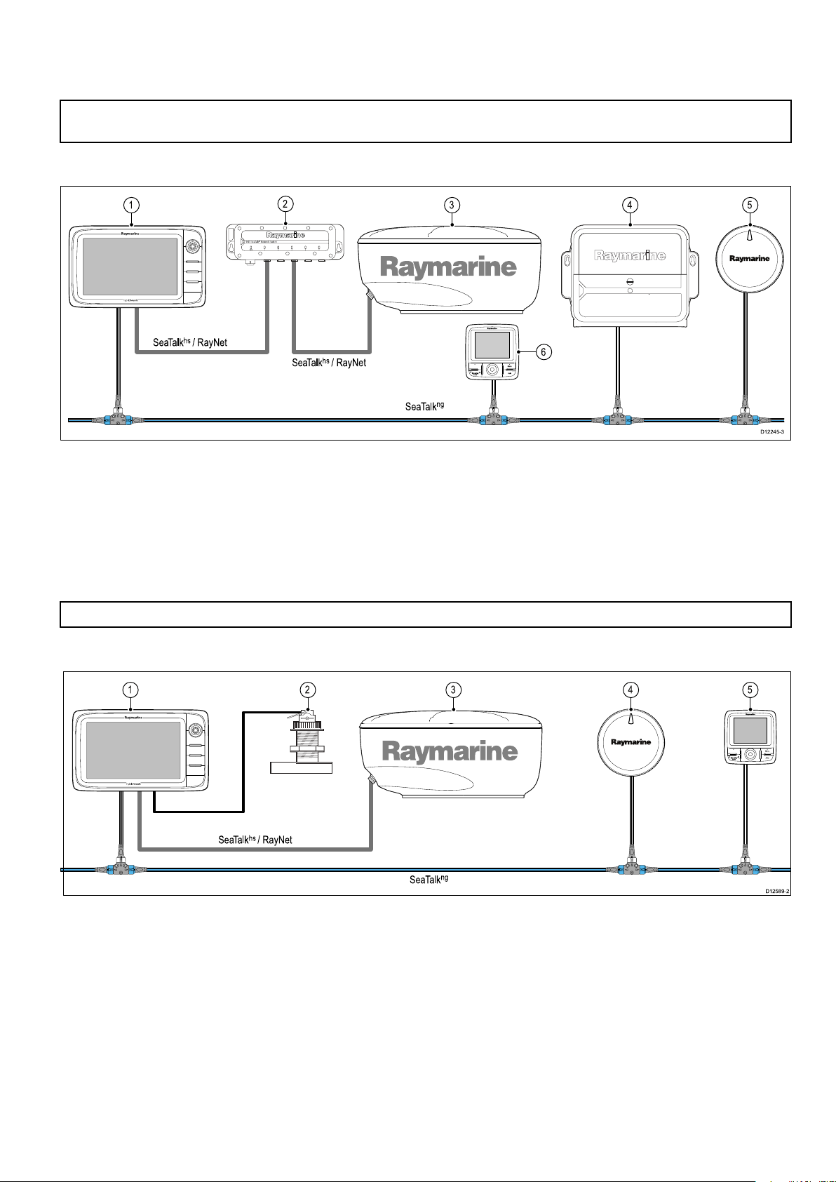
3.7Typicalsystems
SeaTalk
ng
SeaTalk
hs
/ RayNet
SeaTalk
hs
/ RayNet
6
00
D12245-3
1
2
3 4 5
SeaTalk
ng
SeaTalk
hs
/ RayNet
00
D12589-2
1 2 3 4 5
Theillustrationsbelowshowexamplesofpossiblesystemcongurations,formoredetailsoncompatible
RaymarinedevicespleaserefertotheSystemintegrationsection.
Note:Intheexamplesbelowthemultifunctiondisplay(s)couldbeanyvariantofRaymarine’s3rd
generationmultifunctiondisplayse.g.aSeries,cSeries,eSeriesorgSSeries.
Example:Basicsystem
1.Multifunctiondisplay
2.Networkswitch
3.Radarscanner
4.ActuatorControlUnit(ACU)
5.Evolutionautopilot
6.SeaT alk
ng
pilotcontroller(optional)
Note:AnetworkswitchisonlyrequiredifmultipledevicesareconnectedusingSeaT alk
Example:Basicsystemwithsonarvariantdisplay
hs
/RayNet.
1.Multifunctiondisplay
2.Sonartransducer
3.Radarscanner
4.Evolutionautopilot
ng
pilotcontroller(optional)
5.SeaT alk
Planningtheinstallation
41

Example:Basicsystemwithnon-sonarvariantdisplay
SeaTalk
ng
SeaTalk
hs
/ RayNet
00
D12590-2
1
2
3 4 5
D1224 7-2
SeaTalk
hs
/ RayNet
SeaTalk
hs
/ RayNet
SeaTalk
hs
/ RayNet
SeaTalk
hs
/ RayNet
SeaTalk
hs
/ RayNet
DeviceNet
SeaTalk
ng
SeaTalk
ng
SeaTalk
ng
SeaTalk
ng
5
1
812
11
12 12
14
9
15
2 3 4
6
13
10
7
1.Multifunctiondisplay
2.Sonarmodule
3.Sonartransducer
4.Evolutionautopilot
5.SeaT alk
ng
pilotcontroller
Example:Expandedsystem
1.Radarscanner
2.Weathersensor
3.Siriusweatherreceiver
4.Sonarmodule
5.SeaT alk
6.SeaT alk
ng
ng
Pilotcontroller
Instrumentdisplay
7.AISreceiver/transceiver
8.Audiosystem
9.Smartphone/tablet
10.DeviceNetspur(forNMEA2000devices)
11.Networkswitch
12.Multifunctiondisplays
42
aSeries/cSeries/eSeries

13.GPSreceiver
14.Thermalcamera
15.Wirelessconnection
Planningtheinstallation
43

3.8Systemprotocols
YourMultifunctionDisplaycanconnecttovarious
instrumentsanddisplaystoshareinformationand
soimprovethefunctionalityofthesystem.These
connectionsmaybemadeusinganumberof
differentprotocols.Fastandaccuratedatacollection
andtransferisachievedbyusingacombinationof
thefollowingdataprotocols:
•SeaTalk
•SeaTalk
•NMEA2000
•SeaTalk
•NMEA0183
Note:Youmayndthatyoursystemdoesnot
usealloftheconnectiontypesorinstrumentation
describedinthissection.
SeaTalk
SeaTalk
highspeedprotocolallowscompatibleequipment
tocommunicaterapidlyandsharelargeamountsof
data.
InformationsharedusingtheSeaT alk
includes:
•Sharedcartography(betweencompatible
displays).
•Digitalradardata.
•Sonardata.
Seatalk
SeaTalk
forconnectionofcompatiblemarineinstruments
andequipment.ItreplacestheolderSeaT alkand
SeaTalk
SeaTalk
compatibleinstrumentsconnectusingaspur.Data
andpowerarecarriedwithinthebackbone.Devices
thathavealowdrawcanbepoweredfromthe
network,althoughhighcurrentequipmentwillneed
tohaveaseparatepowerconnection.
SeaTalk
andtheprovenCANbustechnology .Compatible
NMEA2000andSeaT alk/SeaT alk
alsobeconnectedusingtheappropriateinterfaces
oradaptorcablesasrequired.
NMEA2000
NMEA2000offerssignicantimprovementsover
NMEA0183,mostnotablyinspeedandconnectivity.
Upto50unitscansimultaneouslytransmitand
receiveonasinglephysicalbusatanyonetime,
witheachnodebeingphysicallyaddressable.The
standardwasspecicallyintendedtoallowfor
hs
ng
hs
hs
isanethernetbasedmarinenetwork.This
ng
ng
(NextGeneration)isanenhancedprotocol
2
protocols.
ng
utilizesasinglebackbonetowhich
ng
isaproprietaryextensiontoNMEA2000
2
devicescan
hs
network
awholenetworkofmarineelectronicsfromany
manufacturertocommunicateonacommonbusvia
standardizedmessagetypesandformats.
SeaTalk
SeaTalkisaprotocolwhichenablescompatible
instrumentstoconnecttoeachotherandsharedata.
TheSeaT alkcablesystemisusedtoconnect
compatibleinstrumentsandequipment.Thecable
carriespoweranddataandenablesconnection
withouttheneedforacentralprocessor.
Additionalinstrumentsandfunctionscanbeaddedto
aSeaT alksystem,simplybypluggingthemintothe
network.SeaT alkequipmentcanalsocommunicate
withothernon-SeaT alkequipmentviatheNMEA
0183standard,providedasuitableinterfaceisused.
NMEA0183
TheNMEA0183DataInterfaceStandardwas
developedbytheNationalMarineElectronics
AssociationofAmerica.Itisaninternational
standardtoenableequipmentfrommanydifferent
manufacturerstobeconnectedtogetherandshare
information.
TheNMEA0183standardcarriessimilarinformation
toSeaT alk.Howeverithastheimportantdifference
thatonecablewillonlycarryinformationinone
direction.ForthisreasonNMEA0183isgenerally
usedtoconnectadatareceiverandatransmitter
together,e.g.acompasssensortransmitting
headingtoaradardisplay .Thisinformationis
passedin‘sentences’,eachofwhichhasathree
lettersentenceidentier.Itisthereforeimportant
whencheckingcompatibilitybetweenitemsthatthe
samesentenceidentiersareusedsomeexamples
ofwhichare:
•VTG-carriesCourseandSpeedOverGround
data.
•GLL-carrieslatitudeandlongitude.
•DBT-carrieswaterdepth.
•MWV-carriesrelativewindangleandwindspeed
data.
NMEABaudrates
TheNMEA0183standardoperatesatanumber
ofdifferentspeeds,dependingupontheparticular
requirementorequipmentcapabilities.Typical
examplesare:
•4800baudrate.Usedforgeneralpurpose
communications,includingFastHeadingdata.
•38400baudrate.UsedforAISandotherhigh
speedapplications.
44
aSeries/cSeries/eSeries

3.9Datamaster
D1258 3-2
1
4
7
5 6
8
2 3
x4
3.10a6xanda7xpartssupplied
Anysystemcontainingmorethanonenetworked
multifunctiondisplaymusthaveadesignateddata
master.
Thedatamasteristhedisplaywhichservesasa
primarysourceofdataforalldisplays,italsohandles
allexternalsourcesofinformation.Forexample
thedisplaysmayrequireheadinginformationfrom
theautopilotandGPSsystems,usuallyreceived
throughaSeaTalk
ng
orNMEAconnection.Thedata
masteristhedisplaytowhichtheSeaT alk,NMEA
andanyotherdataconnectionsaremade,itthen
bridgesthedatatotheSeaT alk
hs
networkandany
compatiblerepeatdisplays.Informationsharedby
thedatamasterincludes:
•Cartography
•Routesandwaypoints
•Radar
•Sonar
•Datareceivedfromtheautopilot,instruments,the
engineandotherexternalsources.
Yoursystemmaybewiredforredundancywithdata
connectionsmadetorepeatdisplays.Howeverthese
connectionswillonlybecomeactiveintheeventofa
faultand/orreassignmentofthedatamaster.
Thefollowingitemsaresuppliedwithyoura6xand
a7xvariantMFD.
1Frontbezel
2
Multifunctiondisplay
3Mountinggasket
4
Suncover
Inanautopilotsystemwhichdoesnotcontaina
dedicatedpilotcontrolheadtheDatamasteralso
actsasthecontrolfortheautopilot.
5
Trunnionbracketkit
6Documentationpack
7
8
Powercable
4xNuts,bolts,springwashersandwashers(can
beusedforeithersurfaceorbracketmounting.)
Planningtheinstallation
45

3.11a9xanda12xpartssupplied
D13066-1
x4
1
4
7
9
10
11
5 6
8
2 3
D12170-4
x4
x4
x4
1
2
8
3
4
5
7
9
6
3.12e7/e7DPartssupplied
Thefollowingitemsaresuppliedwithyoura9xand
a12xvariantMFD.
Thepartsshownbelowaresuppliedwiththee7/
e7Dmultifunctiondisplay.
1Frontbezel
2
3Mountinggasket
4
5
6Documentationpack
7
8
9
10
11
Multifunctiondisplay(MFD)
Suncover
Trunnionbracketkit
SeaTalk
ng
toDeviceNetadaptorcable
4xNuts,bolts,springwashersandwashers(can
beusedforeithersurfaceorbracketmounting.)
3m(9.8ft.)SeaTalk
ng
spurcable
2m(6.6ft.)RayNetcable
1.5m(4.9ft.)Poweranddatacable
(Power/NMEA/Video)
1.Suncover.
2.Frontbezel.
3.Multifunctiondisplay .
4.Rearbezel(requiredfortrunnionbracket
mounting).
5.Gasket(requiredforushmounting).
6.Screwpack,includes:
•4xrearbezelxingscrews.
•4xsetsofxings(forsurfacemounting).
•4xsetsofxings(fortrunnionbracket
mounting).
7.Documentationpack,includes:
•MultilingualCD.
•Mountingandgettingstartedmultilingualguide
•Mountingtemplate.
•Warrantypolicy
8.Poweranddatacable.
9.Trunnionbracketkit.
46aSeries/cSeries/eSeries

3.13cSeriesandeSeriesparts
D12248-2
7
1
2
3
4
6
5
D12171-2
1
4
5
3
876
2
supplied
Thepartsshownbelowaresuppliedwiththe
cSeriesandeSeries(Excludinge7ande7D)
multifunctiondisplays.
3.14Toolsrequiredforinstallation
1.Powerdrill.
2.Jigsaw.
1.Suncover
2.Frontbezel
3.Multifunctiondisplay(MFD)
4.Gasket(requiredforsurfacemounting)
5.4xsetsofxings(forsurfacemounting)
6.Documentationpack,includes:
•MultilingualCD
•Mountingandgettingstartedmultilingualguide
•Mountingtemplate
•Warrantypolicy
7.Poweranddatacable
3.Pozidrivescrewdriver.
4.Adhesivetape.
5.Spannerforsurfacemountingorbracket
mountingxings.
6.File.
7.Holesawforushmounting(Forholesawsize
refertoyourproduct’smountingtemplate).
8.Drillbitforsurfacemountingorbracketmounting.
Planningtheinstallation
47
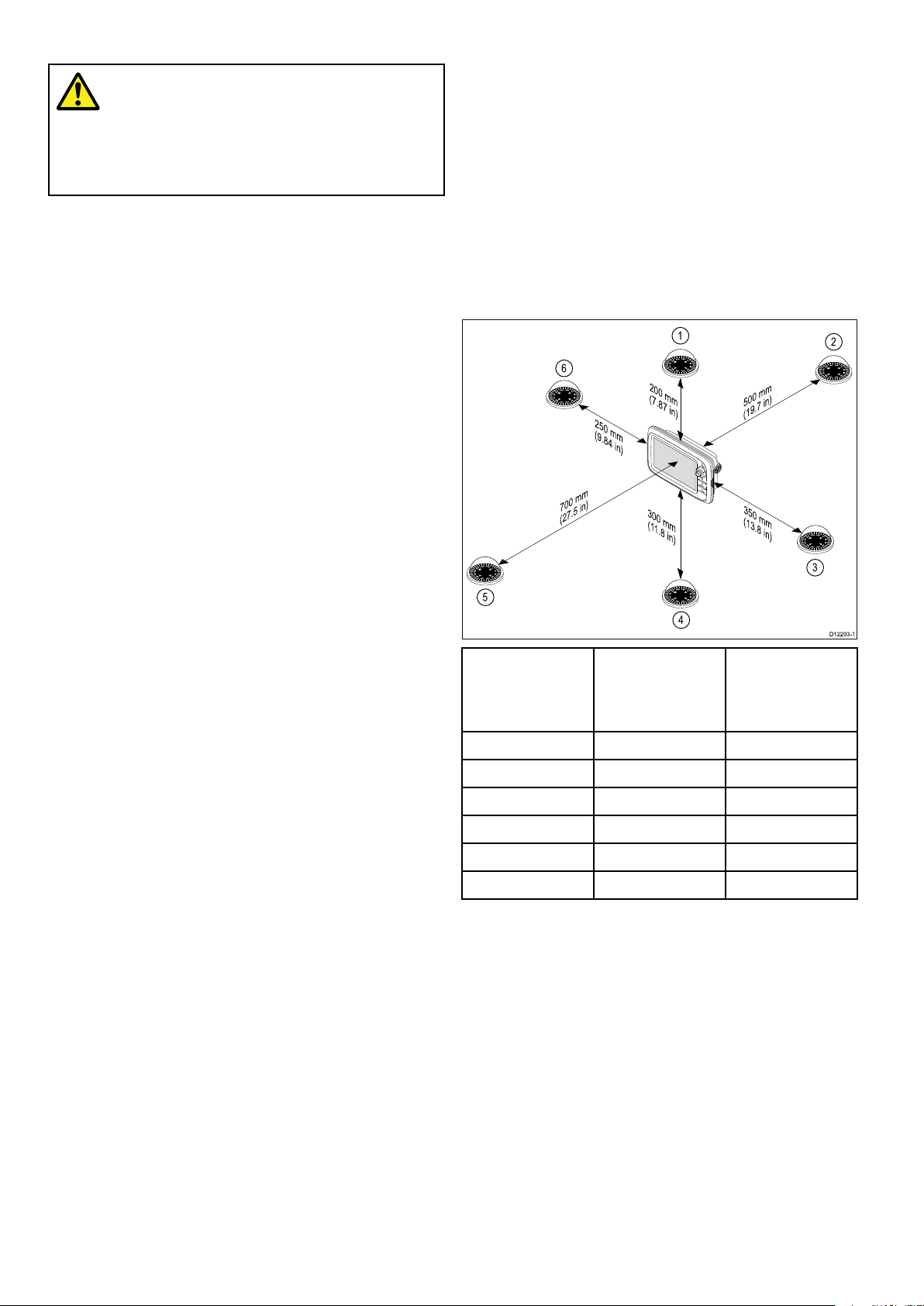
3.15Selectingalocation
D1220 3-1
200 mm
(7.87 in)
350 mm
(13.8 in)
300 mm
(11.8 in
)
700 mm
(27.5 in)
500 mm
(19.7 in)
250 mm
(9.84 in)
1
2
3
4
5
6
Compasssafedistance
Warning:Potentialignitionsource
ThisproductisNOTapprovedforusein
hazardous/ammableatmospheres.Do
NOTinstallinahazardous/ammable
atmosphere(suchasinanengineroom
ornearfueltanks).
Generallocationrequirements
Whenselectingalocationforyourproductitis
importanttoconsideranumberoffactors.
Keyfactorswhichcanaffectproductperformance
are:
•Ventilation
Toensureadequateairow:
–Ensurethatproductismountedina
compartmentofsuitablesize.
–Ensurethatventilationholesarenotobstructed.
Allowadequateseparationofallequipment.
Anyspecicrequirementsforeachsystem
componentareprovidedlaterinthischapter.
Topreventpotentialinterferencewiththevessel's
magneticcompasses,ensureanadequatedistance
ismaintainedfromthedisplay .
Whenchoosingasuitablelocationforthe
multifunctiondisplayyoushouldaimtomaintainthe
maximumpossibledistancebetweenthedisplayand
anycompasses.Typicallythisdistanceshouldbeat
least1m(3ft)inalldirections.Howeverforsome
smallervesselsitmaynotbepossibletolocate
thedisplaythisfarawayfromacompass.Inthis
situation,thefollowingguresprovidetheminimum
safedistancethatshouldbemaintainedbetweenthe
displayandanycompasses.
•Mountingsurface
Ensureproductisadequatelysupportedona
securesurface.Donotmountunitsorcutholes
inplaceswhichmaydamagethestructureofthe
vessel.
•Cabling
Ensuretheproductismountedinalocationwhich
allowsproperrouting,supportandconnectionof
cables:
–Minimumbendradiusof100mm(3.94in)
unlessotherwisestated.
–Usecableclipstopreventstressonconnectors.
–Ifyourinstallationrequiresmultipleferritesto
beaddedtoacablethenadditionalcableclips
shouldbeusedtoensuretheextraweightof
thecableissupported.
•Wateringress
Theproductissuitableformountingbothabove
andbelowdecks.Althoughtheunitiswaterproof,
itisgoodpracticetolocateitinaprotectedarea
awayfromprolongedanddirectexposuretorain
andsaltspray.
•Electricalinterference
Selectalocationthatisfarenoughawayfrom
devicesthatmaycauseinterference,suchas
motors,generatorsandradiotransmitters/
receivers.
•Powersupply
Selectalocationthatisascloseaspossibletothe
vessel’sDCpowersource.Thiswillhelptokeep
cablerunstoaminimum.
Compass
positionin
relationto
Item
display
1Top
2Rear
3Right-handside
4Underside
5
6
Front
Left-handside250mm(9.84in.)
Minimumsafe
distancefrom
display
200mm(7.87in.)
500mm(19.7in.)
350mm(13.8in.)
300mm(11.8in.)
700mm(27.5in.)
GPSlocationrequirements
Inadditiontogeneralguidelinesconcerningthe
locationofmarineelectronics,thereareanumber
ofenvironmentalfactorstoconsiderwheninstalling
equipmentwithaninternalGPSantenna.
Mountinglocation
•AboveDecksmounting:
ProvidesoptimalGPSperformance.(For
equipmentwithappropriatewaterproofrating.)
•BelowDecksmounting:
GPSperformancemaybelesseffectiveandmay
requireanexternalGPSantennamountedabove
decks.
48aSeries/cSeries/eSeries

D11537 -2
1
2
3
1
2
3
aSeriesproductdimensions
D12579-2
A
DC
F
B
E
D12269-3
A
D C
F
B
E
1.
ThislocationprovidesoptimalGPS
performance(abovedecks).
2.
Inthislocation,GPSperformancemaybeless
effective.
3.
ThislocationisNOTrecommendedforGPS
antenna.
Vesselconstruction
Theconstructionofyourvesselcanhaveanimpact
onGPSperformance.Forexample,theproximity
ofheavystructuresuchasastructuralbulkhead,
ortheinterioroflargervesselsmayresultina
reducedGPSsignal.Beforelocatingequipment
withaninternalGPSantennabelowdecks,seek
professionalassistanceandconsideruseofan
externalGPSantennamountedabovedecks.
Prevailingconditions
a6x
A163.6mm
(6.4in.)
B143.5mm
(5.6in.)
17.5mm
C
(0.7in.)
D56.6mm
(2.2in.)
E162.4mm
(6.4in.)
F150mm
(5.9in.)
a7x
205.1mm
(8in.)
147.1mm
(5.8in.)
14.5mm
(0.57in.)
59.1mm
(2.3in.)
163.3mm
(6.4in.)
150mm
(5.9in.)
cSeriesandeSeriesproductdimensions
a9xa12x
250.1mm
(9.8in.)
189.5mm
(7.5in.)
14.5mm
(0.57in.)
68.1mm
(2.7in.)
198.26mm
(7.8in.)
150mm
(5.9in.)
318mm
(12.5in.)
238.3mm
(9.4in.)
14.5mm
(0.57in.)
69.6mm
(2.7in.)
248.14mm
(9.8in.)
150mm
(5.9in.)
Theweatherandlocationofthevesselcanaffectthe
GPSperformance.Typicallycalmclearconditions
provideforamoreaccurateGPSx.Vesselsat
extremenortherlyorsoutherlylatitudesmayalso
receiveaweakerGPSsignal.GPSantennamounted
belowdeckswillbemoresusceptibletoperformance
issuesrelatedtotheprevailingconditions.
Viewingangleconsiderations
Asdisplaycontrast,colorandnightmode
performanceareallaffectedbytheviewingangle,
Raymarinerecommendsyoutemporarilypowerup
thedisplaywhenplanningtheinstallation,toenable
youtobestjudgewhichlocationgivestheoptimum
viewingangle.
Planningtheinstallation
A233mm
B144mm
C
D63.5mm
E177mm
F160mm
e7/e7D
(9.17in.)
(5.67in.)
30mm
1.18in.)
(2.5in.)
(6.97in.)
(6.29in.)
e95/e97/
c95/c97
289.6mm
(11.4in.)
173.1mm
(6.81in.)
31.4mm
(1.24in.)
63.9mm
(2.5in.)
212mm
(8.35in.)
160mm
(6.29in.)
e125/
e127/
c125/
c127
353.6mm
(13.92in.)
222mm
(8.74in.)
31.9mm
(1.26in.)
68.9mm
(2.71in.)
256.5mm
(10.1in.)
160mm
(6.29in.)
e165
426mm
(16.8in.)
281.4mm
(11.1in.)
31.4mm
(1.24in.)
69.8mm
(2.75in.)
292mm
(11.5in.)
160mm
(6.29in.)
49

50aSeries/cSeries/eSeries

Chapter4:Cablesandconnections
Chaptercontents
•4.1Generalcablingguidanceonpage52
•4.2Connectionsoverviewonpage53
•4.3a9xanda12xconnectionsoverviewonpage54
•4.4Powerconnection—a6xanda7xonpage54
•4.5Poweranddataconnectiononpage56
•4.6Networkconnectionsonpage59
•4.7Keypadconnectiononpage59
•4.8Radarconnectiononpage60
•4.9Sonarconnectiononpage62
•4.10Thermalcameraconnectiononpage65
•4.11IPCameraconnectionsonpage66
•4.12Weatherreceiverconnectiononpage67
•4.13Fusionlinkconnectiononpage67
•4.14GPSconnectiononpage68
•4.15GA150connectiononpage69
•4.16AISconnectiononpage70
•4.17Fastheadingconnectiononpage70
•4.18SeaTalk
•4.19NMEA2000connectiononpage72
•4.20SeaTalkconnectiononpage72
•4.21NMEA0183connectiononpage73
•4.22a6xanda7xtoNMEA0183DSCVHFradioconnectiononpage74
•4.23Camera/Videoconnectiononpage74
•4.24Camera/videoin-outconnectiononpage75
•4.25Mediaplayerconnectiononpage76
•4.26Bluetoothremotecontrolconnectiononpage77
•4.27Remotecontrolfunctionsonpage79
•4.28WiFiconnectionsonpage81
ng
connectionsonpage71
Cablesandconnections51

4.1Generalcablingguidance
100 mm (4 in)
200 mm (8 in)
Cabletypesandlength
Itisimportanttousecablesoftheappropriatetype
andlength
•Unlessotherwisestateduseonlystandardcables
ofthecorrecttype,suppliedbyRaymarine.
•Ensurethatanynon-Raymarinecablesareofthe
correctqualityandgauge.Forexample,longer
powercablerunsmayrequirelargerwiregauges
tominimizevoltagedropalongtherun.
Routingcables
Cablesmustberoutedcorrectly,tomaximize
performanceandprolongcablelife.
•DoNOTbendcablesexcessively.Wherever
possible,ensureaminimumbenddiameterof200
mm(8in)/minimumbendradiusof100mm(4in).
•AlwaysuseanRS232/NMEAconverterwith
opticalisolationonthesignallines.
•AlwaysmakesurethatPC’sorothersensitive
electronicdeviceshaveadedicatedpowercircuit.
Cableshielding
Ensurethatalldatacablesareproperlyshielded
thatthecableshieldingisintact(e.g.hasn’tbeen
scrapedoffbybeingsqueezedthroughatightarea).
•Protectallcablesfromphysicaldamageand
exposuretoheat.Usetrunkingorconduitwhere
possible.DoNOTruncablesthroughbilgesor
doorways,orclosetomovingorhotobjects.
•Securecablesinplaceusingtie-wrapsorlacing
twine.Coilanyextracableandtieitoutoftheway.
•Whereacablepassesthroughanexposed
bulkheadordeckhead,useasuitablewatertight
feed-through.
•DoNOTruncablesneartoenginesoruorescent
lights.
Alwaysroutedatacablesasfarawayaspossible
from:
•otherequipmentandcables,
•highcurrentcarryingacanddcpowerlines,
•antennae.
Strainrelief
Ensureadequatestrainreliefisprovided.Protect
connectorsfromstrainandensuretheywillnotpull
outunderextremeseaconditions.
Circuitisolation
Appropriatecircuitisolationisrequiredfor
installationsusingbothACandDCcurrent:
•Alwaysuseisolatingtransformersoraseparate
power-invertertorunPC’s,processors,displays
andothersensitiveelectronicinstrumentsor
devices.
•AlwaysuseanisolatingtransformerwithWeather
FAXaudiocables.
•Alwaysuseanisolatedpowersupplywhenusing
a3rdpartyaudioamplier.
52aSeries/cSeries/eSeries

4.2Connectionsoverview
D12249-7
e7
e7D
e95 / e125 / e165
e97 / e127
c95 / c125
c97 / c127
a65 / a75
a67 / a68 / a7 7 / a78
0
0
000
0
0
000
DetailsoftheconnectionsavailableonRaymarinemultifunctiondisplaysareshownbelow.
a65
a65Wi-Fi
a67
a67Wi-Fi
a68
a68Wi-Fi
a75
a75Wi-Fi
a77
a77Wi-Fi
a78
a78Wi-Fi
e7
DownViTransducer
siontrans-
ducerSeaTalk
ng
SeaTalk
/RayNet
Network1
hs
SeaTalk
/RayNet
Network2
hs
Videoin/
outPower
Power/Data
Video/
NMEA
0183
e7D
e95
e97
e125
e127
e165
c95
c97
c125
c127
Cablesandconnections53

4.3a9xanda12xconnectionsoverview
D13068-1
1 2 3 4 5 6
0
0
000
1
6
2
4
5
3
D12581-2
Thea9xanda12xvariantMFDsincludethefollowing
connections.
4.4Powerconnection—a6xanda7x
1.Sonartransducer(a97anda127)/DownVision
transducer(a98anda128)
2.SeaT alk
3.Network1(RayNet)
4.Network2(RayNet)
5.Poweranddata
6.GA150antenna
ng
TM
1.Multifunctiondisplayrearpanelconnections.
2.Powercable.
3.Connectionto12Vpowersupply
4.Redcable(positive).
5.Shield(drain)wire(thinblackwire;mustbe
connectedtoRFgroundpoint).
6.Blackcable(negative).
Powerdistribution
Raymarinerecommendsthatallpowerconnections
aremadeviaadistributionpanel.
•Allequipmentmustbepoweredfromabreakeror
switch,withappropriatecircuitprotection.
•Allequipmentshouldbewiredtoindividual
breakersifpossible.
Warning:Productgrounding
Beforeapplyingpowertothisproduct,
ensureithasbeencorrectlygrounded,in
accordancewiththeinstructionsinthis
guide.
Grounding—Dedicateddrainwire
Thepowercablesuppliedwiththisproductincludes
adedicatedshield(drain)wireforconnectiontoa
vessel'sRFgroundpoint.
ItisimportantthataneffectiveRFgroundis
connectedtothesystem.Asinglegroundpoint
shouldbeusedforallequipment.Theunitcanbe
groundedbyconnectingtheshield(drain)wireof
thepowercabletothevessel'sRFgroundpoint.
OnvesselswithoutanRFgroundsystemtheshield
(drain)wireshouldbeconnecteddirectlytothe
negativebatteryterminal.
54aSeries/cSeries/eSeries
Thedcpowersystemshouldbeeither:
•Negativegrounded,withthenegativebattery
terminalconnectedtothevessel'sground.
•Floating,withneitherbatteryterminalconnected
tothevessel'sground
Warning:Positivegroundsystems
Donotconnectthisunittoasystemwhich
haspositivegrounding.
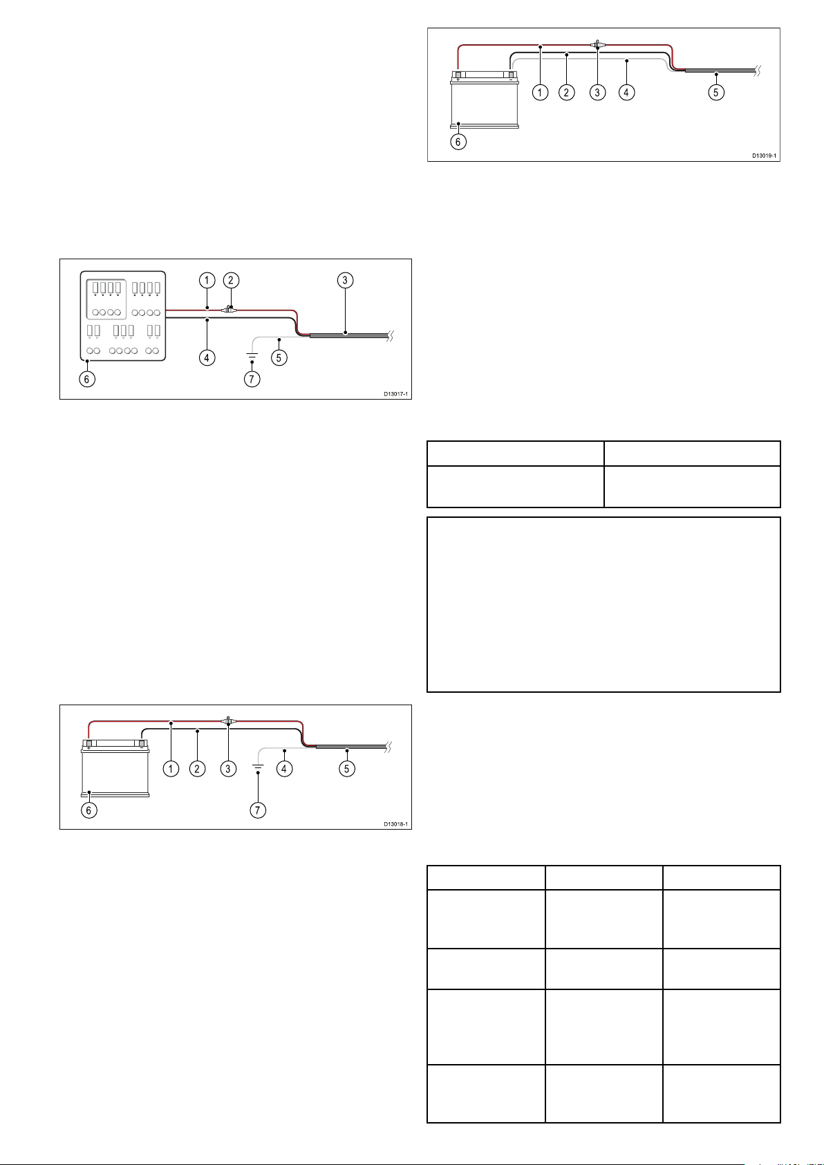
Breakers,fusesandcircuitprotection
D13017-1
2 31
4 5
6 7
D13018-1
2 4 51 3
6 7
D13019-1
2 4 51 3
6
Theinformationbelowisprovidedasguidance
tohelpprotectyourproduct.Theexample
illustrationsprovidedareforcommonvesselpower
arrangements,ifyouareunsurehowtoprovidethe
correctlevelofprotectionthenpleaseconsulta
Raymarineauthorizeddealerforsupport.
Distributionpanelconnection
Itisrecommendedthatyourproductiswiredthrough
yourvessel’sdistributionpanelviaathermalbreaker
orfuse.
1.Vesselpowersupplypositive(+)
2.In-linefuse.(Ifyourproductspowercabledoes
nothaveanin-linefusethenanonefuseshould
betted.)
3.Productpowercable
4.Vesselpowersupplynegative(-)
5.*Drainwire
6.Vesseldistributionpanel
7.VesselRFgroundpointconnection
BatteryconnectionwithRFground
Ifyourvesseldoesnothaveadistributionpanelthen
yourproductmaybewireddirectlytothebatterywith
thedrainwireconnectedtothevessel’sRFground
point.
1.Vesselpowersupplypositive(+)
2.Vesselpowersupplynegative(-)
3.In-linefuse(Ifyourproductspowercabledoes
nothaveabuiltinfusethenanin-linefuse
shouldbetted.)
4.Drainwireconnectedtovesselnegativepower
supply.
5.Productpowercable
6.Vesselbattery
In-linefuseandthermalbreakerratings
Thefollowingin-linefuseandthermalbreakerratings
applytoyourproduct:
In-linefuseratingThermalbreakerrating
5A
3A(ifonlyconnectingone
device)
Note:
•Thesuitablefuseratingforthethermalbreaker
isdependentonthenumberofdevicesyouare
connecting.Ifindoubtconsultanauthorized
Raymarinedealer.
•Yourproduct’spowercablemayhavetted
in-linefuse,ifnotthenyoucanaddanin-line
fusetothepositivewireofyourproductspower
connection.
Powercable
DependingonMultifunctiondisplayvariant,the
displayiseithersuppliedwithapowercableora
combinedpoweranddatacable.
Powercablesavailable
1.Vesselpowersupplypositive(+)
2.Vesselpowersupplynegative(-)
3.In-linefuse(Ifyourproductspowercabledoes
nothaveabuiltinfusethenanin-linefuse
shouldbetted.)
4.*Drainwire
5.Productpowercable
6.Vesselbattery
7.VesselRFgroundpointconnection
BatteryconnectionwithnoRFground
Ifyourvesseldoesnothaveadistributionpanel
oranRFgroundpointthenyourproductmaybe
wireddirectlytothebatterywiththedrainwirealso
connectedtothebattery’snegativeterminal.
Cablesandconnections55
Forushmountinstallationsarightangledpower
cableisavailable.
CablePartnumberMFDvariant
Straightpower
R70157a6xanda7x
cable(supplied
witha6xanda7x)
Rightangled
A80221a6xanda7x
powercable
Straightpower
R62379Allvariants
anddatacable
(suppliedwitha9x
anda12x)
Rightangled
R70029Allvariants
poweranddata
cable
excludinga6xand
a7x
excludinga6xand
a7x

Cableextension
D11637 -2
2
4 4
1
3
+
-
D12250-2
2
1
4
5
7
3
8
6
9
4.5Poweranddataconnection
Powercablescanbeextendedifrequired.The
followingrestrictionsapplytoanyextensiontothe
powercable:
•Cablemustbeofasuitablegaugeforthecircuit
load.
•Eachunitshouldhaveitsowndedicatedpower
cablewiredbacktothedistributionpanel.
Totallength
(max)Supplyvoltage
0–5m(0–16.4ft)
12V18
Cablegauge
(AWG)
24V20
12V14 5–10m
(16.4–32.8ft)
24V18
12V12 10–15m
(32.8–49.2ft)
24V16
12V12 15–20m
(49.2–65.5ft)
24V14
Note:a6xanda7xMFDsare12Vonlyproducts.NEVER
connecta12Vonlyproducttoa24Vsystem.
Sharingabreaker
Wheremorethan1pieceofequipmentsharesa
breakeryoumustprovideprotectionfortheindividual
circuits.E.g.byconnectinganin-linefuseforeach
powercircuit.
ThedetailsbelowapplytoMFDswhichhavea
combinedpoweranddatacable.
1.Poweranddataconnection
2.Poweranddatacable
3.Connectiontovessel’s12V/24Vdcpower
supply
4.Redcable(positive)
5.Fuse
6.Blackcable(negative)
7.Videoinputcable
8.NMEA0183datacables
9.Shield(drain)wire(thinblackwire;mustbe
connectedtoRFgroundpoint)
Powerdistribution
Raymarinerecommendsthatallpowerconnections
aremadeviaadistributionpanel.
•Allequipmentmustbepoweredfromabreakeror
switch,withappropriatecircuitprotection.
•Allequipmentshouldbewiredtoindividual
breakersifpossible.
Warning:Productgrounding
Beforeapplyingpowertothisproduct,
ensureithasbeencorrectlygrounded,in
accordancewiththeinstructionsinthis
guide.
1
2
3
4Fuse
Wherepossible,connectindividualitemsof
equipmenttoindividualcircuitbreakers.Wherethis
isnotpossible,useindividualin-linefusestoprovide
thenecessaryprotection.
56aSeries/cSeries/eSeries
Positive(+)bar
Negative(-)bar
Circuitbreaker
Grounding—Dedicateddrainwire
Thepowercablesuppliedwiththisproductincludes
adedicatedshield(drain)wireforconnectiontoa
vessel'sRFgroundpoint.
ItisimportantthataneffectiveRFgroundis
connectedtothesystem.Asinglegroundpoint
shouldbeusedforallequipment.Theunitcanbe
groundedbyconnectingtheshield(drain)wireof
thepowercabletothevessel'sRFgroundpoint.
OnvesselswithoutanRFgroundsystemtheshield
(drain)wireshouldbeconnecteddirectlytothe
negativebatteryterminal.
Thedcpowersystemshouldbeeither:

•Negativegrounded,withthenegativebattery
D13017-1
2 31
4 5
6 7
D13018-1
2 4 51 3
6 7
D13019-1
2 4 51 3
6
terminalconnectedtothevessel'sground.
•Floating,withneitherbatteryterminalconnected
tothevessel'sground
Warning:Positivegroundsystems
Donotconnectthisunittoasystemwhich
haspositivegrounding.
Breakers,fusesandcircuitprotection
Theinformationbelowisprovidedasguidance
tohelpprotectyourproduct.Theexample
illustrationsprovidedareforcommonvesselpower
arrangements,ifyouareunsurehowtoprovidethe
correctlevelofprotectionthenpleaseconsulta
Raymarineauthorizeddealerforsupport.
6.Vesselbattery
7.VesselRFgroundpointconnection
BatteryconnectionwithnoRFground
Ifyourvesseldoesnothaveadistributionpanel
oranRFgroundpointthenyourproductmaybe
wireddirectlytothebatterywiththedrainwirealso
connectedtothebattery’snegativeterminal.
1.Vesselpowersupplypositive(+)
Distributionpanelconnection
Itisrecommendedthatyourproductiswiredthrough
yourvessel’sdistributionpanelviaathermalbreaker
orfuse.
1.Vesselpowersupplypositive(+)
2.In-linefuse.(Ifyourproductspowercabledoes
nothaveanin-linefusethenanonefuseshould
betted.)
3.Productpowercable
4.Vesselpowersupplynegative(-)
5.*Drainwire
6.Vesseldistributionpanel
7.VesselRFgroundpointconnection
2.Vesselpowersupplynegative(-)
3.In-linefuse(Ifyourproductspowercabledoes
nothaveabuiltinfusethenanin-linefuse
shouldbetted.)
4.Drainwireconnectedtovesselnegativepower
supply.
5.Productpowercable
6.Vesselbattery
In-linefuseandthermalbreakerratings
Thefollowingin-linefuseandthermalbreakerratings
applytoyourproduct:
In-linefuseratingThermalbreakerrating
7A
5A(ifonlyconnectingone
device)
Note:
•Thesuitablefuseratingforthethermalbreaker
isdependentonthenumberofdevicesyouare
connecting.Ifindoubtconsultanauthorized
Raymarinedealer.
BatteryconnectionwithRFground
Ifyourvesseldoesnothaveadistributionpanelthen
yourproductmaybewireddirectlytothebatterywith
thedrainwireconnectedtothevessel’sRFground
•Yourproduct’spowercablemayhavetted
in-linefuse,ifnotthenyoucanaddanin-line
fusetothepositivewireofyourproductspower
connection.
point.
Powercable
DependingonMultifunctiondisplayvariant,the
displayiseithersuppliedwithapowercableora
combinedpoweranddatacable.
Powercablesavailable
Forushmountinstallationsarightangledpower
1.Vesselpowersupplypositive(+)
2.Vesselpowersupplynegative(-)
3.In-linefuse(Ifyourproductspowercabledoes
nothaveabuiltinfusethenanin-linefuse
shouldbetted.)
4.*Drainwire
5.Productpowercable
Cablesandconnections57
cableisavailable.
CablePartnumberMFDvariant
Straightpower
R70157a6xanda7x
cable(supplied
witha6xanda7x)
Rightangled
A80221a6xanda7x
powercable

CablePartnumberMFDvariant
D11637 -2
2
4 4
1
3
+
-
3
Circuitbreaker
Straightpower
anddatacable
(suppliedwitha9x
R62379Allvariants
excludinga6xand
a7x
anda12x)
Rightangled
poweranddata
cable
R70029Allvariants
excludinga6xand
a7x
Cableextension
Powercablescanbeextendedifrequired.The
followingrestrictionsapplytoanyextensiontothe
powercable:
•Cablemustbeofasuitablegaugeforthecircuit
load.
•Eachunitshouldhaveitsowndedicatedpower
cablewiredbacktothedistributionpanel.
Totallength
(max)Supplyvoltage
0–5m(0–16.4ft)
12V18
Cablegauge
(AWG)
24V20
4Fuse
Wherepossible,connectindividualitemsof
equipmenttoindividualcircuitbreakers.Wherethis
isnotpossible,useindividualin-linefusestoprovide
thenecessaryprotection.
12V14 5–10m
(16.4–32.8ft)
24V18
12V12 10–15m
(32.8–49.2ft)
24V16
12V12 15–20m
(49.2–65.5ft)
24V14
Note:a6xanda7xMFDsare12Vonlyproducts.NEVER
connecta12Vonlyproducttoa24Vsystem.
Sharingabreaker
Wheremorethan1pieceofequipmentsharesa
breakeryoumustprovideprotectionfortheindividual
circuits.E.g.byconnectinganin-linefuseforeach
powercircuit.
1
2
58aSeries/cSeries/eSeries
Positive(+)bar
Negative(-)bar
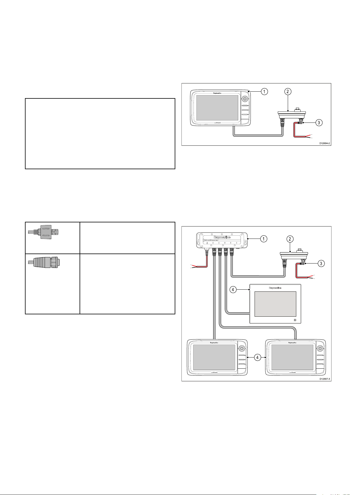
4.6Networkconnections
D12694-2
2
3
1
D12697-3
4
1
2
3
4
4.7Keypadconnection
Youcanconnectcompatibledevicestoyour
multifunctiondisplayusingtheNetworkconnector(s)
attherearoftheunit.
Atypicalnetworkofdigitaldevicesmayinclude:
•Upto6Raymarinemultifunctiondisplays.
•RayNetorSeaT alk
hs
digitaldevicessuchasa
sonarmoduleandradarscanner.
•ThermalorIPcameras.
Note:Y ourmultifunctiondisplayincludesthe
followingnetworkconnectors:
•e7,e7DandaSeries=1xRayNetnetwork
connector.
•cSeriesandeSeries(excludingthee7and
e7D)=2xRayNetnetworkconnectors.
Networksrequiringadditionalnetworkconnections
willrequireaRaymarinenetworkswitch.
PleaserefertoChapter33Sparesandaccessories
fordetailsofavailablenetworkcablesandhardware.
Networkcableconnectortypes
Thereare2typesofnetworkcableconnector—
SeaTalk
hs
andRayNet.
SeaTalk
connectingSeaTalk
hs
connector—usedfor
hs
devicesto
aRaymarinenetworkswitchvia
SeaTalk
hs
cables.
AremotekeypadsuchastheRMK-9canbe
connecteddirectlytothemultifunctiondisplay’s
networkconnectororviaanetworkswitch.Multiple
keypadscanbeconnectedtoasystem.Each
keypadcanbeusedtocontrolupto4multifunction
displays.
Directconnection
1.Multifunctiondisplay .
2.Keypad.
3.Rightangledpowercable.
WhenconnectingthekeypaddirectlytoaNewa
Series,NewcSeriesorNeweSeriesmultifunction
displaythekeypadmustbepoweredseparately,
usingthealternatepowerconnector.
Networkconnection
RayNetconnector—usedfor
connectingRaymarinenetwork
switchesandSeaTalk
hs
devicesto
themultifunctiondisplayviaRayNet
cables.Alsorequiredforconnectinga
crossovercouplerifonlyonedevice
isbeingconnectedtothedisplay's
Networkconnector.
1.Networkswitch.
2.Keypad.
3.Rightangledpowercable.
4.Networkedmultifunctiondisplays.
Whenconnectingthekeypadviaanetworkswitch
thekeypadmustbepoweredseparately,usingthe
alternatepowerconnector.
Onceconnectedthekeypadmustbepairedwiththe
eachmultifunctiondisplayyouwanttocontrolusing
Cablesandconnections59
thekeypad.

4.8Radarconnection
Dxxxxx-x
3
4
2
1
5
6
D12253-2
2
4
3
1
1
2
3
D12884-1
Themultifunctiondisplayiscompatiblewith
RaymarineNon-HDdigitalradomesandHD/
SuperHDradarscanners.Thescannerisconnected
usingoverSeaT alk
Note:
•NewcSeriesandNeweSeriesdisplays
(excludingthee7ande7D)canconnect2
SeaTalk
hs
display.
hs
.
/RayNetdevicesdirectlytothe
Radarconnecteddirectlytothedisplay
•NewaSeriesandthee7/e7Ddisplayscan
connect1SeaT alk
hs
/RayNetdevicedirectlyto
thedisplay.
TheradarisusuallyconnectedviaaRaymarine
networkswitch.Onsmallersystems(withonlyone
displayandnootherdigitaldevices)theradarmay
beconnectedtothedisplaydirectly.
RadarconnectedusingRaymarinenetwork
switch
1.Radarscanner
2.Multifunctiondisplayrearconnectorpanel.
3.RayNetRadarcable.
4.Connectiontopowersupply—Openarray
scannersrequireaVCM(VoltageConverter
Module).
RJ45SeaTalk
hs
Radarcableconnection
ToconnectaRadarusinganRJ45SeaTalk
cableadditionalaccessoriesarerequired.
hs
radar
1.Radarscanner.
2.Raymarinenetworkswitch.
3.RayNetcable.
4.RayNetradarcable.
5.VCM(VoltageConverterModule)—required
forOpenArrays.
6.Powerconnection.
Radarcableextension
Forlongercablerunsaradarpoweranddatadigitalcableextensionisrequired.
60aSeries/cSeries/eSeries
1.RJ45SeaTalk
2.RayNettoRJ45SeaTalk
3.SeaT alk
hs
Radarcable.
hs
crossovercoupler.
hs
adaptorcable.

D1225 4-1
1 42
3
1.Radarextensioncable.
2.Radarpoweranddatadigitalcable.
3.Raymarinenetworkswitch(orcrossovercouplerifconnectingradardirectlytodisplay).
4.RayNetcable(orRayNettoSeaT alk
hs
cableifconnectingviacrossovercoupler).
Note:Theextensioncableconnectstotheradarscanner.
Note:ThepowerconnectionisNOTshowninthediagram.IfusinganOpenArrayscanneraVCM
(VoltageConverterModule)mustbeconnectedbetweenthescannerandthepowersupply .
Digitalradarcables
Youwillneedadedicatedradarpoweranddata
digitalcableandappropriatenetworkcablesto
connectyourscannertoyoursystem.
ConnectionRequiredcable
Radarscannertopower
supplyandRaymarine
networkswitch.
Poweranddatadigital
cable.Forlongercableruns,
extensionsareavailableina
varietyoflengths.
Raymarinenetworkswitchto
multifunctiondisplay.
SeaTalk
hs
Radarpoweranddatadigital
Networkcables,availablein
avarietyofcablelengths.
cables
Thesecablescontainthewiresforascanner'spower
anddataconnections.
CablePartnumber
RJ45SeaTalk
hs
5m(16.4ft)
Poweranddatadigitalcable
RJ45SeaTalk
hs
10m(32.8ft)
Poweranddatadigitalcable
RJ45SeaTalk
hs
15m(49.2ft)
Poweranddatadigitalcable
RJ45SeaTalk
hs
25m(82.0ft)
Poweranddatadigitalcable
Note:Themaximumlengthfortheradarpower
anddatadigitalcable(includinganyextensions)
is25m(82ft).
A55076D
A55077D
A55078D
A55079D
RayNetRadarpoweranddatadigitalcables
Thesecablescontainthewiresforascanner'spower
anddataconnections.
CablePartnumber
RayNet5m(16.4ft)Power
A80227
anddatadigitalcable
RayNet10m(32.8ft)Power
A80228
anddatadigitalcable
RayNet15m(49.2ft)Power
A80229
anddatadigitalcable
RayNet25m(82.0ft)Power
A80230
anddatadigitalcable
Note:Themaximumlengthfortheradarpower
anddatadigitalcable(includinganyextensions)
is25m(82ft).
Radarpoweranddatadigitalextension
cables
Thesecablesextendthepoweranddatadigital
cablesforascanner'spoweranddataconnections.
CablePartnumber
2.5m(8.2ft)Poweranddata
digitalcable
5m(16.4ft)Poweranddata
digitalcable
10m(32.8ft)Poweranddata
digitalcable
A92141D
A55080D
A55081D
Cablesandconnections61
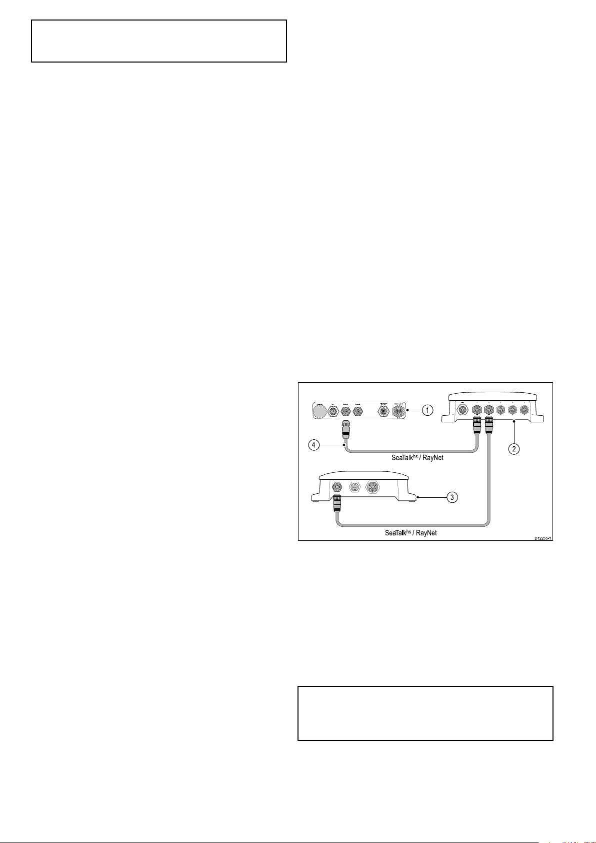
Note:Themaximumlengthfortheradarpower
SeaTalk
hs
/ RayNet
SeaTalk
hs
/ RayNet
D1225 5-1
1
2
3
4
anddatadigitalcable(includinganyextensions)
is25m(82ft).
4.9Sonarconnection
Asonarconnectionisrequiredtoenableuseofthe
Fishnderapplication.
TheMFDcanbeusedwiththefollowingRaymarine
sonarmodules:
•CP450C
•CP300
•CP200
•CP100
Thereare2typesofconnectionrequiredfor
Fishnderapplications:
•Sonarmoduleconnection—convertsthesonar
signalsprovidedbythesonartransducerinto
datasuitableforamarineelectronicssystem.
Thesonarvariantmultifunctiondisplaysfeature
abuilt-insonar,enablingyoutoconnectthe
displaydirectlytoacompatiblesonartransducer.
Non-sonarvariantsrequireaconnectiontoan
externalRaymarinesonarmodule.Internal
andexternalsonarsrequireaconnectiontoa
compatiblesonartransducer.
•Sonartransducerconnection—providessonar
signalstothesonarmodule.
Sonarmoduleconnection
1.Rearconnectorpanelofmultifunctiondisplay
(Non-sonarvariant).
2.Raymarinenetworkswitch.
3.Raymarinesonarmodule.
4.RayNetcable.
Ifasparenetworkconnectionisavailableonyour
multifunctiondisplaythenasonarmodulemaybe
connecteddirectlytothedisplay,withoutusinga
Raymarinenetworkswitch.
Note:Y oucanalsoconnectasonarvariantMFD
toaRaymarine
®
sonarmodule.Thisisusefulin
circumstanceswhereyouneedahigherpowered
sonarmoduleforexample.
Multipleactivesonarmodules
Multipleactivesonarmodulescanbepresentonthe
samenetwork,youmustselectwhichsonarmodule/
62aSeries/cSeries/eSeries
channelyouwanttouseintheFishnderapplication.
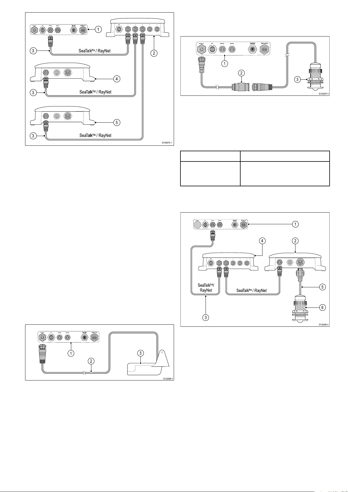
SeaTalk
hs
/ RayNet
SeaTalk
hs
/ RayNet
SeaTalk
hs
/ RayNet
D12975-1
1
2
4
5
3
3
3
1.Rearconnectorpanelofmultifunctiondisplay
2
D1225 6-1
1
3
D1225 7-1
1
2
3
1
2
SeaTalk
hs
/ RayNet
SeaTalkhs/
RayNet
3
6
5
4
D1225 8-1
(Sonarvariant).
2.Raymarine
®
networkswitch.
3.RayNetnetworkcables.
600wattsonar-compatiblesonartransducer
connectionviaoptionaladaptor—Sonarvariant
multifunctiondisplays
1.Rearconnectorpanelofmultifunctiondisplay
(Sonarvariant).
2.E66066adaptorcable.
3.Sonartransducer.
Transduceradaptorcable
CablePartnumber
0.5m(1.64ft)
E66066
transduceradaptor
cable
4.CP450CCHIRPsonarmodule
5.CP100DownVision
TM
orCP200SideVision
Sonartransducerconnection—Non-Sonar
TM
variantmultifunctiondisplays
sonarmodule
Compatiblesonartransducers
Themultifunctiondisplayiscompatiblewiththe
followingsonartransducers:
•Raymarine
•Raymarine
®
P48
®
P58
•MinnKotatransducersSonarvariantRaymarine
displaysonly),viaoptionalA62363adaptorcable.
•Any600wattsonar-compatibletransducer,via
optionalE66066adaptorcable.
Sonartransducerconnection—Sonarvariant
multifunctiondisplays
1.RearconnectorpanelofMFD(Non-sonar
variant).
2.Raymarine
connectingmorethanonedeviceusingSeaTalk
®
networkswitch(onlyrequiredif
hs
/RayNet).
1.Rearconnectorpanelofmultifunctiondisplay
(Sonarvariant).
2.Sonartransducercable.
3.RayNetcable.
4.Raymarine
®
sonarmodule.
5.Sonartransducercable.
6.Sonartransducer.
3.Sonartransducer.
Cablesandconnections63

MinnKotasonartransducerconnection
D1225 9-1
1
4
2
3
viaoptionaladaptorcable(Sonarvariant
multifunctiondisplaysonly)
1.RearconnectorpanelofMFD(Sonarvariant).
2.MinnKotatransduceradaptorcable.
3.MinnKotatransducercable.
4.MinnKotatransducer.
Sonarvariantmultifunctiondisplays
Thetablebelowdetailswhichmultifunctiondisplay
variantsfeatureabuilt-insonarmoduleandcanbe
connecteddirectlytocompatiblesonartransducers.
Non-sonar
variantsSonarvariants
DownVision
variants
•NoMFD(s)withaninternalsonarmodule,but
morethanoneCP300orCP450Csonarmodule.
ThisdoesNOTapplytoanysystemsthatdoNOT
includeaCP300orCP450Csonarmodule.
Note:Forsoftwaredownloadsandinstructions
onhowtoupdatethesoftwareforyourproduct(s),
visitwww.raymarine.com/software.
TM
a65a67a68
a65Wi-Fia67Wi-Fia68Wi-Fi
a75a77
a78
a75Wi-Fia77Wi-Fia78Wi-Fi
a95a97a98
a125a127a128
e7
e7D
c95c97
c125c127
e95e97
e125e127
e165
MinnKotatransduceradaptorcable
ConnectsaMinnKotasonartransducertoa
compatibleRaymarinemultifunctiondisplay.
CablePartnumber
1m(3.28ft)MinnKota
A62363
transduceradaptorcable
Importantsoftwarerequirementsformultiple
sonarsystems
Ifyoursystemincludesmorethanonesourceof
sonardatayoumustensurethatanyCP300or
CP450Csonarmodulesarerunningsoftwareversion
v4.04orlater.
Thisappliestosystemswhichinclude:
•AnynumberofMFD(s)withaninternalsonar
moduleplusaCP300and/orCP450Csonar
module;or
64aSeries/cSeries/eSeries

4.10Thermalcameraconnection
D12839-1
3
2
1
4
5
2
3
4
56
D1226 0-1
1
8
7
SeaTalk
hs
/ RayNet
SeaTalk
hs
/ RayNet
SeaTalk
hs
/ RayNet
YoucanconnectathermalcameratoyourNewc
SeriesorNeweSeriesmultifunctiondisplays.
Note:NewaSeriesdoesnotsupportthermal
cameras.
ThecameraisusuallyconnectedviaaRaymarine
networkswitch.Ifyouwanttousetheoptional
JoystickControlUnit(JCU)withthecamerathis
mustalsobeconnectedtothenetworkswitch.A
compositevideoconnectionisrequiredbetweenthe
cameraandthemultifunctiondisplay.
T200Seriesthermalcameraconnection
(JCU)isoptional,butcanbeusedinconjunction
withthemultifunctionaldisplaytocontrolthe
thermalcameraifrequired.
•“Dualpayload”thermalcamerasinclude2
independentlenses;1forthermal(infrared)and
1forvisiblelight.Ifyouonlyhave1displayyou
shouldonlyconnectthevideocablelabelled“VIS
/IR”(visiblelight/infrared)tothedisplay.Ifyou
have2ormoredisplaysyoushouldconnect1
cabletoeachdisplay.
•Youcanonlyviewthethermalcameraimageon
themultifunctiondisplaytowhichthecamerais
physicallyconnected.Ifyouwanttoviewthe
thermalcameraimageonmorethan1displayyou
mustobtainasuitablethird-partyvideodistribution
unit.
•Forfurtherinformationregardingthecamera's
installation(includingconnectionsandmounting),
refertotheinstallationinstructionsthataccompany
thecamera.
Thermalcameracables
1.T200Seriesxedmountthermalcamera.
2.Multifunctiondisplay .
3.PoweroverEthernet(PoE)Injector.
4.RayNettoRJ45SeaTalk
hs
adaptorcable.
5.Videocable.
T300/T400Seriesthermalcameraconnection.
Cablingrequirementsforthermalcameras.
Cameratonetworkswitch
Anetworkpatchcableisrequiredtoconnectthe
cameratothenetworkswitch.Theconnectionis
madebetweenthecameracabletailandthenetwork
switchviathecoupler(suppliedwiththecamera).
Networkpatchcablesareavailableinavarietyof
lengths.
JoystickControlUnit(JCU)
AnEthernet(withpower)cableisusedtoconnect
theJCU.TheJCUissuppliedwitha7.62m(25ft)
Ethernetcableforthisconnection.Ifyourequire
adifferentlengthcontactyourdealerforsuitable
cables.
PoweroverEthernet(PoE)injectortonetwork
switch
Anetworkpatchcableisrequiredforconnectingthe
PoEinjectortothenetworkswitch.Networkpatch
cablesareavailableinavarietyoflengths.
Videocables
1.Multifunctiondisplay
2.Raymarinenetworkswitch
toRayNetcable
3.JoystickControlUnit(JCU),optional
4.SeaT alk
hs
Pleasecontactyourdealerforsuitablecablesand
adaptors.
RaymarinerecommendstheuseofaBNC
terminatedRG5975ohm(orbetter)coaxialcable.
5.Ethernetcablecoupler.
Videocablesarenotsuppliedwiththeproduct.
6.PoE(PoweroverEthernet)injector(only
requiredifusingtheoptionalJCU).
7.Thermalcamera
8.Videoconnection
Importantnotes
•Youcancontrolthethermalcamerausingyour
multifunctionaldisplay.TheJoystickControlUnit
Cablesandconnections65

4.11IPCameraconnections
D12592-3
1
3
4
2
D12593-3
1
4
3
4
4
2
5
5
5
5
3 3
3
YoucanconnectIPcamerastoyourmultifunction
display.
CompatibleIPcamerasmustbeabletobe
conguredto:
•automaticallyassignanIPaddressviaDHCP
priortoconnectingtoyourmultifunctiondisplay
ornetwork.
•allowunauthenticated,anonymousONVIFaccess.
PleaserefertotheinstructionssuppliedwithyourIP
cameraforcongurationdetails.
Note:Theconnectionpanelonyourproductmay
lookslightlydifferentfromthatshown,depending
onvariant.Thenetworkconnectionmethod
remainsthesameforallproductsfeaturingRayNet
connectors.
IPcamera(s)canbeconnecteddirectlytothe
SeaTalk
hs
RayNetconnectoronyourmultifunction
display.
ItemDescription
1
Multifunctiondisplayrearconnectorpanel
2IPcamera
3RayNettoRJ45cable
4
SeaTalk
hs
crossovercoupler
ItemDescription
1
Multifunctiondisplay
2Raymarinenetworkswitch
3RayNettoRJ45adaptorcable
4
5
SeaTalk
IPCameras
hs
crossovercouplers
Note:a,candeSeriesmultifunctiondisplaysdo
notprovidepoweroverethernet(PoE);Connected
camerasmusthavetheirownpowersupply.
TipIfyourIPcamera(s)arenotdetectedbyyour
multifunctiondisplay,trypowercyclingtheIP
camera(s)whilstleavingyourmultifunctiondisplay
poweredup.
YoucanalsoconnectmultipleIPcamerasviathe
SeaTalk
66aSeries/cSeries/eSeries
hs
network

4.12Weatherreceiverconnection
RayNet
0
000
0
AUDIO
0
0
ANTENNA
NETWORK
0
POWER
0
0
D12902-2
1
2
1
2
3 4
D12741-1
3 2
D12742-1
4
1
5
4.13Fusionlinkconnection
YoucanconnectaSiriusXMweatherreceiverto
yourmultifunctiondisplay.
1.Raymarineweatherreceiver.
2.Multifunctiondisplay .
Theweatherreceivercanalsobeconnectedtoa
Raymarinenetworkswitch.
ForinformationonconnectinganSR50using
SeaTalk
ng
pleasereferto82257–SR50operation
whichcanbedownloadedfromtheRaymarine
website:www.raymarine.com.
YoucanconnectaFusion700seriesmarine
entertainmentsystemtoyourmultifunctiondisplay.
Directconnection
1.Multifunctiondisplay .
2.Fusionsystem.
3.RayNettoSeaTalk
hs
cable.
4.Fusionethernetconnector.
Directconnectionwithnetworkedmultifunction
displays
1.Fusionsystem.
2.Fusionethernetconnector.
3.RayNettoSeaTalk
hs
cable.
4.Directlyconnectedmultifunctiondisplay.
5.Networkedmultifunctiondisplays.
Note:TheFusionentertainmentsystemcanbe
controlledbyadirectlyconnectedmultifunction
displayorbyanetworkedmultifunctiondisplay.
Cablesandconnections67

Networkconnection
D12740-1
6
5
1
2
6
3 4
D1226 1-1
SeaTalk
ng
1
2
D1226 2-1
NMEA 0183
1 2
4.14GPSconnection
Dependingondisplayvariant,yourmultifunction
displaymayincludeaninternalGPSreceiver.If
requiredthemultifunctiondisplaycanalsobe
connectedtoanexternalGPSreceiver,using
SeaTalk
ng
orNMEA0183.
1.Networkswitch.
2.Fusionsystem.
3.RayNettoSeaTalk
GPSconnection—SeaT alk
ng
1.Multifunctiondisplay .
2.SeaT alk
ng
GPSreceiver.
GPSconnection—NMEA0183
hs
cable.
4.Fusionethernetconnector.
5.SecondFusionsystem(themultifunction
displaycanbeconnectedtomultipleFusion
entertainmentsystems).
6.Networkedmultifunctiondisplays.
Note:TheFusionentertainmentsystemcan
becontrolledbyanycompatiblenetworked
multifunctiondisplaywhenconnectedusinga
networkswitch.
1.Multifunctiondisplay .
2.NMEA0183GPSreceiver.
68aSeries/cSeries/eSeries

4.15GA150connection
D13069-1
21
1
3
2
4
D13074-1
a9xanda12xMFDsincludeaninternalGNSS(GPS
/GLONASS)receiver.TheGA150antennacan
beusedtoimprovetheGNSS(GPS/GLONASS)
receiver’sreception.
1.GA150antenna
2.a9xora12xvariantMFD
Forinstallationdetailsforyourexternalantenna,
refertothedocumentationthataccompaniedthe
antenna.
Note:
•TheBeidouGNSSissupportedbutnotcurrently
available.
•AGA150mustbeconnectedinordertoreceive
theBeidousystemwhenitbecomesavailable.
•Asoftwareupdatewillberequiredtoadd
supportforBeidouoncethesystemisavailable.
PleasecheckwithyourRaymarinedealerfor
furtherdetails.
Antennacablelength
TheGA150issuppliedwithatted10m(33ft.)
cable.Thelengthoftheantennacablecanbe
extendedifrequired.
Theantennacablelengthcanbeextendedbyupto
10m(33ft.)givingatotalmaximumcablelength
of20m(66ft.)
1.Fullyinserttheantenna’scableconnectorinto
theGA150connectorontherearofyourdisplay.
2.TurnthelockingcollarclockwiseuntilTIGHT.
3.Pushtoprotectivebootovertheconnectionon
thebackofthedisplay.
4.Usethesuppliedcabletietosecuretheprotective
bootovertheconnection.
50ohmcoaxialcableandreliableconnectors
(offeringprotectionagainstwateringress)mustbe
usedwhenextendingtheantennacable.
Note:Extendingthecablelengthbymorethan
therecommendedmaximumlengthwillresultin
signaldegradation.
Connectinganexternalantenna
FollowthestepsbelowtoconnecttheGA150
externalantennatoyoura9xora12xvariantMFD.
Cablesandconnections69

4.16AISconnection
D1226 3-1
SeaTalk
ng
2
1
NMEA0183 (38400)
NMEA 0183 (4800)
3
1
2
D1226 4-1
AcompatibleAIScanbeconnectedusingSeaT alk
orNMEA0183.
ConnectionusingSeaTalk
1.Multifunctiondisplay .
2.SeaT alk
ng
AISreceiver/transceiver.
ConnectionusingNMEA0183
ng
4.17Fastheadingconnection
ng
IfyouwishtouseMARP A(radartargetacquisition)
functionsonyourmultifunctiondisplayyouneed
either:
•Anautopilotconnectedtothemultifunctiondisplay
viaSeaTalk
connectedtothecoursecomputerandcalibrated
viathepilotcontrolhead;or:
•ARaymarineorthird-partyfastheadingsensor
connectedtothemultifunctiondisplayviaNMEA
0183.
Note:PleasecontactyourdealerorRaymarine
technicalsupportformoreinformation.
ng
orNMEA0183.Thecompassis
1.VHFradio.
2.AISunit.
3.Multifunctiondisplay .
70aSeries/cSeries/eSeries

4.18SeaTalk
00
D12176-4
12 V / 24 V dc
1
2
6
9
10
8
5
7
3
4
ng
connections
•Othersuitable12Vpowersupply.
ThedisplaycanconnecttoaSeaT alk
ThedisplaycanuseSeaTalk
•SeaTalk
•SeaTalk
ng
instruments
ng
autopilots
ng
tocommunicatewith:
ng
network.
•SeaTalkequipmentviatheoptionalSeaT alkto
SeaTalk
ng
converter
•NMEA2000equipmentviaoptionalDeviceNet
adaptorcables
TypicalSeaTalk
ng
system
Note:SeaT alk
ng
doesNOTsupplypowerto
multifunctiondisplaysandotherequipmentwitha
dedicatedpowersupplyinput.
1.SeaT alk
2.SeaT alk
3.iTC-5converter
ng
ng
instrument
pilotcontrolhead
4.Windtransducer
5.SeaT alk
ng
multifunctiondisplay
6.Powersupply
7.SeaT alk
ng
autopilot
8.iTC-5converter
9.Depthtransducer
10.Speedtransducer
FordetailsofSeaT alk
Chapter33Sparesandaccessories.
SeaTalk
TheSeaT alk
ng
powerrequirements
ng
busrequiresa12Vpowersupply.
ng
cablingpleasereferto
Powermaybeprovidedfrom:
•Raymarineequipmentwitharegulated12Vpower
supply(forexample,aSmartPilotSPXcourse
computer);or:
Cablesandconnections
71

4.19NMEA2000connection
NMEA 200012V
D1217 4-2
1
2
4
3
SeaTalk
ng
D1217 5-2
32
4
1
D1226 5-1
SeaTalk
ng
SeaTalk
1
2
SeaTalk
ng
3
4.20SeaTalkconnection
ThedisplaycanreceivedatafromNMEA2000
devices(e.g.datafromcompatibleengines).The
NMEA2000connectionismadeusingSeaT alk
andappropriateadaptorcables.
YoucanEITHER:
•UseyourSeaT alk
ng
backboneandconnecteach
NMEA2000deviceonaspur,OR
•connectthedisplayonaspurintoanexisting
NMEA2000backbone.
Important:Youcannothave2backbones
connectedtogether.
ConnectingNMEA2000equipmenttothe
SeaTalk
ng
backbone
YoucanconnectSeaT alkdevicestoyour
multifunctiondisplayusingtheoptionalSeaTalkto
ng
SeaTalk
ng
converter.
1.SeaT alkdevice.
2.SeaT alktoSeaT alk
ng
converter.
3.Multifunctiondisplay .
1.12Vsupplyintobackbone.
2.SeaT alk
3.SeaT alk
ng
backbone.
ng
toDeviceNetadaptorcable.
4.NMEA2000equipment.
ConnectingthedisplaytoanexistingNMEA2000
(DeviceNet)backbone
1.Multifunctiondisplay .
2.SeaT alk
ng
toDeviceNetadaptorcable.
3.DeviceNetbackbone.
4.NMEA2000equipment.
72
aSeries/cSeries/eSeries

4.21NMEA0183connection
D12266-3
61 2 3 4 5
11
7 8 9 10
12
NMEA DEVICE
4800 / 38400 baud
NMEA DEVICE
4800 / 38400 baud
NMEA0183devicescanbeconnectedtocompatible
multifunctiondisplays(MFDs)usingthepowerand
datacable.
Note:T oconnectanNMEA0183devicetoana6x
ora7xMFDaSeaT alk
mustbeusedtoconverttheSeaT alk
toNMEA0183messages.
ng
toNMEA1083converter
ng
messages
ItemDevice
1White1InputPositive
Multifunction
2
display
3Yellow1
4Brown1
5
Cable
colorPort
Green
Orange/
Input/
output
1InputNegative
Output
Output
2InputPositive
white
Positive
(+)/negative(-)
Positive
Negative
6
Orange/
2InputNegative
green
7
NMEA
device
8
9
10
NMEA
11
device
12
**Output
**Output
**
**
**Output
**Output
InputPositive
InputNegative
Note:*Refertoinstructionsprovidedwiththe
NMEA0183device.
NMEA0183cable
YoucanextendtheNMEA0183wireswithinthe
suppliedpoweranddatacable.
Datacableextension
Totallength(max)Cable
Upto5mHighqualitydatacable:
Positive
Negative
Positive
Negative
NMEA0183devicesareconnectedusingthepower
anddatacablesuppliedwithcompatibleMFDs.
2NMEA0183portsareavailable:
•Port1:Inputandoutput,4800or38400baudrate.
•Port2:Inputonly,4800or38400baudrate.
Note:Thebaudrateyouwanttouseforeachport
inputmustbespeciedintheSystemSettings
menu(Homescreen>Set-up>SystemSettings
>NMEASet-up>NMEAInputPort).
Note:ForPort1,boththeinputandoutput
communicateatthesamebaudrate.Forexample,
ifyouhaveoneNMEA0183deviceconnectedto
thedisplay'sPort1INPUT ,andanotherNMEA
0183deviceconnectedtothedisplay'sPort1
OUTPUT,bothNMEAdevicesmustbeusingthe
samebaudrate.
Youcanconnectupto4NMEA0183devicesto
thedisplay'sNMEA0183OUTPUT(Port1).You
canconnectatotalof2NMEA0183devicestothe
display'sNMEA0183INPUTports.
•2xtwistedpairwithoverall
shield.
•50to75pF/mcapacitance
coretocore.
Cablesandconnections73
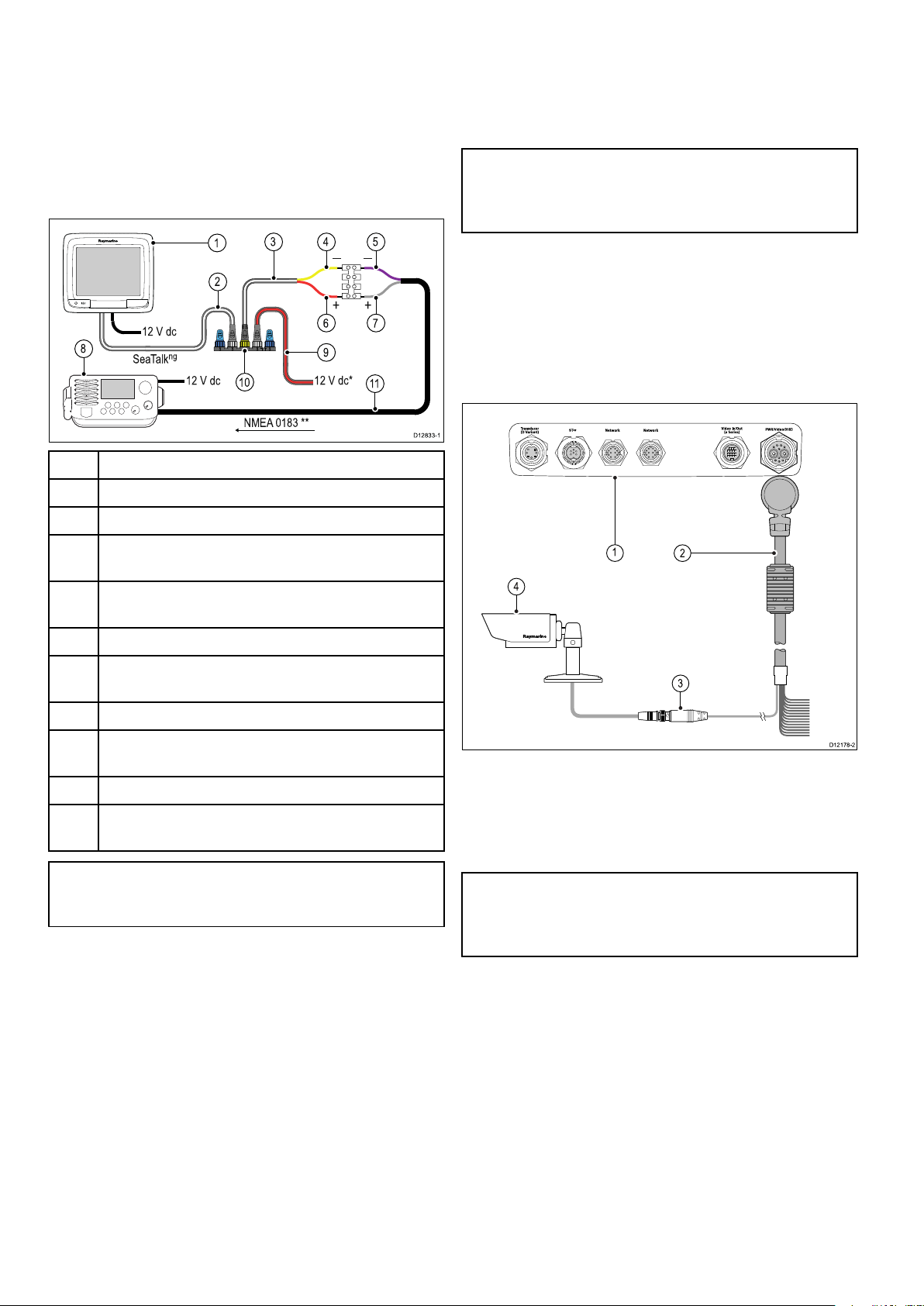
4.22a6xanda7xtoNMEA0183DSC
12 V dc
+
— —
+
43 5
2
8
11
D12833-1
10
1
SeaTalk
ng
12 V dc*
12 V dc
NMEA 0183 **
6 7
9
D1217 8-2
1
2
4
3
VHFradioconnection
Toconnectana6xanda7xvariantMFDstoan
NMEA0183DSCradioaSeaTalk
convertermustbeusedtoconverttheSeaT alk
messagestoNMEA0183messages.
TheMFDandconvertermustbeconnectedtothe
sameSeaTalk
ng
backbone.
ng
toNMEA0183
4.23Camera/Videoconnection
Acameraoravideodevicecanbeconnecteddirectly
toNewcSeriesandNeweSeriesmultifunction
displaysusingthevideoconnectoronthepowerand
ng
datacable.
Note:Videodevicescannotbedirectlyconnected
toNewaSeriesmultifunctiondisplays.Forcamera
connectionstoaNewaSeriesdisplaypleaserefer
totheIPcameraconnectionsection.
Examplesofvideosourcesthatyoucanconnectto
thedisplayinclude:
•Videocamera.
•Thermalcamera.
•DVDplayer.
•Portabledigitalvideoplayer.
1
2
3
4
a6x/a7xMFD
SeaTalk
SeaTalk
ng
spurcable
ng
toNMEA0183barewiresspurcable
ConverterNMEA0183negativeconnection(yellow
wire)
5
NMEA0183deviceinputnegativeconnection(purple
wire)
6
7
ConverterNMEA0183positiveconnection(redwire)
NMEA0183deviceinputpositiveconnection(grey
wire)
8
9
10
11
NMEA0183DSCVHFRadio
SeaTalk
toanexistingpoweredSeaTalk
ng
powercable(onlyrequiredifnotconnecting
ng
backbone.
Converter
NMEA0183connection(usecablesuppliedwithVHF
radio)
Note:TheconnectionattheVHFradiomustbeto
theNMEA0183inputonly .Itisauni-directional
(one-way)connection.
1.Rearconnectorpanelofmultifunctiondisplay.
2.Poweranddatacable.
3.BNCvideoconnector(input1).
4.Videosource—forexample,videocamera.
Note:T olistentoamovie’saudiotrack,any
connectedDVDordigitalvideoplayerwillrequire
speakerstobeconnectedtotheplayersaudio
output.
74
aSeries/cSeries/eSeries
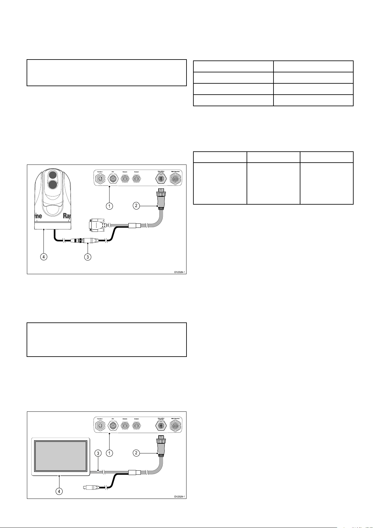
4.24Camera/videoin-outconnection
D1232 8-1
1
2
4
3
D1232 9-1
1
2
4
3
2.Videoaccessorycable.
Acamera/videodeviceorexternaldisplaycanbe
connectedtoNeweSeriesmultifunctiondisplays
(excludingthee7/e7D)usingthededicatedvideo
in/outconnector.
Note:NewaSeriesandNewcSeriesmultifunction
displaysdonothaveadedicatedvideoin/out
connector.
VideoIn
Examplesofvideoinputsourcesthatyoucan
connecttothedisplayinclude:
•Videocamera.
•Thermalcamera.
•DVDplayer.
•Portabledigitalvideoplayer.
3.VGAcabletoexternaldisplay .
4.Externaldisplay .
Videospecication
SignaltypeComposite
Format
PALorNTSC
ConnectortypeBNC(female)
Outputresolution
720p
e9ande12Videocables
Thefollowingvideocableisrequiredforthevideoin
/outconnectoronthee95/e97/e125/e127variant
multifunctiondisplays.
PartnumberDescriptionNotes
R70003
5m(16.4ft.)Video
cablefore9and
e12(1xvideoin
and1xvideoout
VGA)
1.Rearconnectorpanelofmultifunctiondisplay.
2.Videoaccessorycable.
3.BNCvideoconnector(input2).
4.Thermalcamera.
Note:T olistentoamovie’saudiotrack,any
connectedDVDordigitalvideoplayerwillrequire
speakerstobeconnectedtotheplayersaudio
output.
Videoout
Examplesofvideooutputdevicesthatyoucan
connecttothedisplayinclude:
•HDTVwithVGAinput.
•VGAmonitor.
1.Rearconnectorpanelofmultifunctiondisplay.
Cablesandconnections75

4.25Mediaplayerconnection
D1216 4-2
1 32
1229 3-1
1
32 4 5
Youcanuseyourmultifunctiondisplaytowirelessly
controlaBluetooth-compatiblemediaplayer(such
asasmartphone).
Themediaplayermustbecompatiblewiththe
Bluetooth2.1+EDRpowerclass1.5(supported
prole:AVRCP1.0)orhigher.
1.Multifunctiondisplay .
2.Bluetoothconnection.
3.Bluetooth-compatiblemediaplayer.
Tousethisfeatureyoumustrst:
•EnableBluetoothintheSystemSettingsonthe
multifunctiondisplay.
6.Onthemultifunctiondisplay ,selectOKinthe
messagedialog.
Themultifunctiondisplaywillsearchforactive
Bluetoothdevices.
7.SelectStopDiscoverywhenyourdevice
appearsinthelist.
8.Selectthemediaplayerdeviceinthelist.
Apairingrequestmessageisdisplayedonthe
externalmediadevice.
9.Ontheexternalmediadevice,selectPair
(orequivalent)toacceptthepairingrequest
message.
Themultifunctiondisplayshowsamessage
askingyoutoconrmthePairingcode.
10.Ifthepairingcodedisplayedonthemultifunction
displaymatchesthecodedisplayedonthe
externalmediadevice,selectOkonthe
multifunctiondisplay .IfthecodedoesNOT
match,repeatsteps4to8.
11.Ifthepairingwassuccessfulthemultifunction
displaywillconrmthepairing.
Theexternalmediadeviceisnowpairedwiththe
multifunctiondisplay.
•EnableBluetoothonthemediaplayerdevice.
•Pairthemediaplayerdevicewiththemultifunction
display.
•EnableAudioControlintheSystemSettingson
themultifunctiondisplay.
•ConnectanRCU-3remoteandassigntheshortcut
keytoStart/Stopaudioplayback(Onlyrequiredon
aNewcSeriesdisplay).
Note:Ifyourmediaplayerdoesnotincludebuilt-in
speakersitmaybenecessarytoconnectthemedia
player'saudiooutputtoanexternalaudiosystem
orapairofheadphones.Formoreinformation
refertotheinstructionsthataccompanythemedia
playerdevice.
EnablingBluetooth
Withthehomescreendisplayed:
1.SelectSet-up.
2.SelectSystemSettings.
3.SelectWirelessConnections.
4.SelectBluetooth>On.
Enablingaudiocontrol
Withthehomescreendisplayed:
1.SelectSet-up.
2.SelectSystemSettings.
3.SelectWirelessConnections.
4.SelectConnectionManager.
5.Selectthemediaplayerdeviceinthelist.
6.SelectAudioControl>On.
Mediaplayercontrols
Touchscreenmultifunctiondisplaysenableyouto
usetheon-screenmediaplayercontrolstocontrol
theaudioplayingonyourexternalmediaplayer.
PairingaBluetoothmediaplayer
WiththehomescreendisplayedandBluetoothturned
on:
1.SelectSet-up.
2.SelectSystemSettings.
3.SelectWirelessConnections.
4.SelectNewBluetoothConnection.
Amessageisdisplayedpromptingyoutoput
yourmediaplayerdeviceintodiscoverymode.
5.EnsureBluetoothisenabledonyourexternal
mediaplayerdeviceandensureitisreadyto
bepaired.Formoreinformation,consultthe
instructionsthataccompanythedevice.
76aSeries/cSeries/eSeries
1.T ouchthisicontodisplaytheaudiocontrols.
2.Previoustrack.
3.Playtrack.
4.Pausetrack.
5.Nexttrack.
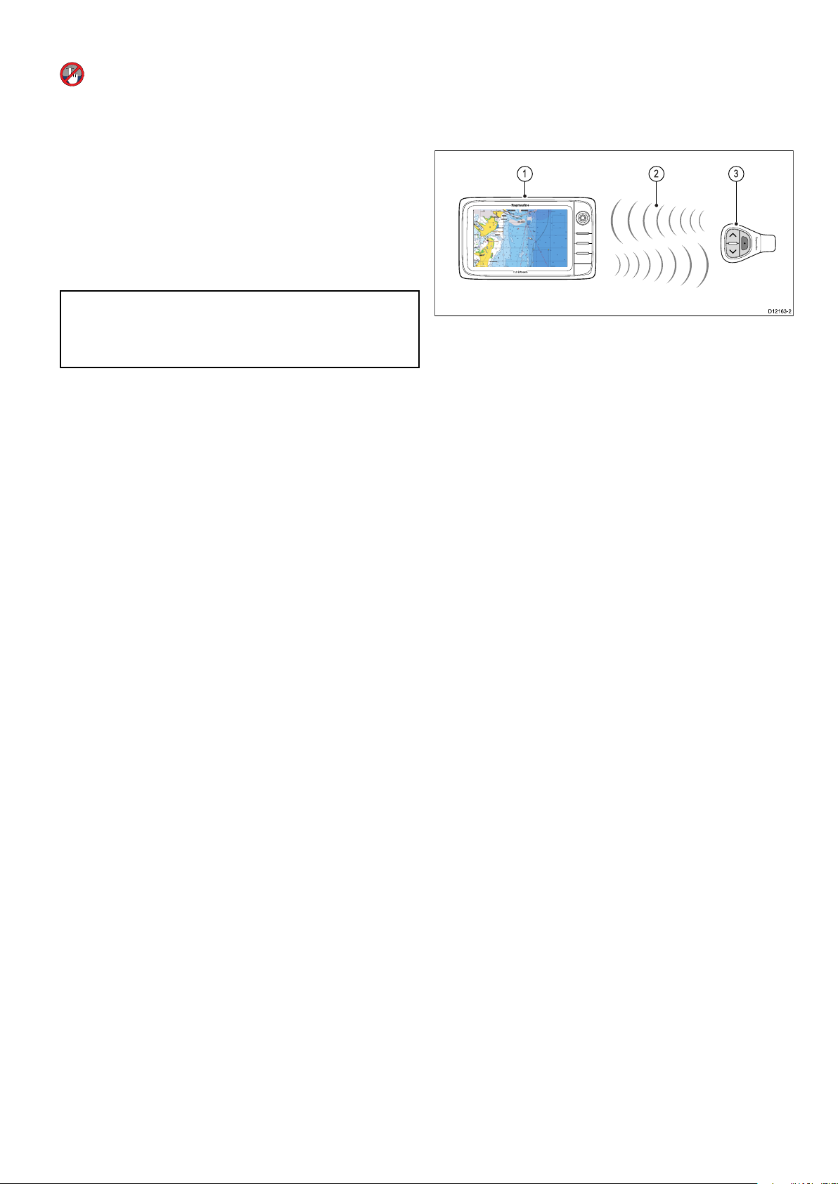
SelectingBackwillhidetheaudiocontrols.
D1216 3-2
1 32
Mediaplayercontrolsusingaremote
control
YoucancontrolaudiowirelesslyusingaRaymarine
RCU-3remotecontrolunit.
TheShortcutkeyontheRCU-3mustbesetto
Start/Stopaudioplayback,refertotheUsinga
Remotecontrolsectionforfurtherdetails.
1.PressUParrowfornexttrack.
2.PressDOWNarrowforprevioustrack.
3.PressSHORTCUTbuttontoplay/pauseaudio.
Note:OnNewcSeriesmultifunctiondisplays,
whilsttheaudiocontrolsappearonthescreenyou
cannotinteractwiththem.Tocontrolaudioyou
mustuseaconnectedRCU-3.
UnpairingaBluetoothdevice
Ifyouareexperiencingproblemswhenattemptingto
useaBluetoothdevicewiththemultifunctiondisplay
itmaybenecessarytounpairthedevice(andany
otherpairedBluetoothdevices)andthenretrythe
pairingprocedure.
Withthehomescreendisplayed:
1.SelectSet-up.
2.SelectSystemSettings.
3.SelectWirelessConnections.
4.SelectConnectionManager.
5.Selectthemediaplayerdeviceinthelist.
6.SelectUnpair/Forgetthisdevice.
4.26Bluetoothremotecontrol connection
Youcancontrolthemultifunctiondisplaywirelessly
usingaRaymarineremotecontrolunit.
TheremotecontrolusesaBluetoothwireless
connection.
1.Multifunctiondisplay .
2.Bluetoothconnection.
3.RaymarineBluetoothremotecontrol(for
example,RCU-3).
Tousetheremotecontrolyoumustrst:
•EnableBluetoothintheSystemSettingsonthe
multifunctiondisplay.
•Pairtheremotecontrolunitwiththemultifunction
display.
Operatingprinciples
Remotecontroloperatingprinciples.
•Only1multifunctiondisplaymaybeoperatedby
aremotecontrolunitatanyonetime.Y oucannot
pairamultifunctiondisplaytomorethan1remote
controlatthesametime.
•The3buttonsontheremotecontrolunithave
differentfunctionsdependingontheCONTEXTin
whichyouareusingit.Forexample,inthechart
applicationthebuttonscontroldifferentfunctions
thantheydointhehomescreen.
•Allfunctionsareaccessedusingacombinationof
the3buttons.Forsomefunctionsyoumustpress
abuttonMOMENTARILY .Y oucanalsoHOLD
abuttonforcontinuousresponse(forexample,
continuousranginginthechartapplication).
•Themainmethodsofoperationinvolvetheuse
oftheUPandDOWN“arrow”buttonstohighlight
differenton-screenoptions.TheSHORTCUT
buttonisusedtoselect(execute)them.
•Duringthepairingprocessyoumustdenewhich
ofthearrowbuttonsyouwanttobethe“UP”
button.
•TheSHORTCUTbuttoniscustomizableandcan
beconguredtooperateoneofanumberof
functions,usingtheSystemSettingsmenuon
yourmultifunctiondisplay.
Cablesandconnections
PairingtheremoteandconguringtheUP
andDOWNbuttons
Theremotecontrolunitmustbe“paired”withthe
multifunctiondisplaythatyouwanttocontrol.On
yourmultifunctiondisplay ,withthehomescreen
displayed:
77

1.SelectSet-up.
2.SelectSystemSettings.
3.SelectWirelessConnections.
4.SelectBluetooth>On.
5.SelectNewBluetoothConnection.
Apop-upmessagewillbedisplayedtoconrm
thatthedeviceyouareconnectingtois
discoverable.
6.SelectOktoconrm.
Alistofdiscovereddevicesisdisplayed.
7.Onyourremotecontrolunit,holddowntheUP
andDOWNbuttonstogetherfor10seconds.
8.Selecttheremotecontrolunitinthelistof
devices.
9.Whenprompted,pressthearrowbuttononyour
remotethatyouwishtobeconguredastheUP
button.Theotherarrowbuttonwillautomatically
beconguredastheDOWNbutton.
Ifthepairingwassuccessfula“PairingSuccess”
messagewillbedisplayed.Ifa“PairingFailure”
or“PairingTimeout”messageisdisplayed,
repeatsteps1to8.
CustomizingtheSHORTCUTbutton
Onyourmultifunctiondisplay,withthehomescreen
displayed:
1.SelectSet-up.
2.SelectSystemSettings.
3.SelectExternalDevices.
4.SelectRemoteControl.
5.SelectCustomizeshortcutkey.
6.Selectthefunctionthatyouwanttoassigntothe
SHORTCUTkey.
78aSeries/cSeries/eSeries

4.27Remotecontrolfunctions
ange
Buttons
Pair
Selec t
or
D12051-2
Arrow buttons
Shortcut button
ButtonApplicationwherefunctionavailable:
Defaultfunctions:Chart
Range/zoom.•PressUPorDOWN
arrowformomentary
response.
•HoldUPorDOWN
arrowforcontinuous
response.
Openhomescreen.Shortcut:Hold
Selectapplication
inhomescreen
(inleft-to-right,
top-to-bottomorder).
Togglemenuitemsand
optionsindialogsand
prompts(inleft-to-right,
top-to-bottomorder).
•PressUPorDOWN
arrowformomentary
response.
•HoldUPorDOWN
arrowforcontinuous
response.
•PressUPorDOWN
arrowformomentary
response.
•HoldUPorDOWN
arrowforcontinuous
response.
Radar
Fishnder
WeatherHome-
screen
Placewaypointat
Shortcut
vesselposition.
Mediaplayercontrol
(requiresaBluetooth
mediaplayerpaired
tothemultifunction
display).
•PressUP/DOWN
arrowfornext/
previoustrack.
•PressSHORTCUT
buttonforplay/
pause.
Cablesandconnections79

Customizablefunctions:
>
10 Minutes
=
10
15
20
25
30
Minutes
35
40
45
50
55
60
5
=
3 Seconds
10
15
20
25
30
Seconds
35
40
45
50
55
60
5
Openhomescreen.SHORTCUT
ButtonApplicationwherefunctionavailable:
Switchactive
SHORTCUT
application(only
availablewhenmultiple
applicationsare
displayed).
ReconnectingtheRCU
1.WhenyoupairtheRCU-3withamultifunction
displayawirelessconnectionisestablished.
2.Whenyoupoweroffthemultifunctiondisplay
itlosesitsconnectionwiththeRCU-3after10
minutes.
3.T orestoretheconnectionbetweenthe2units,
pressandholdanybuttonontheRCU-3forat
least3seconds.
Note:Youwillalsoneedtoreconnectthe
RCU-3asdescribedaboveifyoudisableand
thenre-enabletheBluetoothconnectiononthe
multifunctiondisplayatanytime.
80aSeries/cSeries/eSeries
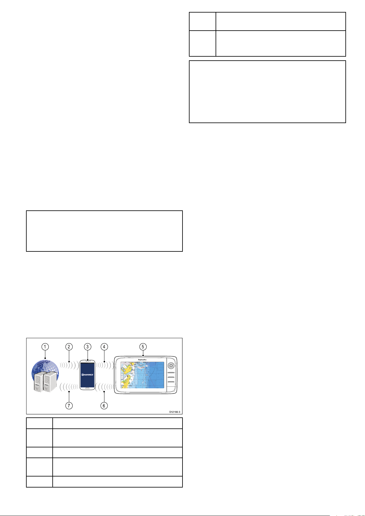
4.28WiFiconnections
D12166-3
67
1 2 4 53
Raymarinemobileappconnection
Youcanusecompatibletabletandsmartphone
devicesasawirelessrepeatdisplayorremote
controlforyourmultifunctiondisplay.
Raymarineappsallowyoutostreamand/orcontrol,
remotelywhatyouseeonyourmultifunctiondisplay
toacompatibledevice,usingaWi-Ficonnection.
Tousethisfeatureyoumustrst:
•Ensureyourdeviceiscompatiblewiththeappyou
wishtouse.
•DownloadandinstalltherelevantRaymarineapp,
availablefromtherelevantmarketstore.
•EnableWi-FiintheSystemSettingsonthe
multifunctiondisplay.
•EnableWi-Fionyourcompatibledevice.
•SelecttheRaymarineWi-Ficonnectionfromthe
listofavailableWi-Finetworksonyourcompatible
device.
•EnabletherelevantMobileappintheSystem
Settingsmenuonthemultifunctiondisplay.
Note:ThemultifunctiondisplayactsasaWi-Fi
accesspoint.Ifyourdevicealreadyconnectsto
anaccesspointfore-mailandinternetyoumust
revertyouraccesspointbacktoregainaccessto
e-mailsandinternet.
6
*UploadSonarLogsandCommunityeditsto
mobiledevice(Wi-FiconnectiontoMFDrequired)
7
**UploadSonarLogsandCommunityedits
anonymouslytoNavionicsservers(internet
connectionrequired)
Note:
*T oparticipateinNavionicsSonarCharts,Sonar
loggingmustbeenabledonyourMFD.SonarLogs
canbeenabledfromtheChartapplicationmenu:
Menu>Depth&Contour>SonarLogs.
**TheSonarlogsshallbeuploadedtoNavionics
serversanonymously.
Tousethisfeatureyoumustrst:
1.DownloadandinstalltheNavionicsMobile
Marineapp,availablefromtherelevantapp
store.
2.SubscribetoNavionicsFreshestData.
3.DownloadFreshestdatatoyourmobiledevice.
4.EnableWi-FiintheSystemSettingsontheMFD.
5.EnableWi-Fionyourmobiledevice.
6.SelecttheMFDWi-Ficonnectionfromthelistof
availableWi-Finetworksonyourmobiledevice.
Navionicsmobilemarineapp
Youcanwirelesslysynchronizedatabetweenyour
multifunctiondisplay(MFD)andamobiledevicethat
isrunningtheNavionicsmobilemarineapp.
ThesynchronizationdownloadsNavionicsFreshest
DatafromyourmobiledevicetoyourMFD
anduploadssonarlogsfromyourMFDtoyour
mobiledevice.Waypointsandroutescanalsobe
synchronizedbetweenyourmobiledeviceandMFD.
1Navionicsservers
2DownloadNavionicsFreshestDatatomobile
3MobiledevicerunningNavionicsmobileapp
device(internetconnectionrequired)
4
DownloadNavionicsFreshestDatatoMFD(Wi-Fi
connectiontoMFDrequired)
5
Cablesandconnections81
MFD

82aSeries/cSeries/eSeries

Chapter5:Mounting
Chaptercontents
•5.1Mounting-aSeriesonpage84
•5.2Mounting-cSeriesandeSeriesonpage86
Mounting
83

5.1Mounting-aSeries
D12585-2
0
D1258 8-1
0
0
0
0
0
0
D12578-2
Mounting
thedisplaycanbesurfacemounted.
Beforemountingtheunit,ensurethatyouhave:
•Selectedasuitablelocation.
•Identiedthecableconnectionsandroutethatthe
cableswilltake.
10.Slidetheunitintoplaceandsecureusingthe
providedxings.
Note:Thesuppliedgasketprovidesaseal
betweentheunitandasuitablyatandstiff
mountingsurfaceorbinnacle.Thegasketshould
beusedinallinstallations.Itmayalsobe
necessarytouseamarine-gradesealantifthe
mountingsurfaceorbinnacleisnotentirelyatand
stifforhasaroughsurfacenish.
•Detachedthefrontbezel.
1.Checktheselectedlocationfortheunit.Aclear,
atareawithsuitableclearancebehindthepanel
isrequired.
2.Drillorknockoutthe4mountingholesontheunit
Bracket(trunnion)mounting
Thedisplaycanbemountedonatrunnionbracket.
Beforemountingtheunitensurethatyouhave:
•Selectedasuitablelocation.
•Identiedthecableconnectionsandroutethatthe
cableswilltake.
•Attachedthefrontbezel.
3.Fixtheappropriatecuttingtemplatesupplied
withtheproduct,totheselectedlocation,using
maskingorself-adhesivetape.
4.Usingasuitableholesaw(thesizeisindicated
onthetemplate),makeaholeineachcornerof
thecut-outarea.
5.Usingasuitablesaw,cutalongtheinsideedge
ofthecut-outline.
6.Ensurethattheunittsintotheremovedarea
andthenlearoundtheroughedgeuntilsmooth.
7.Drill4holesasindicatedonthetemplateto
acceptthesecuringscrews.
8.Placethegasketontothedisplayunitandpress
rmlyontotheange.
9.Connectthepower,dataandothercablestothe
unit.
84aSeries/cSeries/eSeries
1.Markthelocationofthemountingbracketscrew
holesonthechosenmountingsurface.
2.Drillholesforthescrewsusingasuitabledrill,
ensuringthereisnothingbehindthesurfacethat
maybedamaged.
3.Usethexingssuppliedwiththemounting
brackettoattachsecurely.
4.Attachthedisplaytothemountingbracket.
Frontbezel
Attachingthefrontbezel
Thefollowingprocedureassumesthattheunithas
alreadybeenmountedinposition.

1.Carefullyliftoneedgeofthescreenprotection
D1258 6-1
D
1258 4-1
0
1
1
2222
1212121
2
lm,sothatitisaccessibleforremovingwhen
unitinstallationiscomplete.
2.Ensurethememorycardslotdoorisintheopen
position.
3.Orientatethebottom-rightsideofthebezelunder
thelipofthechartcarddoorandplacethebezel
overthefrontofthedisplay,ensuringthatthe
clipsalongthebottomedgeofthebezellatch
intoposition.
Important:Usecarewhenremovingthebezel.
Donotuseanytoolstoleverthebezel;doingso
maycausedamage.
4.Ensurethebezeliscorrectlyalignedwiththe
display,asshown.
5.Applyrmbutevenpressuretothebezelalong
the:
i.Outeredges-workfromthesidesupwards
andthenalongthetopedge,toensurethatit
clipssecurelyintoposition.
ii.Inneredges-particularlyalongthechartcard
dooredge,toensurethatthebezelsitsat.
6.CheckthatthePowerbuttonandchartcarddoor
arefreetooperate.
Removingthefrontbezel
Beforeproceedingensurethememorycardslotdoor
isopen.
1.Placebothyourthumbsontheupperleftedge
ofthedisplay,atthepositionsindicatedinthe
diagramabove.
2.Placeyourngersunderneaththebezel,atthe
positionsindicatedinthediagramabove.
3.Inasinglermmotion,applypressuretothe
outeredgeofthedisplaywithyourthumbsand
pullthebezeltowardsyouusingyourngers.
Thebezelshouldnowcomeawayfromthedisplay
easily.
Mounting
85

5.2Mounting-cSeriesandeSeries
D1218 4-3
e7 / e7D
1
3
2
D12271-2
Removingtherearbezel
Youmustremovetherearbezelbeforesurface
mountingthedisplay.
Note:Thesestepsdonotapplytothee165asit
doesnotrequirearearbezel.
1.Removethefrontbezel.Refertotheseparate
instructionsprovidedforthatprocedure.
2.Removethescrewsthatsecurethebezeltothe
display(onlyrequiredfore7ande7D).
3.Carefullyremovethebezelfromtherearofthe
display,pullingthebezelgentlyalongthe:
i.Outeredges-workfromthesidesupwards
andthenalongthetopedge,ensuringthatthe
clipsarefullyreleasedfromthedisplay.
ii.Inneredges-ensurethatthebezelis
completelyremovedfromthedisplay.
Note:Onlythee7ande7Dhavexingscrewsfor
therearbezel,othermultifunctiondisplayvariants
haveclipswhichholdtherearbezelinplace.
Surfacemounting
Thedisplaycanbesurfacemounted.
Beforemountingtheunit,ensurethatyouhave:
•Selectedasuitablelocation.
1.Checktheselectedlocationfortheunit.Aclear,
atareawithsuitableclearancebehindthepanel
isrequired.
2.Fixtheappropriatecuttingtemplatesupplied
withtheproduct,totheselectedlocation,using
maskingorself-adhesivetape.
3.Usingasuitableholesaw(thesizeisindicated
onthetemplate),makeaholeineachcornerof
thecut-outarea.
4.Usingasuitablesaw,cutalongtheinsideedge
ofthecut-outline.
5.Ensurethattheunittsintotheremovedarea
andthenlearoundtheroughedgeuntilsmooth.
6.Drill4holesasindicatedonthetemplateto
acceptthexings.
7.Placethegasketontothedisplayunitandpress
rmlyontotheange.
8.Connectthepower,dataandothercablestothe
unit.
9.Slidetheunitintoplaceandsecureusingthe
xingsprovided.
Note:Thesuppliedgasketprovidesaseal
betweentheunitandasuitablyatandstiff
mountingsurfaceorbinnacle.Thegasketshould
beusedinallinstallations.Itmayalsobe
necessarytouseamarine-gradesealantifthe
mountingsurfaceorbinnacleisnotentirelyatand
stifforhasaroughsurfacenish.
•Identiedthecableconnectionsandroutethatthe
cableswilltake.
•Detachedthefrontbezel.
Attachingtherearbezel
Therearbezelmustbettedifyouwishtousea
mountingbrackettomounttheunit.
Note:Thesestepsdonotapplytothee165asit
doesnotrequirearearbezel.
1.Removethefrontbezel.Refertotheseparate
instructionsprovidedforthatprocedure.
2.Placethebezelovertherearofthedisplay,
ensuringthatitiscorrectlyalignedwiththe
display.Applyrmbutevenpressuretothebezel
alongthe:
86aSeries/cSeries/eSeries

i.Outeredges-workfromthesidesupwards
D1218 3-3
e7 / e7D
1
2
3
D12273-2
andthenalongthetopedge,toensurethatit
clipssecurelyintoposition.
ii.Inneredges-ensurethatthebezelsitsat
againsttheunit.
3.Usethesuppliedscrewstosecurethebezelto
thedisplay(e7ande7Donly).
Bracket(trunnion)mounting
Thedisplaycanbemountedonatrunnionbracket.
Note:Themountingbracketissuppliedwiththe
e7ande7Ddisplayvariants,forallotherdisplay
variantsthemountingbracketisanoptional
accessorySeetheSparesandAccessories
sectionofthismanualfordetails.
Beforemountingtheunitensurethatyouhave:
•Selectedasuitablelocation.
•Identiedthecableconnectionsandroutethatthe
cableswilltake.
•Attachthefrontbezel.
1.Markthelocationofthemountingbracketscrew
holesonthechosenmountingsurface.
2.Drillholesforthexingsusingasuitabledrill,
ensuringthereisnothingbehindthesurfacethat
maybedamaged.
3.Usethexingssuppliedwiththemounting
brackettoattachsecurely.
4.Attachthedisplayunittothemountingbracket.
Frontbezel
Attachingthefrontbezel
Thefollowingprocedureassumesthattheunithas
alreadybeenmountedinposition.
1.Carefullyliftoneedgeofthescreenprotection
lm,sothatitisaccessibleforremovingwhen
unitinstallationiscomplete.
2.Ensurethememorycardslotdoorisintheopen
position.
3.Orientatethebottom-rightsideofthebezelunder
thelipofthechartcarddoorandplacethebezel
overthefrontofthedisplay,ensuringthatthe
clipsalongthebottomedgeofthebezellatch
intoposition.
Mounting
87

D1227 4-1
4.Ensurethebezeliscorrectlyalignedwiththe
D1227 5-1
2
1
2
1
display,asshown.
5.Applyrmbutevenpressuretothebezelalong
the:
i.Outeredges-workfromthesidesupwards
andthenalongthetopedge,toensurethatit
clipssecurelyintoposition.
ii.Inneredges-particularlyalongthechartcard
dooredge,toensurethatthebezelsitsat.
6.Checkthatallcontrolbuttonsarefreetooperate.
2.Placeyourngersunderneaththebezel,atthe
positionsindicatedinthediagramabove.
3.Inasinglermmotion,applypressuretothe
outeredgeofthedisplaywithyourthumbsand
pullthebezeltowardsyouusingyourngers.
Thebezelshouldnowcomeawayfromthedisplay
easily.
Removingthefrontbezel
Beforeproceedingensurethememorycardslotdoor
isopen.
Important:Usecarewhenremovingthebezel.
Donotuseanytoolstoleverthebezel;doingso
maycausedamage.
1.Placebothyourthumbsontheupperleftedge
ofthedisplay,atthepositionsindicatedinthe
diagramabove.
88aSeries/cSeries/eSeries

Chapter6:Gettingstarted
Chaptercontents
•6.1Displaypoweronpage90
•6.2aSeriesControlsonpage90
•6.3e7/e7DControlsonpage91
•6.4c95/c97/c125/c127/e95/e97/e125/e127/e165Controlsonpage91
•6.5Homescreenoverview—T ouchonlydisplaysonpage93
•6.6Homescreenoverview—cSeries/eSeriesonpage93
•6.7Pagesonpage95
•6.8Applicationsonpage97
•6.9Splitscreencontrolsonpage98
•6.10Screenoverviewonpage99
•6.11Basictouchscreenoperationsonpage102
•6.12Multi-Touchgesturesonpage103
•6.13Initialsetupproceduresonpage103
•6.14GPSStatusonpage106
•6.15Enablingautopilotcontrolonpage108
•6.16Engineidenticationonpage109
•6.17EnablingAISfunctionsonpage1 11
•6.18Sharedpreferencesonpage1 1 1
•6.19Softwareupdatesonpage112
•6.20Learningresourcesonpage1 13
Gettingstarted
89
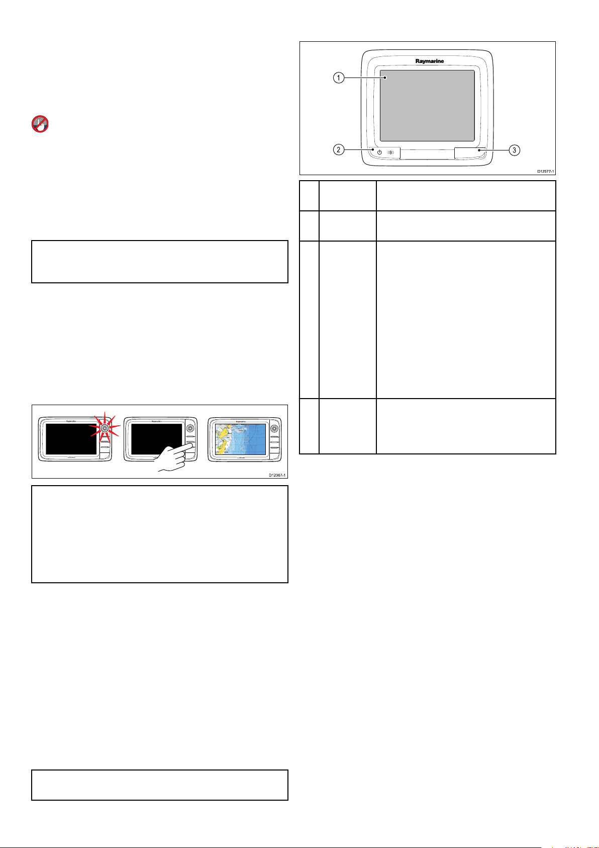
6.1Displaypower
D1236 7-1
D1257 7-1
3
1
2
Poweringthedisplayon
1.PressthePOWERbuttononthedisplay.
2.SelectAccepttoacknowledgethedisclaimer
message.
Poweringthedisplayon
1.PressthePOWERbutton.
2.PresstheOKbuttontoacceptthedisclaimer
message.
Poweringthedisplayoff
1.PressandholdthePOWERbuttonuntilthe
countdownreacheszero.
6.2aSeriesControls
1Touch-
DescriptionFunctions
screen
Touchthescreentooperatefunctions,
includingallmenuoperations.
Note:IfthePOWERbuttonisreleasedbefore
thecountdownreacheszero,thepoweroffis
cancelled.
Standby(PowerSave)mode
InPowerSavemodeallfunctionsofthemultifunction
displayremainactive,buttheunitisplacedinto
alowpowerstate.TheLEDlightsaroundthe
Rotarycontrollerwillblinkonceevery1.5seconds
toindicatethattheunitisinPowerSavemode.
PowerSavemodeiscancelledbypressingaphysical
buttonorwhenanalarmeventoccurs.
Note:T oensureusersafetythePowerSave
featurewillnotbeavailableif:
•anyconnectedradarsareswitchedon
2Power
•PressoncetoswitchtheunitON.
•Oncepoweredon,pressthePower
buttonagaintoopentheshortcutspage
whereyoucanadjustthebrightness,
performascreencapture,access
Powersavemodeoraccessthepower
controlsofexternaldevices.
•PressandholdtoswitchtheunitOFF.
•Ifanintegratedpilotisengaged,press
andholdtoputtheautopilotinto
STANDBYmode.
3
Card
readerslot
MicroSDcardreader
•a6xanda7x=1xMicroSDcardslot
•a9xanda12x=2xMicroSDcardslots
•themultifunctiondisplayisprovidingautopilot
controlinasystemwithoutadedicatedpilot
headandtheautopilotisengaged.
EnablingPowerSavemode
ToenablePowerSavemodefollowthestepsbelow.
1.Ensureanyradarsconnectedtothesystemare
switchedoff.
2.PressthePOWERbutton.
Theshortcutsmenuisdisplayed.
3.SelectPowerSaveMode.
ThemultifunctiondisplaysisnowinPowerSave
mode.
4.Y oucanwaketheunitfromPowerSavemode
atanytimebypressingaphysicalbuttononthe
multifunctiondisplay.
Note:PowerSavemodeisautomaticallycancelled
ifanalarmeventoccurs.
90aSeries/cSeries/eSeries
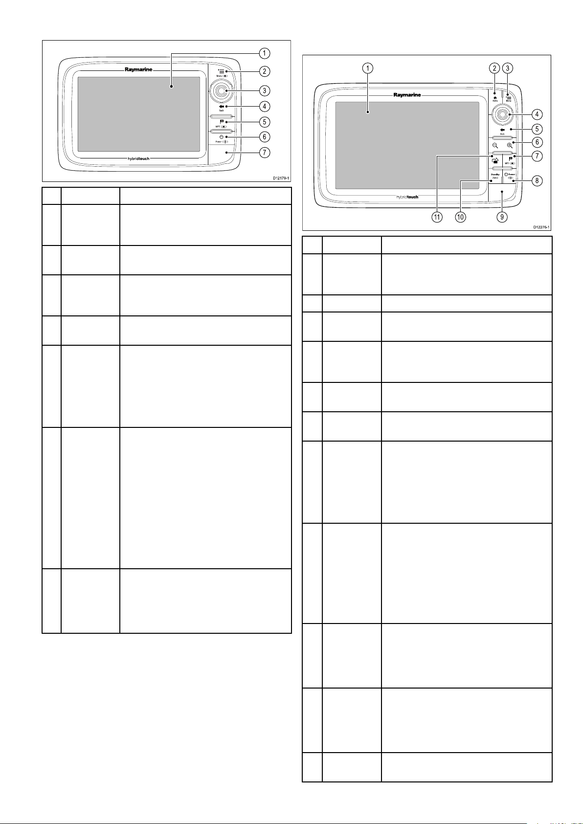
6.3e7/e7DControls
D1217 9-1
2
4
5
6
7
3
1
D1227 6-1
1
2 3
4
5
6
7
11 10
8
9
6.4c95/c97/c125/c127/e95/e97/
e125/e127/e165Controls
DescriptionFunctions
1Touch-
screen
youcantouchthescreentooperatemany
commonfunctions,includingallmenu
operations.
2MenuAccessesmenus.Pressagaintoclose
menus.
3
UniControl
Providesajoystick,rotarycontroland
anOKpushbuttonforusingmenusand
applications.
4BackPresstoreturntoapreviousmenuor
dialoglevel.
5
WPT/MOB
•Pressandreleasetoaccessthe
waypointoptions.Pressagaintoplace
awaypoint.
•PressandholdtoplaceaMan
Overboard(MOB)markeratyour
currentposition.
6Power
•PressoncetoswitchtheunitON.
•Oncepoweredon,pressthePower
buttonagaintoadjustthebrightness,
performascreencapture,access
Powersavemodeoraccessthepower
controlsforexternaldevices.
•PressandholdtoswitchtheunitOFF .
•Ifanintegratedpilotisengaged,
pressandholdputtheautopilotinto
STANDBYmode.
7
Cardreader
slot
Openthecarddoortoinsertorremove
aMicroSDcard.Thereare2cardslots
(labelled1and2),usedforelectronic
chartsandarchivingwaypoint,route,
trackandsettingsdata.
Gettingstarted
DescriptionFunctions
1Touch-
screen
youcantouchthescreentooperate
manycommonfunctions,includingall
menuoperations.
2HomePresstoreturntothehomescreen.
3MenuAccessesmenus.Pressagaintoclose
menus.
4
UniControl
Providesajoystick,rotarycontroland
anOKpushbuttonforusingmenusand
applications.
5
BackPresstoreturntoapreviousmenuor
dialoglevel.
6Range
In/Out
7
WPT/MOB
Pressminus(-)torangeoutandplus(+)
torangein
•Pressandreleasetoaccessthe
waypointoptions.Pressagaintoplace
awaypoint.
•PressandholdtoplaceaMan
Overboard(MOB)markeratyour
currentposition.
8Power
•PressoncetoswitchtheunitON.
•Oncepoweredon,pressthePower
buttonagaintoadjustthebrightness,
performascreencapture,access
Powersavemodeoraccessthepower
controlsforexternaldevices.
•PressandholdtoswitchtheunitOFF .
9
Cardreader
slot
Openthecarddoortoinsertorremove
aMicroSDcard.Thereare2cardslots
(labelled1and2),usedforelectronic
chartsandarchivingwaypoint,route,
trackandsettingsdata.
10Pilot•Presstodisengageintegrated
autopilot.
•PressandholdtoactivateAutomode
onintegratedautopilot.
11
Switch
ActivePane
Presstoswitchtheactivepane(in
splitscreenpages).
91

UniControl
D1218 0-1
1
2
3
D7366_3
D7368_2
D7369-2
WPT
Usingthecursor
Non-touch,HybridT ouchandtheremotekeypad
includeaUniControlwhichconsistsofRotary,
Joystickandapushbuttoncontrol.
Thecursorisusedtomovearoundthescreen.
Thecursorappearsonthescreenasawhite
cross.
Ifthecursorhasnotbeenmovedforashort
periodoftime,itchangestoacirclewithacross
init,tomakeiteasiertolocateonthescreen.
Thecursoriscontext-sensitive.Whenitis
placedoveranobjectsuchasawaypointor
chartfeature,itchangescolorandalabel
orinformationassociatedwiththeobjectis
displayed.
Listofcursorlabels
LabelFeatureApplication
A/B
Rulerline
AISAIStargetChart
COGCourseOver
Groundvector
Chart
Chart
1.Rotary—usethistoselectmenuitems,move
theon-screencursor,andadjusttherangeinthe
chartandradarapplications.
2.Joystick—usethistomovethecursorposition
inapplications,panup,down,leftandrightinthe
chart,weatherandshnderapplicationsorto
cyclethroughdatapagesinthedataapplication.
3.OKbutton—pushtheendofthejoystickto
conrmaselectionorentry .
Touchicons
Touchscreenmultifunctiondisplayscanuse
theBACKandCLOSEiconstomovebetween
thedifferentlevelsofmenusavailableineach
application.
Back—gobackonelevel(sameeffectaspressing
theBACKbutton).
CTRCenterofradar
FLT
FloatingEBL/VRM
GRDGuardzone
HDG
Headingvector
MARPAMARPAtargetRadar
MOBManOverBoard
marker
POS
Vessel'sposition
RTERouteleg
SHMShip'sHeading
Marker
TIDETideindicator
TRACK
VRM/EBL
Trackline
VRMandEBL,1
or2
WINDWindindicator
WPTWaypoint
Radar
Radar
Radar
Chart
Chart,Radar
Chart
Chart
Radar
Chart
Chart
Radar
Chart
Chart,Radar
Close—closeallopenmenus(sameeffectas
pressingtheMENUbutton).
92aSeries/cSeries/eSeries
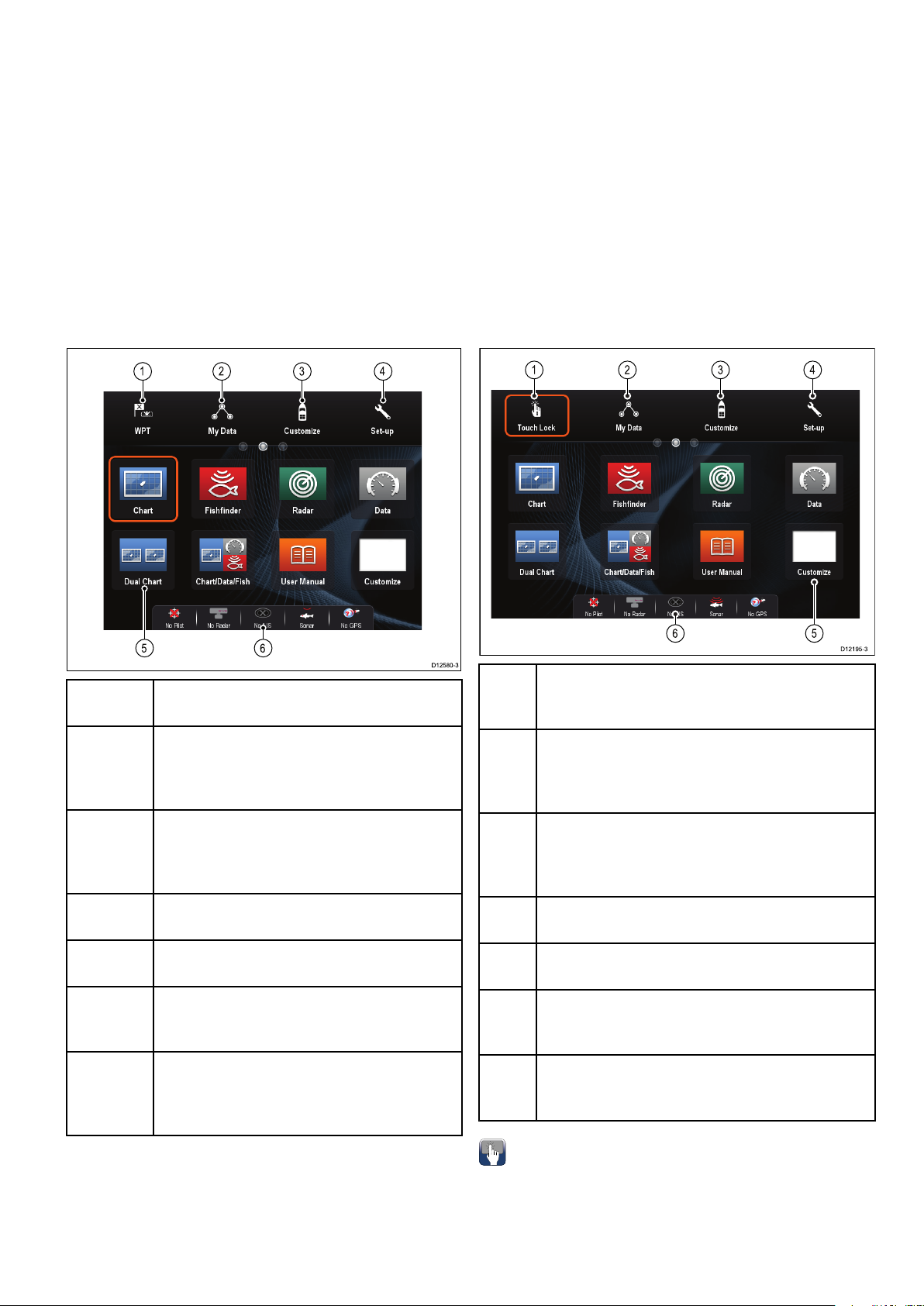
6.5Homescreenoverview—Touch
D12580-3
1 2
3
4
5 6
1 2 3 4
6 5
onlydisplays
6.6Homescreenoverview—cSeries/ eSeries
TheHomescreenprovidesacentralpointofaccess
foryourdisplay'sapplications,dataandsettings.
•TheHomescreenprovidesquickaccesstoyour
data(waypoints,routes,tracks,imagesand
videos)andbackupsettings.
•TheHomescreenconsistsofanumberof
Homescreenpages.Swipethescreenleftorright
withyourngertoscrollthroughtheavailable
Homescreenpages.
•EachHomescreenpageconsistsofanumberof
icons.Applicationsarestartedbyselectingthe
relevanticon.
Screen
itemDescription
1Waypoint—selecttheicontoaccessthe
waypointlist.Selectandholdontheiconto
placeaManOverboard(MOB)markeratyour
vessel’scurrentposition.
2MyData—thisiconenablesyoutocentrally
manageyourdataincludingroute,track,and
waypointlists.Youcanalsoaccesssaved
picturesandvideosandbackupsettings.
3
Customize—selectthisicontocongure
applicationpagesanddisplaypreferences.
4
Set-up—selectthisicontoaccessthesystem
set-upmenus.
5
Icon—eachiconrepresentsanapplication
page.Apagecandisplaymultipleapplications
simultaneously.
6
Statusbar—thestatusiconsconrmthe
statusofexternally-connectedequipment,
includingGPS,AIS,radar,sonarandautopilot
units.
Screen
itemDescription
1
TouchLock—(HybridT ouchdisplaysonly)select
thisicontolockthetouchscreen,preventing
accidentaluse.T ounlock,usetheUniControlto
deselecttheT ouchLockicon.
2MyData—thisiconenablesyoutocentrally
manageyourdataincludingroute,track,and
waypointlists.Y oucanalsoaccesssavedpictures
andvideosandbackupsettings.
3
Customize—selectthisicontocongure
applicationpagesanddisplaypreferences.
4
Set-up—selectthisicontoaccessthesystem
set-upmenus.
5
Icon—eachiconrepresentsanapplication
page.Apagecandisplaymultipleapplications
simultaneously.
6
Statusbar—thestatusiconsconrmthestatus
ofexternally-connectedequipment,includingGPS,
AIS,radar,sonarandautopilotunits.
Gettingstarted
Accessingthehomescreen
Thehomescreencanbeaccessedfromany
application.
Toaccessthehomescreenfollowthestepsbelow:
1.Selectthehomescreeniconon-screen.
93
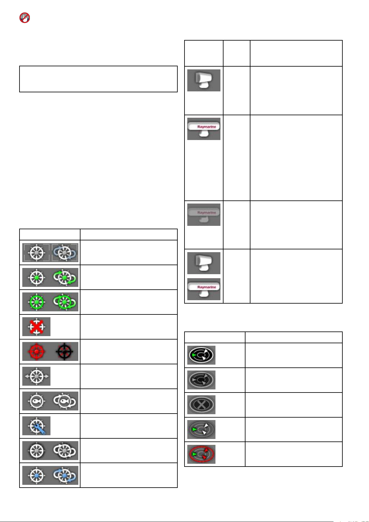
Accessingthehomescreen
Thehomescreencanbeaccessedfromany
application.
Toaccessthehomescreenfollowthestepsbelow:
1.PresstheHomebutton.
Radarscannerstatussymbols
Theradarscannerpowermodestatusisindicated
inthedatabar.
Radar
power
Symbol
modeDescription
Note:Thee7ande7DhaveacombinedMenu
andHomebutton,toaccessthehomescreenpress
andholdtheMenu/Homebuttonfor3seconds.
Databarstatussymbols
Thestatussymbolsonthedatabarconrmwhether
theappropriateconnectionstoyoursystemhave
beenmade.
Thesymbolsshowthestatusforthefollowing:
•Radarscanner.
•AISreceiver/transceiver.
•Sonarmodule.
•GPSreceiver.
•Autopilot.
Autopilotstatussymbols
Theautopilotstatusisindicatedinthedatabar.
SymbolDescription
AutopilotisinStandbymode.
AutopilotisinTrackmode.
Transmit(TX)
Rotatingicon,signifyingthatthe
scannerisonandtransmitting.
WhenSCANNERissettoON,
selectthismodetoactivatethe
scanner.Thisistheusualmodeof
operation.
Standby
(STBY)
Staticicon,indicatingthatthe
scannerisonbutnottransmitting,
andtheantennaisnotrotating.
Thescannerdoesnottransmitand
theradardataisremovedfromthe
screen.Thisisapower-savemode
usedwhentheradarisnotneeded
forshorttimeperiods.When
youreturntotransmitmode,the
magnetrondoesnotneedtowarm
upagain.Thisisthedefaultmode.
OffScannerpoweredoffwhenradar
notrequired,butdisplayisinuse
forotherapplications,suchasthe
chart.Whenselected,thesystem
countsdown.Duringthistimeyou
cannotre-powerthescanner.
Timed
Transmit
Scannerswitchesbetween
on/transmitting,andstandbymode.
Scannergoesintopowersave
modewhenconstantuseofradar
isnotrequired.
AutopilotisinAutomode.
Noautopilotdetected.
Autopilotalarmactive.
Dodgemodeisactive.
Fishmodeisactive.
Autopilotcalibration.
Powersteeringactive.
WindVanemodeisactive.
AISstatussymbols
AISstatusisindicatedbyasymbolinthedatabar.
SymbolDescription
AISunitisswitchedonandoperating.
AIScurrentlyunavailable.
AISunitisswitchedoff,ornot
connected.
AISunitisinSilentMode.
AISunitisinSilentMode,withactive
alarms.
94aSeries/cSeries/eSeries
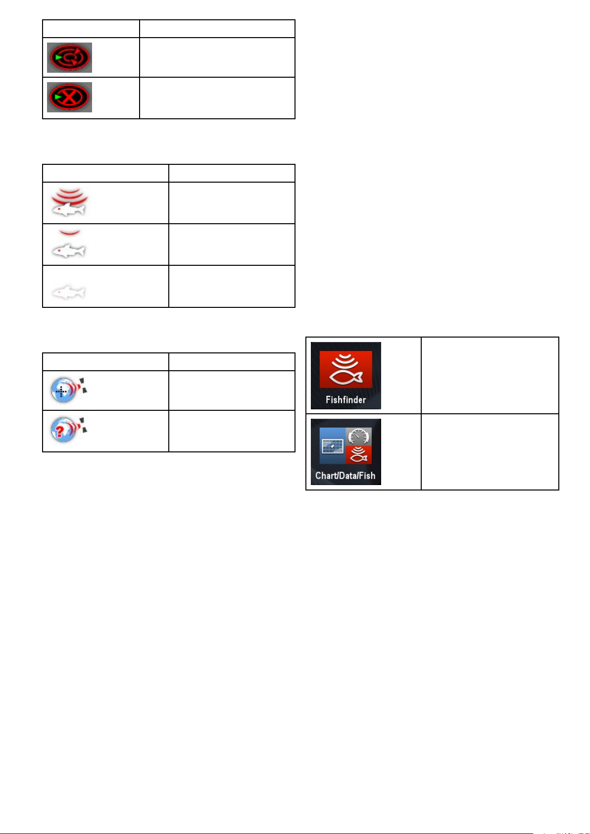
SymbolDescription
6.7Pages
AISunitisconnectedandswitched
on,buthasactivealarms.
AISunitisconnectedandswitched
on,butthedangerousandlostalarm
isdisabled.
Sonarstatussymbols
Thesonarstatusisindicatedinthedatabar.
SymbolDescription
Symbolanimated:thesonar
moduleisconnectedand
transmitting.
Symbolstatic:thesonar
moduleisconnectedbutnot
transmitting.
Symbolgreyed-out:thesonar
moduleisnotconnected,or
isnotdetected.
GPSstatussymbols
TheGPSreceiverstatusisindicatedinthedatabar.
SymbolDescription
Pagesaremadeupof1to4panesthatareused
todisplayapplicationsonyourmultifunctiondisplay
(MFD).
Pagesareaccessedusingtheiconsonthe
Homescreen.
•Youcancreateupto2applicationpanesperpage
usinganMFDthathasascreensizeof7inches
orless.
•Youcancreateupto4applicationpanesperpage
usinganMFDthathasascreensizeofgreater
than7inches.
•MFDswithascreensizeof7inchesorlesscan
viewpageswithmorethan2applicationpanes
butonlyiftheyaresharingtheHomescreenofan
MFDwhichiscapableofcreatingthosepages.
Pagescanbecustomized,enablingyoutogroup
yourapplicationsintodifferentpages,eachdesigned
foraspecicpurpose.Forexample,youcould
haveapagethatincludesthechartandshnder
applications,suitableforshing,andanotherpage
thatincludesthechartanddataapplications,which
wouldbesuitableforgeneralsailing.
Iconforapagefeaturingasingle
application.
AGPSreceiverisconnected
andhasobtainedax.
AGPSreceiverisnot
connected,orcannotobtain
ax.
Iconforapagefeaturingmultiple
applications.
Youcanalsodenethelayoutforeachpage,which
determineshowtheapplicationsarearrangedon
thescreen.
SettingthePower-uppage
Youcansetupyourmultifunctiondisplaytoshowa
pageinsteadoftheHomescreenatpowerup.
FormtheHomescreen:
1.SelectCustomize.
2.SelectDisplayPreferences.
3.SelectStartingpage.
Alistofoptionsisdisplayed
•Homescreen—Homescreenisdisplayedafter
power-up.
•Lastpage—Thepagelastviewedisdisplayed
afterpower-up
•Choosepage—Thepageyouselectwillbe
displayedafterpower-up
Gettingstarted
95

4.IfselectingChoosepagetheHomescreenis
displayed.
5.Selecttheiconforthepageyouwantdisplayed
whenthedisplayisturnedon.
Thestartingpagesettingappliestoeachindividual
displayandisnotautomaticallysharedonnetworked
displays.
2.SelectHomescreen.
3.SelectSwapPage.
4.Selectthepageiconthatyouwanttomove.
5.Selectthepageiconthatyouwanttoswap
positionswith.
Thepageiconismovedtothenewposition.
Renamingapageonthehomescreen
Withthehomescreendisplayed:
1.SelecttheCustomizeicon.
2.SelectHomescreen.
3.SelectRenamePage.
4.Selectthepagethatyouwanttorename.
Theon-screenkeyboardisdisplayed.
5.Usingtheon-screenkeyboard,enterthenew
nameforthepage.
6.SelectSA VE.
Changinganexistingpageonthe
homescreen
Withthehomescreendisplayed:
1.SelectCustomize.
2.SelectHomescreen.
3.SelectEditPage.
4.Selectthepageiconthatyouwanttochange.
TheCustomizemenuoptionsaredisplayed.
5.Selecttheappropriatepagelayout(forexample,
“Splitscreen”).
6.Selecttheapplication(s)youwanttodisplayon
thepage,eitherbyselectingtherelevantmenu
itemordraggingitovertothedisplayedpage.
7.SelectFinish.
TheRenamePagedialogisdisplayed.
8.Usetheon-screenkeyboardtonamethepage,
thenselectSave.
Changinganemptypage
Withthehomescreendisplayed:
1.SelectCustomize.
2.SelectHomescreen.
3.SelectEditPage.
4.Selectanemptypageicon(labelled“Customize”).
TheCustomizemenuoptionsaredisplayed.
5.Selecttheappropriatepagelayout(forexample,
“Splitscreen”).
6.Selecttheapplication(s)youwanttodisplayon
thepage,eitherbyselectingtherelevantmenu
itemordraggingitovertothedisplayedpage.
7.SelectFinish.
TheRenamePagedialogisdisplayed.
8.Usetheon-screenkeyboardtonamethepage,
thenselectSave.
Deletingapagefromthehomescreen
Withthehomescreendisplayed:
1.SelecttheCustomizeicon.
2.SelectHomescreen.
3.SelectDeletePage.
4.Selectthepagethatyouwanttodelete.
Thepageisdeleted.
Resettingthehomescreentodefaultsettings
Withthehomescreendisplayed:
1.SelecttheCustomizeicon.
2.SelectHomescreen.
3.SelectReset.
Awarningmessageisdisplayedaskingfor
conrmation.
4.SelectYestoresetthehomescreentothedefault
rangeofpages,orNotocanceltheoperation.
Movingapageonthehomescreen
Withthehomescreendisplayed:
1.SelecttheCustomizeicon.
96aSeries/cSeries/eSeries

6.8Applications
FUSIONLinkapplication—link
toandcontrolacompatibleFusion
Chartapplication—providesa2Dor
3Dgraphicalviewofyourchartstohelp
entertainmentsystemfromyour
multifunctiondisplay.
younavigate.Waypoint,route,and
trackfunctionsenableyoutonavigate
toaspeciclocation,buildandnavigate
routes,orrecordwhereyou'vebeen.
Chartcardsprovidehigherlevelsof
SiriusAudioapplication—control
Siriusradiofromyourmultifunction
display.
detailand3Dviews.
Fishnderapplication—with
atransducerandasonarvariant
multifunctiondisplayorcompatible
SonarModule,youcanusethe
shnderapplicationtohelpyou
accuratelydistinguishbetweendifferent
sizesofsh,bottomstructure,and
underwaterobstacles.Youcanalso
viewseadepthandtemperaturedata
andmarkpointsofinterestsuchas
shingspotsorwrecks.
Radarapplication—withasuitable
radarscanner,youcanusethe
radarapplicationtotracktargetsand
measuredistancesandbearings.A
numberofautomaticgainpresetsand
colormodesareprovidedtohelpyou
getthebestperformancefromyour
radarscanner.
Dataapplication—viewsystemand
instrumentdataonyourmultifunction
display,forarangeofcompatible
instruments.Usethejoystickor
touchscreentoscrollthroughthe
availabledatapages.
UserManual—OpenstheEnglish
versionoftheproductusermanual
storedonthedisplay.Toopen
translatedusermanualsstoredon
memorycardusetheDocViewer.
Weatherapplication—(North
Americaonly).Withasuitableweather
receiverconnectedtoyoursystem,the
weatherapplicationoverlayshistorical,
live,andforecastedweathergraphics
onaworldmap.
Thermalcamapplication—view
andcontrolathermalcamerausinga
compatiblemultifunctiondisplay.
Note:Thethermalcamera
applicationisnotavailableona6x
anda7xvariantMFDs.
Cameraapplication—viewavideo
orcamerasourceonyourmultifunction
display.
DocViewer—viewpdfdocuments
storedonaMicroSDcard.
Gettingstarted
97

6.9Splitscreencontrols
D12880-1
2 3
4
1
5
Whenviewingapagewithmorethan1application
displayedyoucanswitchapplicationsfromthe
splitscreenviewtofullscreenview.
Example1—Splitscreenpage
Example2—Fishnderapplicationexpanded
toFullscreen
3.UsetheRangeinorRangeoutcontrolsto
switchtheactiveapplicationbetweensplitscreen
andfullscreenviews.
Selectingtheactivewindow—e7/e7D
Whenviewingasplitscreenpageyoucanselectthe
activeapplicationandviewitfullscreenonane7/
e7Dwiththetouchlockenabledbyfollowingthe
stepsbelow.
Withapagefeaturingmultipleapplicationsdisplayed:
1.PresstheMenubutton.
2.SelectCycleapplication.
Selectingcycleapplicationcyclesthroughthe
availableapplications.
3.SelectFullscreentoviewtheactiveapplication
infullscreen,or
4.SelectSplitscreentoreturntothesplitscreen
view.
Switchingtheactivepaneordisplayusing
thekeypad
Selectingtheactivewindow
Whenviewingasplitscreenpageyoucanselectthe
activeapplicationandviewitfullscreenbyfollowing
thestepsbelow.
Withapagefeaturingmultipleapplicationsdisplayed:
1.T ouchanywhereinsidetheapplicationyouwant
tomakeactive.
Aborderappearsaroundtheapplication,
indicatingthatitisactive.
2.SelectMenu.
3.SelectFullscreentoviewtheactiveapplication
infullscreen,or
4.SelectSplitscreentoreturntothesplitscreen
view.
Selectingtheactivewindowusing
Non-touchcontrols
Whenviewingasplitscreenpageyoucanselectthe
activeapplicationandviewitfullscreenusingthe
MFD’sphysicalbuttonsoraremotekeypad.
Withapagefeaturingmultipleapplicationsdisplayed:
TheSwitchActivebuttonisusedtoswitchtheactive
paneonamultiapplicationpageand/ortoswitch
theactivedisplay.
Withmultipledisplaysconnectedand/ormultiple
applicationpage(s)displayed:
Cyclesequence
1.PresstheSwitchActivebuttontoenterswitch
mode.
2.UsetheRotarycontroltocyclethroughthe
availablepanesand/ordisplays.
Thekeypadwillcyclethroughdisplaysinthe
orderinwhichtheywerepaired.Onmulti
applicationpagestheRangebuttonscanbeused
toswitchtheactiveapplicationbetweenfulland
splitscreen.
3.PresstheBackbuttonortheSwitchActive
buttontoexitswitchmode.
1.Pressthe
SwitchActivebutton.
Theactivepanepopupisdisplayed:
2.PresstheSwitchActivePanebuttonorusethe
Rotarycontroltocycletheactiveapplication.
98aSeries/cSeries/eSeries

6.10Screenoverview
7
6
1
2 3
4
5
D12281- 4
3
4
5
1 2
D12277-2
1 4
5
2 3
ScreenitemDescription
1Home
•Displayswithatouchscreen—Select
theonscreenHomeicontoaccessthe
Homescreen.
•Non-touchscreenandHybridTouch
displays—UsethephysicalHomebutton
toaccesstheHomescreen.
2
Databar—providesinformationaboutyour
vesselanditsenvironment.Thetypeof
informationinthedatabarcanbecustomized
fromtheHomescreen>Customize>
DatabarSet-upmenu,ifrequired.
3
Menu—menuoptionsarespecictothe
applicationthatyouarecurrentlyusing.
4
Statusbar—providesinformationspecic
toeachapplication.Thisinformationcannot
beeditedormoved.
5
Contextmenu—providesinformationand
optionsspecictoeachapplication.
6Menuoptions—menuoptionsaredisplayed
whentheMenuisselected.
7
Pop-upmessages—alertyoutoasituation
(suchasanalarm),orunavailablefunction.
Pop-upmessagesmayrequirearesponse
fromyou—forexample,selectOKtosilence
alarms.
Menus
Screen
itemDescription
1
Back—Ondisplayswithatouchscreenyoucan
presstheonscreen<<(back)icontogobackto
apreviousmenu.Onnon-touchscreendisplays
orHybridTouchdisplaysusetheBackbutton.
2
Close—Ondisplayswithatouchscreenyou
canpresstheonscreenX(close)icontogo
backtoapreviousmenu.Onnon-touchscreen
displaysorHybridTouchdisplaysusetheBack
buttontobackoutofthemenustructure.
3
Selectedmenuoption—themenuoption
currentlyselectedwillbehighlighted.
4
Scrollbar—indicatesthatfurthermenu
itemsareavailablebyscrollingthemenu.On
displayswithatouchscreentoscrollthrough
theavailablemenuitems,pressandholdyour
ngeronthemenuanddragitupordown.
Onnon-touchscreendisplaysorHybridTouch
displaysusetheRotarycontrol.
5
On/Offswitch—Ondisplayswitha
touchscreenyoucanselectonscreenmenu
itemstoswitchfeaturesOnorOfftoenable
ordisablethefunction.Onnon-touchscreen
displaysorHybridT ouchdisplaysusetheOK
buttontoswitchthefunctionOnorOff.
Dialogs
Dialogsarefullscreenmenusthatenableyouto
managedataitemssuchaswaypointsandroutes.
Menusenableyouconguresettingsand
preferences.
Menusareusedinthe:
•Homescreen—tocongureyourmultifunction
displayandexternally-connectedequipment.
•Applications—tocongurethesettingsforthat
particularapplication.
Gettingstarted
99
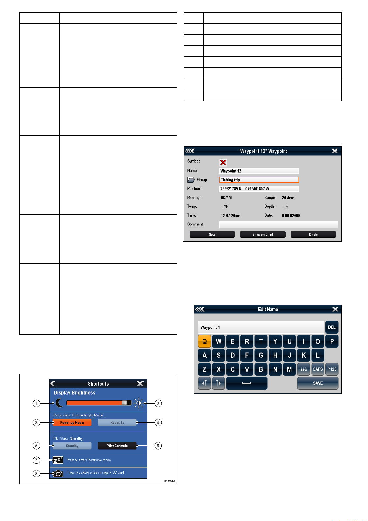
ScreenitemDescription
D13004-1
1
3
5
7
8
4
2
6
1Decreasedisplaybrightness
1Back
2
3
•Displayswithatouchscreen—Selectthe
onscreenBackicontogobacktothe
previousmenu.
•Non–touchscreenorHybridTouchdisplays
—UsetheBackbuttontogobacktothe
previousmenu.
Functionicons—Somedialogsinclude
iconswhichcanbeselectedtoaccess
additionalfunctions.Forexample,inthe
WaypointListdialog,theSortbyiconcan
beusedtochangehowthewaypointslistis
sorted.
Menu/Listitem
•Displayswithatouchscreen—
Momentarilytouchinganitemautomatically
selectstheitemanddisplaystheitem
optionsmenu.
•Non–touchscreenorHybridTouchdisplays
—UsetheRotarycontroltohighlightan
item,andtheOkbuttontoselectitand
displaytheitemoptionsmenu.
2Increasedisplaybrightness
3
4
5
Powerup/PowerdownRadar
Radarstandby/Radartransmit
Autopilotstandby(duringactivenavigation)
6Displaypilotcontroldialog
7
8
PowerSavemode
Screenshot/Screencapture
Editdialogs
Editdialogsenableyoutoeditthedetailsofdata
itemsstoredonyourmultifunctiondisplay,suchas
waypoints,routes,andtracks.
4
Close
•Displayswithatouchscreen—Selectthe
onscreenCloseicontoclosethedialog.
•Non–touchscreenorHybridTouchdisplays
—UsetheBackbuttontoclosethedialog.
5
Scrollbar
•Displayswithatouchscreen—Toscroll
throughtheavailableitems,pressand
holdyourngeronthescrollbaranddrag
itupordown.
•Non–touchscreenorHybridTouchdisplays
—T oscrollthroughtheavailablemenu
items,usetheRotarycontrol.
Shortcutspage
Anumberofusefulfunctionscanbeaccessedfrom
theShortcutspage.
Selectingatextelddisplaystheonscreenkeyboard,
whichcanbeusedtoeditthedetails.
Editinginformationindialogs
Withthedialogdisplayed:
1.Selecttheeldyouwanttoedit.
Theonscreenkeyboardisdisplayed:
2.Usetheonscreenkeyboardtomakethechanges.
3.SelectSAVEtosavethechanges.
Enteringspecialoraccentedcharacters
Withtheonscreenkeyboarddisplayed:
1.Selecttheonscreenkeyboard'sàèòkey.
2.Selectthecharacteryouwanttoaccent.
Theavailableaccentedcharactersaredisplayed
abovethetextentryeld.
100aSeries/cSeries/eSeries
3.Forcharactersthathavemultipleavailable
accents,usethecharacterkeytotogglebetween
them.
4.Selecttheàèòkeytoenterthecharacter.
 Loading...