

Page 1
TM
WARRANTY TERMS AND CONDITIONS
AUSTRALIA
LIGHTFORCE AUSTRALIA warrants to the PURCHASER that this product shall be free from defects in design, materials and workmanship, except as otherwise set forth herein, for a
period of 1 year from the date of purchase. The onus of proof of the date of purchase shall lie upon the PURCHASER and if the PURCHASER cannot establish the purchase date by
the appropriate documentary evidence, the purchase will be deemed to have taken place in excess of 1 year from the date upon which the defect occurred. The sole obligation of
LIGHTFORCE AUSTRALIA shall be the repair or (at the absolute option of LIGHTFORCE AUSTRALIA) the replacement of the defective product or part. LIGHTFORCE AUSTRALIA shall
have no other liability to the PURCHASER for any consequential loss including but not limited to loss of income, compensation for personal injury, or injury to property.
INTERNATIONAL
Please consult place of purchase. PLEASE NOTE globes and batteries are not covered by warranty. A dated receipt of proof of purchase must be provided.
All warranties express or implied of merchantability, fitness for a particular purpose and other warranties of whatever kind are, to the extent permitted by law, hereby disclaimed.
Claims under this warranty must be made in writing addressed to LIGHTFORCE AUSTRALIA Pty. Ltd., shall be not be liable for damage, malfunction, failure resulting from accident,
misuse, misapplication, unauthorised repair, neglect, modification, unauthorised or non standard replacement parts, accessories, globes, batteries or voltage or the operation of the
Product beyond its technical and environmental specifications.
The PURCHASER acknowledges that local laws may prohibit the use of some of the Product on motor vehicles travelling on public roads and agrees that it is his/her responsibility to
ascertain the effect of local laws.
This warranty shall be only be carried or added to in writing by LIGHTFORCE AUSTRALIA Pty. Ltd., signed by its manager. No dealer or agent or representative of LIGHTFORCE
Product has any authority to bind LIGHTFORCE AUSTRALIA Pty. Ltd. to any agreement or representation.
LIGHTFORCE AUSTRALIA
28 Orsmond Street
Hindmarsh SA 5007
Australia
Tel: 08 8440 0888
Fax: 08 8346 0504
lightforce.com
[email protected]
Int’l Tel: +61 8 8440 0888
Int’l Fax: +61 8 8346 0504
Head Office:
Genesis HID UPGRADE KIT
50 watt
USER INSTRUCTIONS
100
95
75
25
5
0
Page 2
User Instructions
SAFETY NOTES
DO NOT CUT ANY PART OF THE BALLAST OR BULB CABLES
DO NOT USE ADDITIONAL CABLES BETWEEN THE BALLAST AND THE BULB
ALWAYS DISCONNECT POWER BEFORE DISASSEMBLY OF LIGHT
ALWAYS WEAR SAFETY GLASSES WHEN HANDLING ANY BULB
DO NOT HANDLE THE GLASS SECTION OF BULB
Handle the base of bulb only, if glass gets dirty then clean with Isopropyl Alcohol or Methylated Spirits.
READ ALL INSTRUCTIONS BEFORE COMMENCING INSTALLATION
Box Contents
Tools Required
INSTRUCTION DATA
PRODUCT: XGT HID UPGRADE
VER: 1.0
DATE: APRIL 2013
50w HID Ballast x2 Globe assembly retainer x2
50w HB3 Bulb x2
Ballast retaining bracket x2
PK Screws (PH1) x2
Red dress ring x2
1
6
FIG. 7
Connect HID globe/holder to shroud
FIG. 8
100
95
75
25
5
0
Page 3
Installation
1. Remove light from its mounting position and place on a flat surface, the filter can
remain fitted to the light.
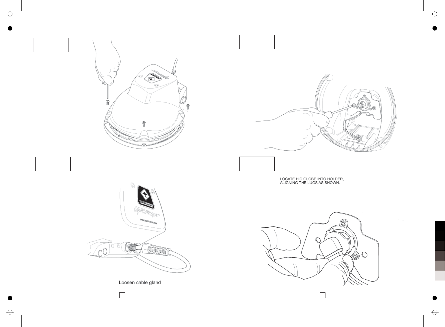
2. Remove the 4 (4mm) allen set screws. (Fig:1)
3. Separate the reflector from the housing and put aside.
4. Remove the existing bulb by gently pulling out with a side to side motion avoid
twisting as this will result in the glass base splintering.
5. Disconnect the two wires connected to the bulb holder. (Fig:3)
6. Remove the two Phillips (PH2) self tapping screw from the bulb retainer, note the
screws will be reused the bulb retainer will not. (Fig:3)
The housing is now ready to be fitted with the new components.
7. Remove the HID bulb from its protective cover along with the clear plastic disc
located at the base of the bulb and fit into the new bulb retainer, locating the
lugs as shown. (Fig:4)
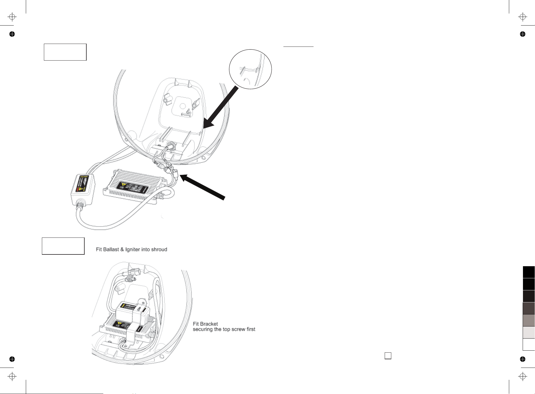
8. Fit the new ballast connecting its Red wire to the Blue wire retained in the
housing and its Black wire to the Brown wire. If you have loosened the cable
gland (Fig: 2) extra wire can be pulled through for ease of fitment.
9. Fit the ballast into the housing ensuring all cables are located to the right hand
side.
10. Ensure the ballast sits on top of the locating lug at the back of the housing
(Fig:5A) otherwise the bracket will not locate correctly.
11. Fit the retaining bracket as shown (Fig:6) securing the top screw first then the
bottom screw.
12. Connect the HID bulb to the ballast cables by connecting the two corresponding
single AMP connections until they lock into place, and then fit the new globe
assembly retainer ensuring all cables are fitted behind the retainer.
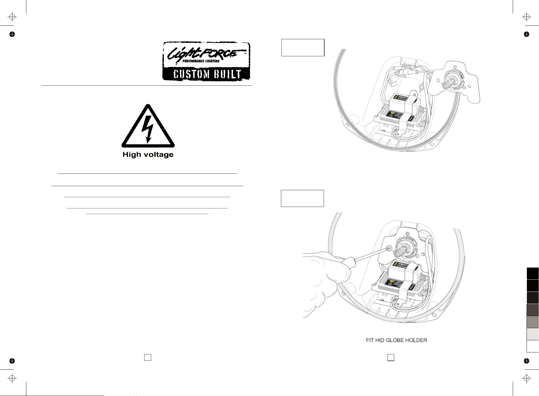
13. Ensure the retainer is located correctly on the two supporting posts then refit the
two self tapping screws until firm. (Fig:8) If the retainer is not located correctly
on the two supporting posts the beam pattern will be misaligned.
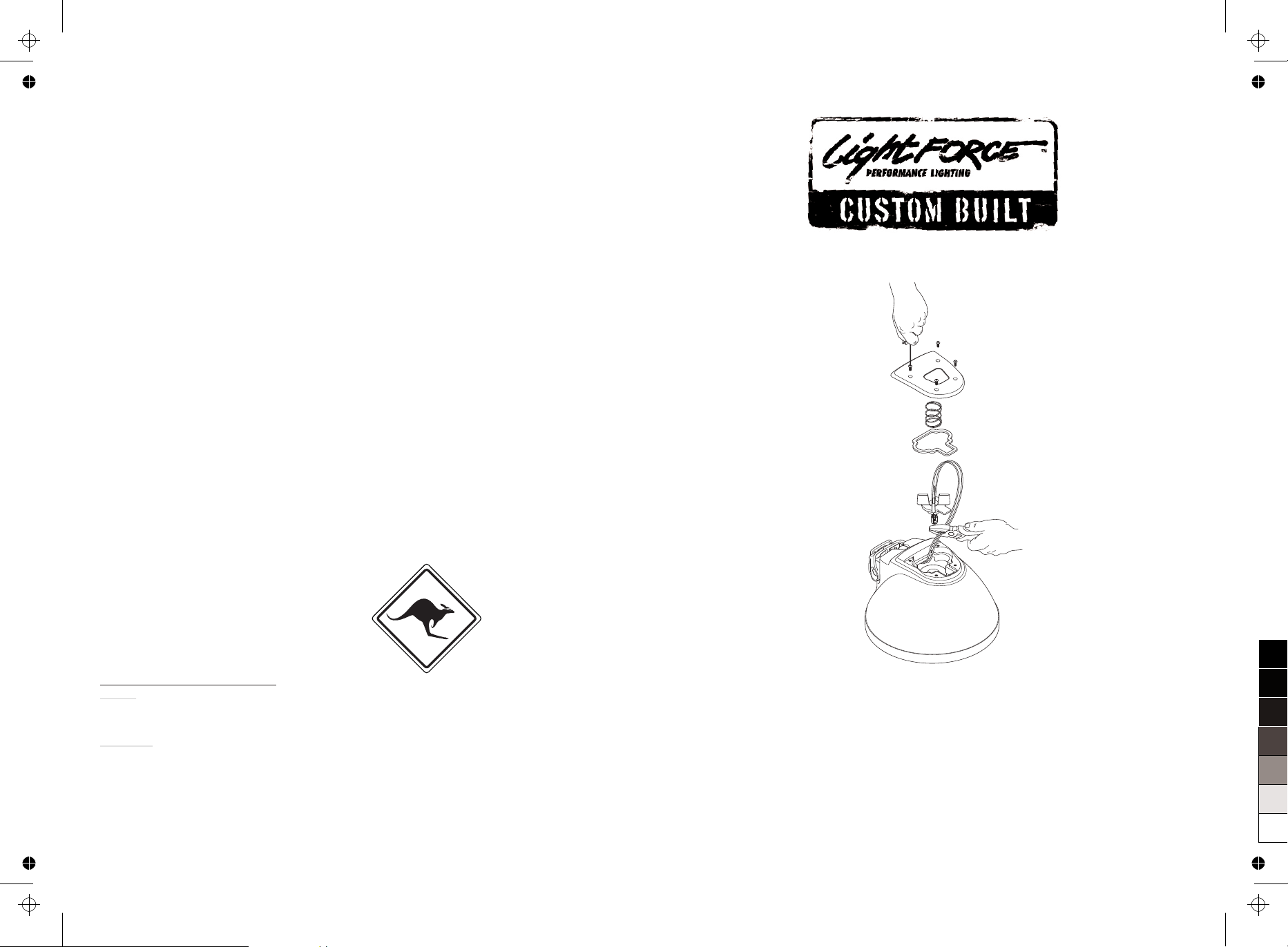
14. Position the housing facing up and fit the Red dress ring over the bulb. (Fig:8)
15. Ensuring the lens seal is still in place and undamaged.
16. Refit the bezel.
17. Turn housing over and refit the four Allen set screws evenly until firm (4Nm).
18. If you had loosened the cable gland ensure it is retightened firmly
2
5
FIG. 5FIG.
FIG. 6
Connect ballast & igniter connectors
100
95
75
25
5
0
Page 4
4
3
FIG. 1
FIG. 2
FIG. 3FIG. 3
FIG. 4
100
95
75
25
5
0
 Loading...