

Page 1
TM
Genesis Lighting System Spare Parts and Accessories
For extended accessories and spare parts please contact your local Lightforce dealer or
email [email protected]
Specifications
Recommended Operating Temperature (ambient)
0 0
40 C (104 F) MAXIMUM
WARRANTY TERMS AND CONDITIONS
AUSTRALIA
LIGHTFORCE AUSTRALIA warrants to the PURCHASER that this product shall be free from defects in design, materials and workmanship, except as otherwise set forth herein, for a
period of 3 years from the date of purchase. The onus of proof of the date of purchase shall lie upon the PURCHASER and if the PURCHASER cannot establish the purchase date by
the appropriate documentary evidence, the purchase will be deemed to have taken place in excess of 3 years from the date upon which the defect occurred. The sole obligation of
LIGHTFORCE AUSTRALIA shall be the repair or (at the absolute option of LIGHTFORCE AUSTRALIA) the replacement of the defective product or part. LIGHTFORCE AUSTRALIA shall
have no other liability to the PURCHASER for any consequential loss including but not limited to loss of income, compensation for personal injury, or injury to property.
INTERNATIONAL
Please consult place of purchase. PLEASE NOTE globes and batteries are not covered by warranty. A dated receipt of proof of purchase must be provided.
All warranties express or implied of merchantability, fitness for a particular purpose and other warranties of whatever kind are, to the extent permitted by law, hereby disclaimed.
Claims under this warranty must be made in writing addressed to LIGHTFORCE AUSTRALIA Pty. Ltd., shall be not be liable for damage, malfunction, failure resulting from accident,
misuse, misapplication, unauthorised repair, neglect, modification, unauthorised or non standard replacement parts, accessories, globes, batteries or voltage or the operation of the
Product beyond its technical and environmental specifications.
The PURCHASER acknowledges that local laws may prohibit the use of some of the Product on motor vehicles travelling on public roads and agrees that it is his/her responsibility to
ascertain the effect of local laws.
DLSB210 Anti Theft Kit for cross bolt Optional Filters
ATN10MM Anti Theft Kit for mounting bolt F210C Spot Clear
MBS Modular Stay Bracket F210CC Combo Clear
F210WC Wide Clear
Replacement Bulbs F210CB Spot Crystal Blue
GL02 Halogen Bulb F210CCB Combo Crystal Blue
GL20 HID Bulb - 3200K Ion yellow F210WCB Wide Crystal Blue
GL21 HID Bulb - 4200K / 35W F210Y Spot Yellow
Gl22 HID Bulb - 5000K / 35W F210CY Combo Yellow
GL27 HID Bulb - 5000K / 50W F210WY Wide Yellow
C210BLK Black opaque (solid)
Operating Voltage (at light) Recommended Wire Size
2
Halogen 2.0mm (14AWG) MINIMUM
12V Light – 14VDC MAXIMUM
HID Mounting Fastener Torque Specifications
35W / 12V Light – 9-16VDC, M10 x 40mm Bottom mount bolt - 70Nm (50lb-ft)
12.8VDC Typ
35W / 24V Light - 21-29VDC, M10 x 110mm Cross-bolt - 40Nm (30lb-ft)
25.6VDC Typ
50W / Multi Voltage 12V-24VDC
GENESiS
MODULAR LIGHTING SYSTEM
USER INSTRUCTIONS
LIGHTFORCE AUSTRALIA
28 Orsmond Street
Hindmarsh SA 5007
Australia
Tel: 08 8440 0888
Fax: 08 8346 0504
lightforce.com
[email protected]
Int’l Tel: +61 8 8440 0888
Int’l Fax: +61 8 8346 0504
Head Office: Australian & International enquiries
100
95
75
25
5
0
Page 2
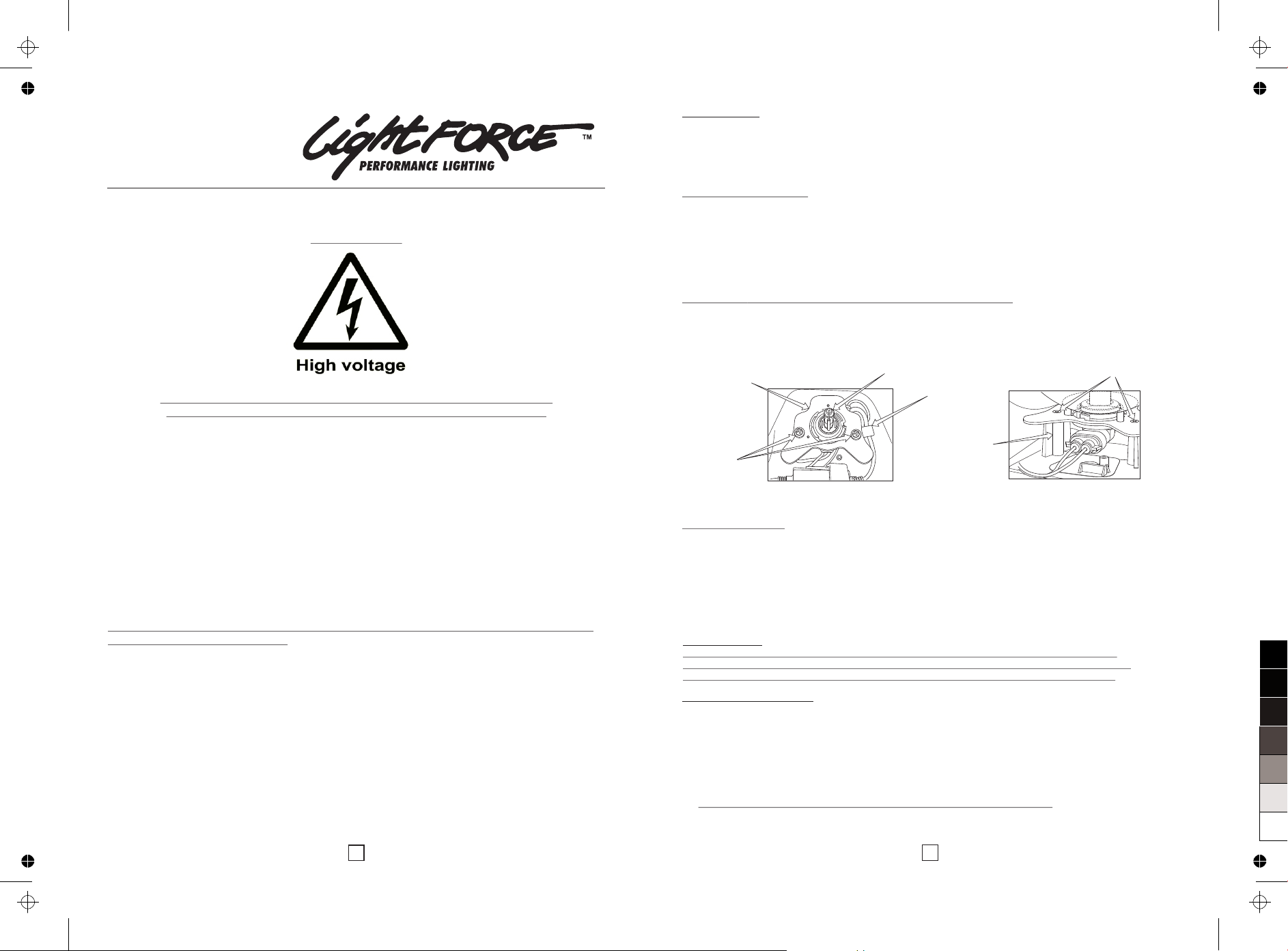
Bezel removal
HINT: When removing the bezel the filter does NOT have to be removed.
l Undo four retaining bolts. (using 4mm Allen key)
l Remove the bezel.
l Remove the lens/reflector assembly (lens and reflector will come out as one piece).
Bulb removal- Halogen
l Remove old globe by gripping firmly and pulling out in the long axis direction of the
globe
l DO NOT TOUCH NEW GLOBE WITH FINGERS, use a tissue or plastic sleeve
l Position the replacement globe legs firmly into the fixed electrodes of the globe holder,
applying firm pressure towards the rear, simply push in the new bulb. AVOID jerking
or twisting movements.
CAUTION: DO NOT HANDLE THE GLASS SECTION OF BULB
Handle the base of bulb only, if glass gets dirty then clean with Isopropyl Alcohol or
Methylated Spirits. Wear gloves and safety glasses in case of broken glass.
Bulb removal- HID
l Undo two retaining screws..
l Remove metal bracket with bulb.
l Holding the bracket bulb assembly in one hand, turn the bulb anti-clockwise until it `
stops then withdraw it..
l Remove connector(s) from bulb by lifting the lock tab and pulling apart.
Bulb and Bezel Refitting
l Refit connector(s) to bulb (ensure connector is locked in securely).
l Fit bulb to metal bracket by inserting and turning clockwise until stop is felt.
l Sit bracket/bulb assembly onto mounting posts inside the outer housing unit. Bracket
has to be fully located sitting all the way down. (Ensure harness is held down by the
bracket - HID models only).
l Fix the bracket with the two retaining screws using specified torque (see specification
section).
l IMPORTANT: Ensure lens seal is in place and undamaged.
l Refit lens/reflector and bezel to (ensure Bling Ring is placed in reflector).
6
User Instructions – Genesis Lighting Systems
SAFETY NOTES
ALWAYS DISCONNECT POWER BEFORE DISASSEMBLY OF LIGHT
ALWAYS WEAR SAFETY GLASSES WHEN HANDLING ANY BULB
READ ALL INSTRUCTIONS BEFORE COMMENCING INSTALLATION
Box Contents
General Care and Safety Tips
CAUTION: NEVER USE ANY SOLVENT BASED CLEANERS OR INDUSTRIAL DETERGENTS
WHEN CLEANING YOUR LIGHTS.
To wash your lights, use plenty of warm soapy water and a soft cloth only (this prevents
the surface from marking).
INSTRUCTION DATA
PRODUCT: GENESIS LIGHT
VER: 7.2
DATE: SEPTEMBER 2011
1 x Genesis Light
1 x Clear Filter (fitted to light) 1 x Lightforce Sticker
1 x Bottom Mount Bracket 1 x Lightforce Portable Lighting Catalogue
1 x M10 x 40mm SS Bolt 2 x M10 SS Nylock Nut
1 x M10 x 110mm SS Bolt 1 x User Instructions
2 x M10 SS Washers 1 x Loom Adapter
1
(HID MODELS)
IMPORTANT:
When removing lens/reflector do not damage or lose the rubber seal that runs around the
outside of the housing. Ensure it is fitted correctly over the housing lip to maintain sealing of
the assembly, this will avoid water/dirt ingress. Incorrect fitment of seal avoids warranty.
Metal Bracket
Retaining
screws
Globe
Harness
Metal bracket location
Housing
mounting
posts
100
95
75
25
5
0
Page 3
4
3
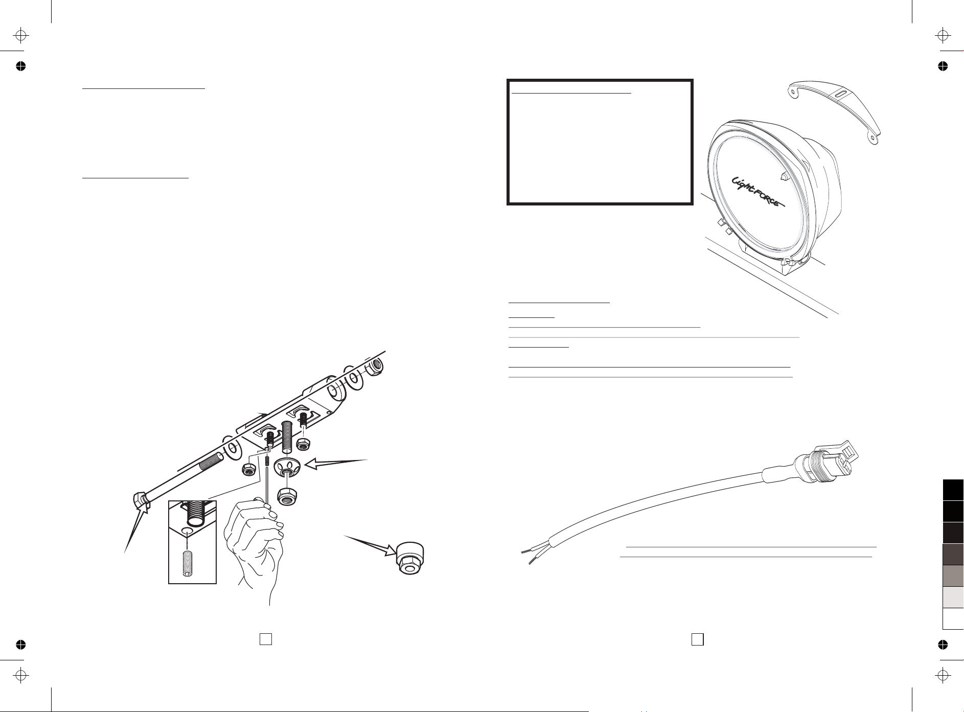
Top Mounting – Stay Bracket
Your Genesis light can be used with an
upper and/or side stay brackets for
increased mounting rigidity, to fit a stay
you will need to purchase the MBS
accessory (see your authorised Lightforce
dealer or email us at [email protected]
for more information).
Image denotes upper MBS bracket
fitted only.
Electrical Connections
Your Genesis light is fitted with a waterproof electrical connector. Included is the mating
connector fitted with a length of cable (loom adaptor) - for connection with existing wiring
harness. This connector needs to be fitted directly to your driving light loom.
CAUTION:
IMPROPER INSTALLATION OF THE TERMINALS
AND CONNECTOR WILL AFFECT THE RELIABILITY AND OPERATION OF
YOUR LIGHTS.
DO NOT REMOVE WATERPROOF CONNECTOR FROM DRIVING LIGHT
CABLE; THIS MAY LEAD TO WATER INGRESS AND VOID WARRANTY.
?HID wiring is sensitive to polarity; Genesis follows the
European automotive wiring colour coding convention:
Red wire is Positive +, when connecting to a genuine
Lightforce loom, the red wire of the loom adaptor is connected
to the white wire of the loom.
The black wire is negative -, this must be connected to the
black cable of the vehicles loom.
Anti Theft Security System
We recommend three components to provide the best protection against theft of your
lights:
1. Anti theft security bolt (optional item DL210SB)
2. Anti twist restraining bolts (not supplied) to prevent the lights from being spun
off the bull bar.
3. Anti theft nuts (optional item ATN10MM) fitted to the bottom mount bolts.
Assemble Instructions:.
1. Anti theft security bolt
l
l Assemble anti theft cross bolt, note: it can be inserted from either right or left side.
l Fasten the grub screw in line with the bolt slot using the hexagonal allen key. Note:
the grub screw self taps the thread, as it engages with the slot ensure the bolt turns
freely and is held in the bracket and cannot be removed.
l Fit Nyloc nuts and washers to the cross bolt and tighten to the specified torque.
2. Optional anti twist restraining bolts
For additional security, anti twist restraining bolts can be used to prevent your lights
from being twisted off the bull bar and also maintains the aiming position. Since each
vehicle is subtlety different, these bolts are not supplied with the kit.
3. Fit anti theft nuts
Fit the anti theft nut first followed by the Nyloc nut as per the diagram.
Assemble bottom mount bolts to bracket.
Security Nut Socket
Align slot with
grub screw
Anti Theft Nut
100
95
75
25
5
0
Page 4
Installation
Tools Needed
17mm socket on ratchet x 2
Torque wrench(s) to suit from 5Nm to 70Nm
Mounting
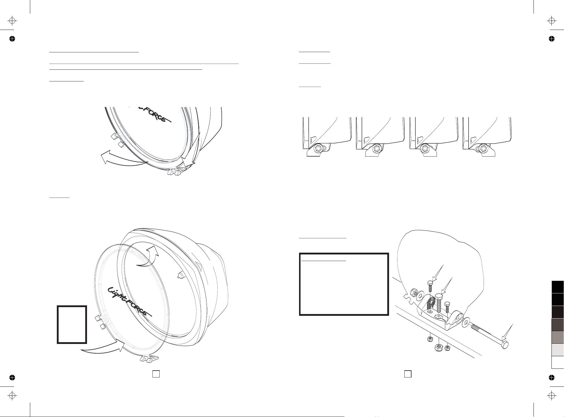
l Your Genesis light has four different mount positions (two cross-bolt holes and a
reversible mount - see picture).
l Before fitting the mount, select the most suitable position for your application.
l Insert 40mm mounting bolt into bottom mount bracket.
l Attach bottom mount bracket to light housing and insert cross-bolt using one
washer per side of mount.
l Tighten cross-bolt until firm (not tight).
l Fit light into position on light mount.
l Tighten bottom mounting bolt until firm.
l Approximately aim light (i.e. point straight ahead) then tighten both bolts as per
recommended torque specifications (see specifications section).
Mounting Options
M6 Mounting Bolts - If extra
mounting security is needed or
you have a problem with your light
rotating there are two M6
mounting holes either side of the
main M10 mounting bolt, these
will accommodate any M6 bolt
with an 11mm head size.
M6
M10
2
5
Removing and Refitting the Filter
CAUTION: When handling the filter, take care of the surface as this can mark
easily (for cleaning see ‘General Care and Safety Tips’ section).
Filter Removal
l Unlock each filter tab from the light by lifting the rear of the tab away from the bezel.
l Swing the base of the filter away from the light.
l The filter will drop down and away from the light.
Refitting
Genesis filters have a locating lug at the top and locking tabs at the bottom.
l Insert the locating lug into the recess found at the underside of the top of the bezel.
l While pushing filter up, push the base of filter in towards the light.
l Lock each filter tab in by pushing down on the forward facing lever tabs.
Push tabs
to ensure
filter is
locked.
100
95
75
25
5
0
 Loading...