

Page 1

RECEIVING YOUR CYCLE
RECEIVING YOUR CYCLE
RECEIVING YOUR CYCLERECEIVING YOUR CYCLE
Your vehicle has been assembled and tuned. The front wheel, seat and handlebars may have been
disassembled for more compact shipment. There are a few items to reassemble, bolts to be tightened and
adjustments to be made. Your front wheel and other accessories may be in the cargo box or cargo pod on
your trike. Your control cables have been pre-stretched; however it is normal for the control cables to
stretch during use (a lot at first) and your shifters may need to be re-tuned after several miles of use.
If you use the Lightfoot Technical Manual to assemble and adjust your cycle, you will have learned in a few
hours the basics of what you need to know to keep it running efficiently and safely for a lifetime. This
chapter is designed to get you through reassembly so you can ride. The Lightfoot Tech manual is available
online at http://www.lightfootcycles.com/tech_man.php.
Lightfoot vehicles are all designed to be accessible to any qualified bicycle mechanic. As you put miles and
wear on the cycle, any bike shop should be able to troubleshoot and repair any mysterious behavior of
components or damage. Proper assembly, maintenance and adjustments will make your cycle safer and
more efficient to ride, and will avoid the potential frustration of trying to learn to ride on an improperly
assembled cycle. If in doubt as to your own ability to properly assemble this vehicle or some component of
it, please use a qualified bicycle mechanic.
it, please use a qualified bicycle mechanic.
it, please use a qualified bicycle mechanic. it, please use a qualified bicycle mechanic.
If damage has occurred during shipping, notify the shipping company imm
If damage has occurred during shipping, notify the shipping company immediately. Then, if anything appears
If damage has occurred during shipping, notify the shipping company immIf damage has occurred during shipping, notify the shipping company imm
to be missing or damaged on a factory
to be missing or damaged on a factory----direct shipment, please call or e
to be missing or damaged on a factoryto be missing or damaged on a factory
document the damage.
document the damage.
document the damage.document the damage.
For future reference: All Lightfoot cycles have a serial number stamped on the frame. On bicycles, the serial
number is stamped on the left rear dropout. On trikes, it is stamped near the top of the upper separation
plate between the front and rear frame. The serial number may be difficult to read under the
powdercoating, but it is there.
TO
TOOLS NEEDED
OLS NEEDED
TOTO
OLS NEEDEDOLS NEEDED
To adjust an assembled vehicle, you may need only a couple of tools. Bike shops will have all of these
tools. Also, you can buy these tools by the individual piece, or as part of a "home bicycle mechanic" set.
Certain vehicles or options may necessitate other tools. We recommend getting a portable bicyclist tool kit
(you will have most of the tools from the list above) for carrying with your vehicle as well as a homemechanic set for more extensive repairs.
1. Pliers to pull staples and cut wire ties.
2. Knife or scissors to cut tape.
3. Reversible hand held drill with a Phillips head driver bit for removing fork stabilizer.
4. Metric Allen wrench set. Specifically: an 8mm (crank arms), 6mm (shorty stem), 5mm (adjustable
stem and accessories), 4mm (seat and braces) and a 2.5 mm (Grip shifters). A 3mm wrench has
been supplied with your mirror. A Philips head screw driver is needed for some of the fender bolts.
5. 15mm pedal or open end box wrench for pedals on Bikes.
6. Grease for coating threads on pedals and freewheels, lubricating unsealed bearings, lubricating the
steerer tube. Phil Wood waterproof grease is one good choice. White Lightning is a good coating
for chains and cables.
7. Internal hub systems may require a wrench or small vise grip pliers, as well as a medium size flat
screwdriver.
8. A tire pump may be needed.
UNPACKING
UNPACKING A B
UNPACKING UNPACKING
If in doubt as to your own ability to properly assemble this vehicle or some component of
If in doubt as to your own ability to properly assemble this vehicle or some component of If in doubt as to your own ability to properly assemble this vehicle or some component of
ediately. Then, if anything appears
ediately. Then, if anything appears ediately. Then, if anything appears
A BIKE IN A CARTON
IKE IN A CARTON::::
A BA B
IKE IN A CARTONIKE IN A CARTON
direct shipment, please call or e----mail us.
direct shipment, please call or edirect shipment, please call or e
mail us. If at all possible photo
mail us. mail us.
If at all possible photo
If at all possible photo If at all possible photo
Technical Manual 1-1
Page 2

1. Lift the front end of the cycle and install the fork. The head set pieces are on the stem in the order
they go on the bike: bearings go round side into the cups on the head tube.
2. Install the stem and handlebars. Slide the stem on above the headset, place the steering stem cap
on and tighten down tight enough so there is no slop in the headset but not so much that the
steering is too tight or that when you turn the handlebars it feels ”crunchy”.
3. Remove frame from box and place it in a bike stand if you have one or on a carpet. Remove
dropout protectors and unwrap the frame.
4. Install the rear derailleur: position the derailleur over 10mm hole on rear dropout, Rotate it
clockwise so that the spring tension screw will clear the stop on the dropout as you tighten the
derailleur in place with a 5mm hex wrench. Allow tension screw to settle against stop before
tightening.
5. Install rear wheel: Insert the skewer into the wheel with the lever on the side opposite the brake
rotor (right side). Slide the wheel axle between the chains and allow the upper chain to rest on the
smallest sprocket. Position between dropouts and work into place as gently as possible so as not to
damage the rotor or brake pads. Make sure the wheel is pushed into the dropouts solidly and
tighten.
6. Install front wheel: install skewer into hub with tightening lever on the side opposite the brake rotor
(right side of wheel). Position between dropouts and work into place as gently as possible so as not
to damage the rotor or brake pads. Make sure the wheel is pushed into the dropouts solidly and
tighten.
7. Install pedals: There is either an L or an R on each pedal. The right pedal is reverse threaded.
8. Install the seat. Adjust to fit. Your leg should be just less than fully extended when the pedal is in the
most forward part of its stroke. Do not over tighten the clamp holding the seat to the frame, this
will deform the clamp.
9. Sit on the cycle and adjust the handlebars to fit you. Align the handlebars, stem and fork. Tighten all
bolts.
10. Unpack all optional components and be sure that there are none tucked away in packing materials.
11. Refer to the Lightfoot Technical Manual for further installation and maintenance instructions.
UNPACKING A
UNPACKING A TRIKE
UNPACKING A UNPACKING A
TRIKE IN
TRIKETRIKE
IN A
IN IN
A CARTON
CARTON::::
A A
CARTONCARTON
1. Remove staples, wire ties and strapping from the outside of the carton. Tip the carton and lay it
down on the side with the shipping label. This is the bottom of the trike. Remove the screws
holding the fork in place on the top of the carton.
2. Lift/pull the top of the box off the base.
3. Remove staples/screws holding the cycle in place.
4. Lift/pull and roll the cycle CAREFULLY out of box. There is some stretch wrap on the rear wheels
and the brakes may be on, so pull slowly and let the wheels slide
5. Remove packing being careful not to scratch the paint or cut cables and housing.
6. Follow #6 above.
UNCRATING A CYCLE IN
UNCRATING A CYCLE IN A WOODEN CRATE
UNCRATING A CYCLE INUNCRATING A CYCLE IN
A WOODEN CRATE (THIS IS RARE)
A WOODEN CRATEA WOODEN CRATE
(THIS IS RARE)
(THIS IS RARE)(THIS IS RARE)
1. Position the crate with the arrows up.
2. Remove the lid piece using a reversible drill with a Phillips screwdriver bit by removing the screws
around the sides near the top.
3. Your cycle may be held in place by its fork. Generally, the easiest way to free it is to unscrew the
screws holding the wood block to the crate, then remove the block from the cycle after it is out of
the crate.
4. The handlebars and front wheel(s) have been removed from your cycle in order to make it more
compact for shipping. In place of the handlebar stem we have placed a spacer to hold the fork stem
Technical Manual
1-2
Page 3

and bearings in position. Remove the black cap and spacer before installing the handlebar stem.
Tighten the cap as directed in the initial assembly pamphlet.
For trikes and four wheelers:
For trikes and four wheelers: You may lift the cycle out of the crate or remove all the screws around the
For trikes and four wheelers: For trikes and four wheelers:
sides of the crate at the rear and at the bottom of the rear panel. Remove the panel at the rear end of the
trike. This removes the corner braces of the crate so the cycle can be rolled out. Remove ties, internal
bracing and all packed components. Be careful in cutting cords or tape that you do not scratch the paint or
cut cables and housing.
Make sure the parking brake pin on the brake lever is released.
Cycle can now be lifted up in the front end and rolled out of the crate. Continue with #6 in section above.
For bikes:
For bikes: Begin to remove the ties that hold the components and bike in position. Lift the bike out of the
For bikes:For bikes:
crate.
Install the front fork, wheel(s), seat, handlebars and pedals.
Align handlebars and stem with the front wheel. Adjust to fit.
Refer to the Lightfoot Technical Manual for further installation and maintenance instructions.
FOR BOXED UNASSEMBLED TRIKES ONLY:
FOR BOXED UNASSEMBLED TRIKES ONLY:
FOR BOXED UNASSEMBLED TRIKES ONLY: FOR BOXED UNASSEMBLED TRIKES ONLY:
1. Bolt the frame together using 8mm frame bolts provided.
2. Lift the front end and install the fork; Follow #1 above
3. Install rear wheels: Insert the skewer into the wheel with the lever on the side opposite the brake
rotor. Slide the wheel axle between the chains and allow the upper chain to rest on the smallest
sprocket. Position between dropouts and work into place as gently as possible so as not to damage
the rotor or brake pads. Make sure the wheel is pushed into the dropouts solidly and tighten. Check
wheel alignment and reposition if needed.
4. Install front wheel: Follow #6 above.
5. Pedals: Follow directions from “Install pedals” above
Check your
Check your cycle
Check your Check your
Clean the frame regularly and check for cracks.
Clean the frame regularly and check for cracks. Keep bare metal lubricated.
Clean the frame regularly and check for cracks. Clean the frame regularly and check for cracks.
cycle every
every time you ride for brake function and secure wheels. Watch for loose fasteners.
cyclecycle
time you ride for brake function and secure wheels. Watch for loose fasteners.
everyevery
time you ride for brake function and secure wheels. Watch for loose fasteners. time you ride for brake function and secure wheels. Watch for loose fasteners.
Keep bare metal lubricated.
Keep bare metal lubricated.Keep bare metal lubricated.
Technical Manual
Enjoy your Lightfoot!
Enjoy your Lightfoot!
Enjoy your Lightfoot!Enjoy your Lightfoot!
RRRRemember
emember four
emember emember
1. Start with a power stroke
1. Start with a power stroke
1. Start with a power stroke1. Start with a power stroke
2. Lean back into the seat
2. Lean back into the seat
2. Lean back into the seat2. Lean back into the seat
3. Relax your arms when you ride!
3. Relax your arms when you ride!
3. Relax your arms when you ride!3. Relax your arms when you ride!
4. Look where you
4. Look where you WWWWANT to go!
4. Look where you 4. Look where you
four secrets of first riding a recumbent:
secrets of first riding a recumbent:
fourfour
secrets of first riding a recumbent:secrets of first riding a recumbent:
ANT to go!
ANT to go!ANT to go!
1-3
Page 4
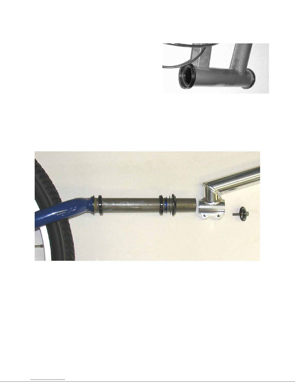
Figure 2.1. Headset cup placement
INITIAL ASSEMBLY
Modular frames should be bolted together firmly, as
soon as possible. Do not fully tighten any bolts until
all bolts are inserted and the nuts are on finger
tight. Be careful not to put weight on the frame
until all bolts are in and fully tightened; a partially
bolted frame can be easily damaged. Our frames
are fabricated with the frame sections bolted
together and WILL go back together; however, the
frame may need to be gently "tweaked" a bit to line
up the holes.
In order to put the vehicle on its wheels, you may need to install the front forks. The sequence
of cups, bearings, races and seals is illustrated in Figure 2. 2. The headset cups will normally be
already installed (pressed in) on most vehicles, and the bottom-most race (the "crown race")
will be pressed on the fork (may not be on framesets).
Figure 2.2 Headset, stem, head tube and fork assembly. From Right to left: Cap bolt, headset cap, stem,
upper cover, shim washer seal, compression ring, upper cartridge bearing, (cups are in the space between
the 2 bearings) lower cartridge bearing, lower bearing race/dust seal, and fork.
From the right; steering stem cap with bolt, stem, upper cover, shim washer seal, compression
ring, upper cartridge bearing , upper cup, head tube, lower cup, lower bearing, bearing
race/dust seal, crown of fork. The bearings we now use are sealed and only need a light coat
of grease to keep them from rusting.
Figures 2.3 and 2.4 show the installation. Slide the stem on above the headset upper cover,
place the steering stem cap on and using a 5mm hex key, tighten down enough so there is no
slop in the headset but not so much that the steering is stiff or that when you turn the
handlebars it feels ”crunchy”or tight. Sit on your cycle and align the handlebars, stem and front
wheel. Use a 5 mm hex key to tighten the two bolts holding the stem on.
Technical Manual 2-1
Page 5
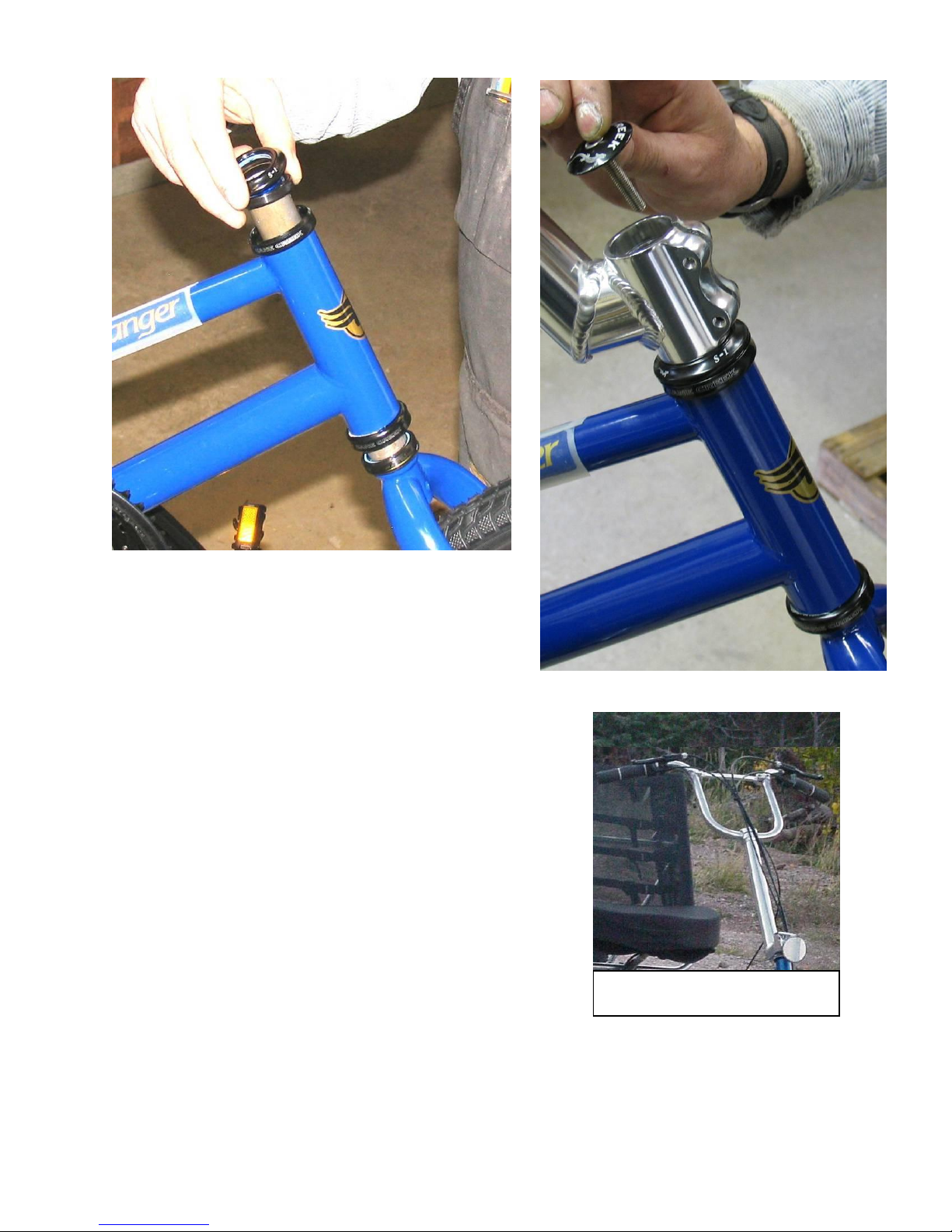
Figure 2.5. Tiller Steering setup
Figure 2.3 Above. Installation of fork into head set.
Figure 2.4 At right. Installing the stem.
INSTALLING HANDLEBARS AND STEM
Standard tiller steering includes a stem, either telescoping or
fixed-length. If telescoping, make sure that at least 2” are
inserted at maximum extension.
If your vehicle is a bike or trike with the 12” hi-rise bars", set
them in the stem so that the handle grip section just barely
reaches back and down. Trikes and four-wheelers with
"swept" bars actually may have a curve to the bar; set these
also so they reach back and down.
If a brace for the hi-rise bars is included with your model,
install it just below the curve of the handgrip area.
After the handlebar stem is put on the steerer tube (that
turns the fork), use a 5mm hex key to adjust the bolt
through the Star Fangled nut in the top of the head tube, to provide free movement of the fork
without sloppiness. The Star Fangled nut is set inside the steerer tube with a special tool. The
cap and bolt assembly thread into the Star Fangled nut and push down on the handlebar stem
and the headset bearings, thus creating the pressure that holds the headset together. Tighten
Technical Manual 2-2
Page 6
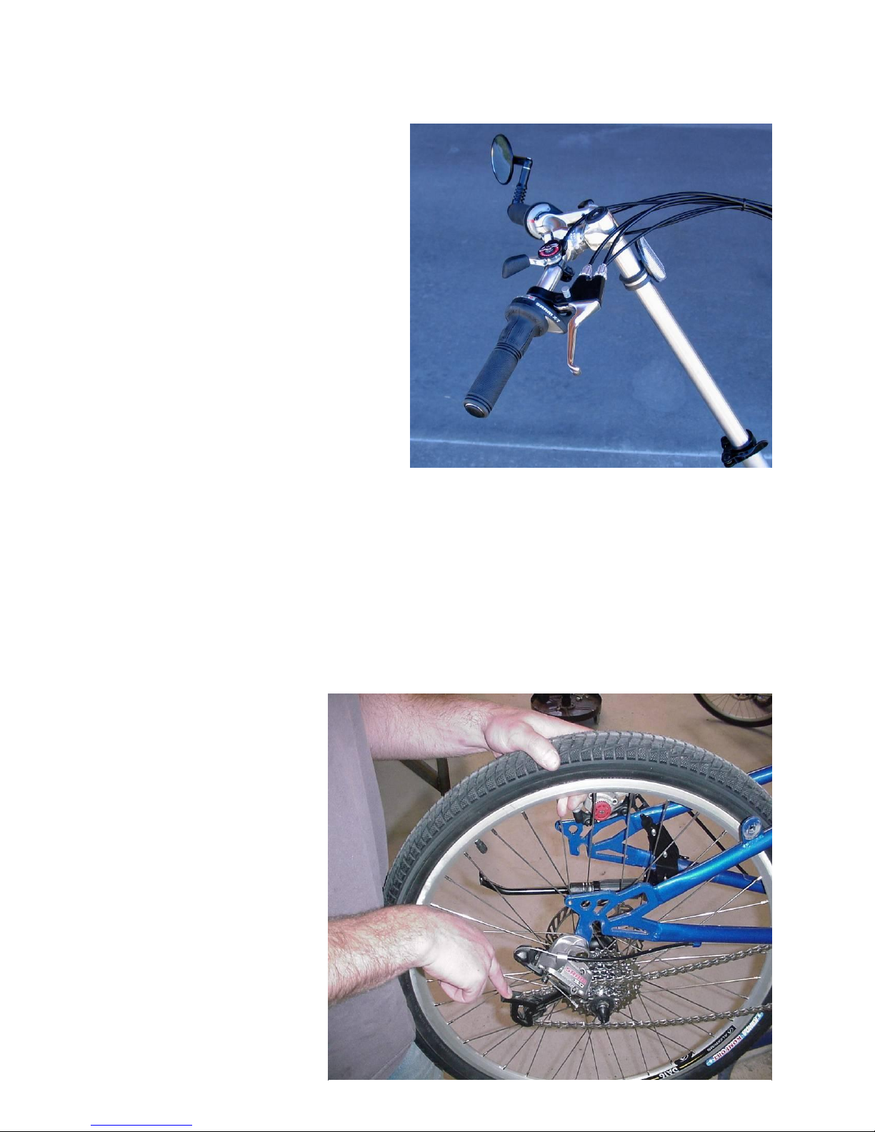
Figure 2.6. Installing the rear wheel
Figure 2.5a. Swept handlerbar and stem riser
the handlebar stem bolts that grip the steerer tube only after the headset is adjusted and
handlebars aligned.
Put three- or four-wheel vehicles on their
wheels as soon as feasible to avoid
damage to the components on the
underside of the vehicle. If you are
working on a two-wheeler, use a
mechanics stand or work on carpet to
avoid scraping the powdercoat finish.
We may have dropped your handlebars
on the stem riser so that we could pull
the stem riser out of the frame for
shipping. Please raise the handlebars back
up to the top of your stem riser when
you make your final fitting adjustments.
PARKING BRAKE
Most Lightfoot trikes have a dual pull
brake lever with a locking pin (see figure
2.5a). Some may also have an elastic band Parking Brake that holds the brake lever in the “on”
position. Activate it by squeezing either the front or rear brake lever and slipping the elastic
over the brake lever. The band stores on the grip when not in use. Use it when you are
loading your trike or parking it on uneven ground.
INSTALLING WHEELS
Some wheel axles may be quite tight in their fit into the "dropouts" (the slot that holds the
wheel axle) because of the very stiff nature of our frames, it may be difficult to get the axle
between the dropouts if the
fit is tight.
The disc brake rotor must be
aligned with the brake caliper
on the left side of the wheel.
There is a manual for
maintenance and operation of
your brakes in your owner’s
packet. Please familiarize
yourself with their operation.
While holding the derailleur
down and out of the way as
shown, position the wheel
into the base of the dropout,
then, as gently as possible,
work the axle up into the
Technical Manual 2-3
Page 7
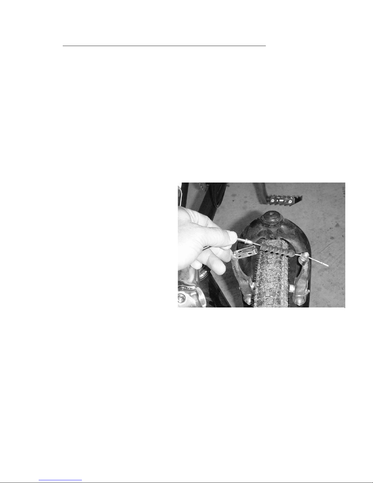
dropout, and the rotor (“disc”) into the brake caliper, without damaging the rotor or brake
pads. DO NOT handle brake rotors with bare hands; they are very sharp!
Wheels need to be centered before the quick-release lever is tightened. Usually the weight of
the bike on the ground will center the wheels between the frame forks. If we have preassembled the bike, the brake rotor will be centered between the brake pads when the wheel
is correctly aligned.
Some axles (narrower than our standard 135 mm length) come with spacers (flat washers) on
them; these go to the inside of the dropout to fill gaps between the axle nut and the dropout.
Knurled washers (if any, often found on internal hubs) go to the outside, under the axle nut;
these help grip and hold the axle in the dropout.
Internally geared rear hubs that do not have derailleurs should have the chain installed over the
sprockets and then be slid up the dropouts until the chain is drawn tight. All wheels should be
"eye-balled" or measured to make sure they are straight before final tightening. It is possible to
bend the axle if the wheel is not relatively straight or if the cycle is ridden with only one side
tightened. Make sure axle nuts are tight.
Wheels with internal hubs will have
“alignment washers”. Make sure the rightangle flange of the alignment washer is
positioned in the dropout slot; tightening
the flange against the dropout could bend
the washer or even the axle.
Most Lightfoot models are equipped with
disc brakes. Use Gloves when handling
brake rotor discs. Slide the wheels into
place being careful to place the rotor
between the brake pads.
NEVER PUT HANDS NEAR
BRAKES OR ROTORS WHEN
WHEEL IS TURNING!
To remove or install a wheel with V-brakes ("linear-pull" brakes); squeeze the end of the Vbrake arms together, and release the curved aluminum tube which holds the brake cable from
its slot. This allows the brakes to spring open and make room for the tire.
Wheels with the Nexus internal hub and roller-cam brake are more complicated to install;
please follow the instruction under "Internal Hub" below for attaching cables. Once the
internally-geared hub’s shifter cable is attached and the axle is in the dropout, the roller-cam
brake’s arm will be bolted to a clip attached to the frame. The rear "brake cable-stop" slides
into a slot on the brake "actuator arm"--the one dangling from the hub. The barrel adjuster
slides into a slot on the brake arm once it is bolted to the frame. The barrel adjuster and the
actuator arm are held in position by the tension of the "brake actuator return spring".
Technical Manual 2-4
Page 8
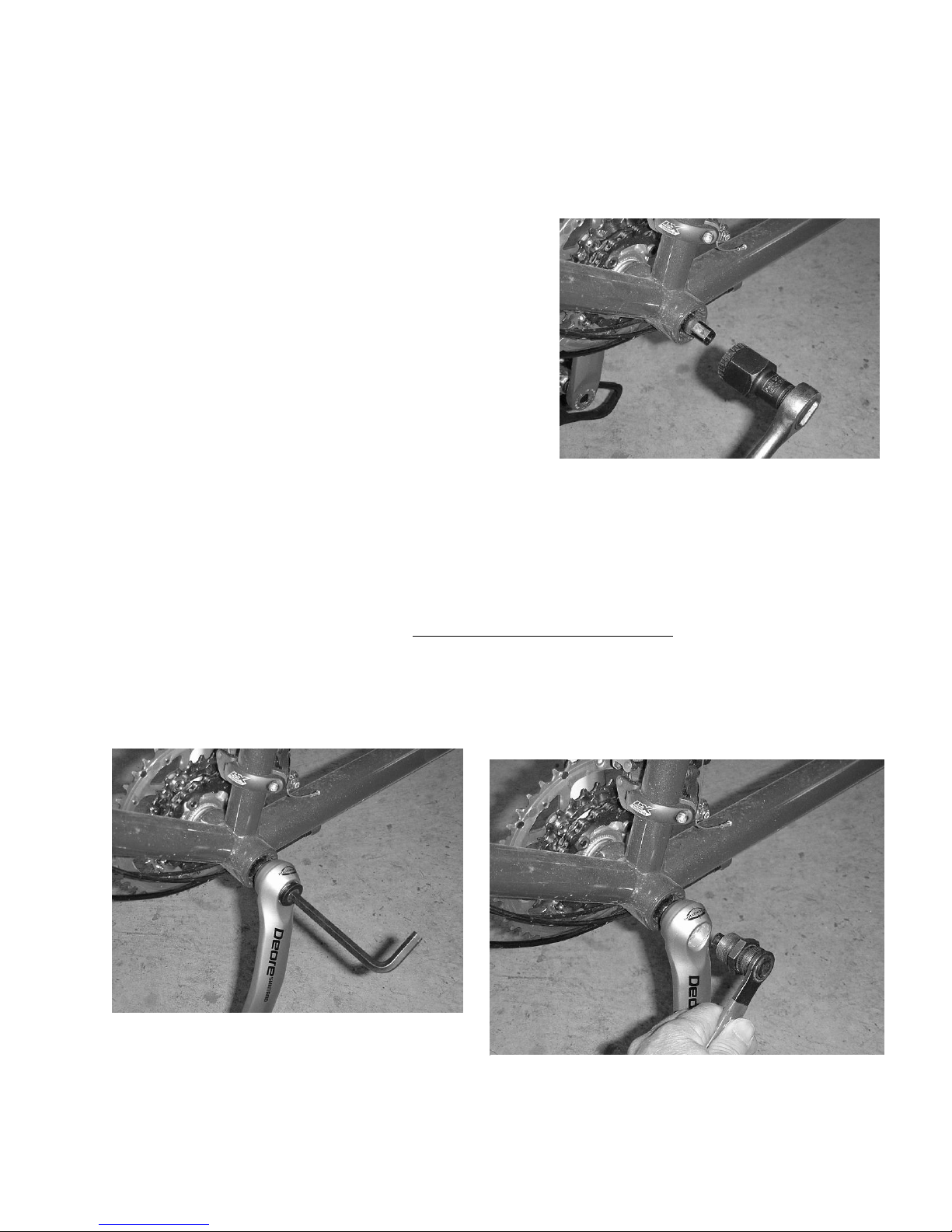
Figure 2.9. Installing the crankset
Figure 2.8. Bottom bracket wrench
Figure 2.10. Crank arm puller
A word about maintenance: The hubs we use are not “sealed” but are “semi-sealed”. They
come well lubed. The bottom bracket does not come apart; it is maintenance free. IF the
threads start to "creak", back them out and grease them. They were well greased here. The
hubs will need some maintenance. We suggest twice a year lubing them.
THE BOTTOM BRACKET, CRANKSET AND
PEDALS
The bottom bracket bearing set may be already installed,
but may not be on framesets. If not, a special bike tool
is required to tighten it within the threaded "bottom
bracket shell".
The crankset is held on the bottom bracket spindle with
the included crankset bolts. Most cranksets are held on
with socket-head bolt, tightened with an 8mm Allen
wrench. Some types use a hex head bolt and a socket
wrench is needed. These bolts should be slightly
greased.
Wipe off any grease where the crank spindle slides into the crank arm--no more than a thin film
of grease is needed to keep the cranks from seizing onto the spindle. The crank with the
attached sprockets goes on the right side.
Pedals can be installed after the crank arms are on, so that the vehicle holds the arms--this
makes installing the pedals a bit easier. The left pedal is reverse-threaded. An open-end pedal
wrench is essential if you are going to remove and install the pedals frequently. Do not simply
hand tighten the pedals, as they may work loose and ruin the crank arm.
Maintenance: The bottom bracket does not come apart, it is maintenance free. If you begin to
feel a clunk or gritty spot, a bearing has gone out and it is time to replace the unit.
Technical Manual 2-5
Page 9
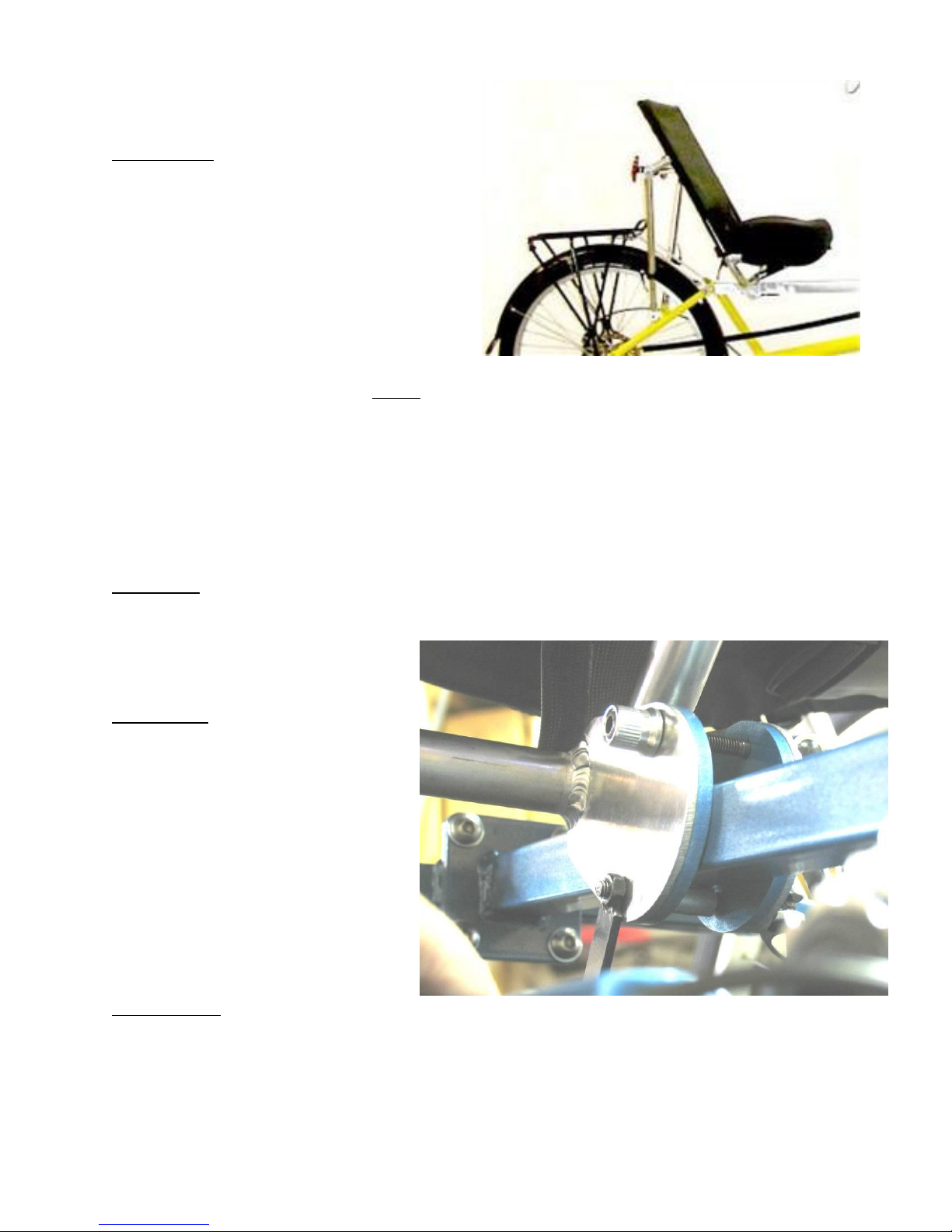
Figure 2.11. Mesh seat
INSTALLATION AND ADJUSTMENT
OF THE SEAT
Installation: Slide the two top pockets of the
seat cover over the top posts on the seat
frame. Slide the pocket of the seat bottom
over the seat horn. Buckle the large strap
around the seat supports and under the seat
fabric. Pull quite tight. You don’t want the
seat to bottom out on the frame.
Buckle the back straps starting at the top.
The top three straps should be tightened as
tight as they will go. The next two straps
should be tightened incrementally looser so
that the bottom strap follows the curve of the seat back. This allows for lumbar support and
can be adjusted to suit your needs. See more on this below.
Place the pad on the seat using the velcro to hold it in place.
Place the seat on the square rail and adjust it for the rider. Screw the quick release bolt into
the clamp while the lever is open until it snugs down when closed.
For Bikes: Attach the seat braces to the seat brace slotted tab on the rear frame of the bike.
Place the seat brace to the outside of the tab with the nylon washer between the slotted tab
and the seat brace. Tighten the nut
and bolt so that the seat brace does
not slip.
For Trikes: Attach the seat braces to
the seat brace slotted tab on the rear
frame of the bike. Place the seat
brace to the inside of the slotted tab
with the nylon washer between the
slotted tab and the seat brace.
Tighten the nut and bolt so that the
seat brace does not slip.
Figure 2.12. Seat clamp on Greenway
and RoadRunner trike
Adjustment: Adjust the seat braces so that the seat bottom supports are roughly parallel to
the ground. IF the seat is tipped too far forward, the horn will not be effective and the rider
will feel that she is falling out of the seat. Riding in a more recumbent position may require
shortening the horn.
When sliding the seat, push or pull as much as possible in the center so the tabs won’t bind.
Technical Manual 2-6
Page 10
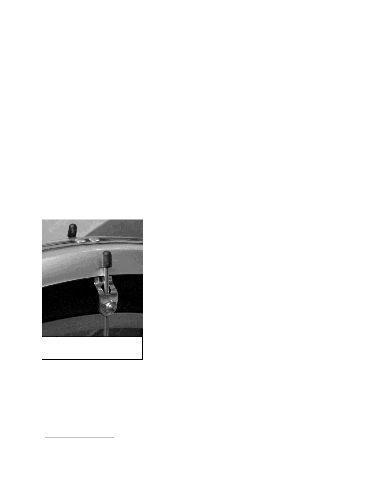
Figure 6.7. Fender stay
adjustment
Release ALL 4 quick release bolts and/or pinch barrel bolts during adjustment, even if
adjusting only one part of the seat.
For Greenways and RoadRunners: The lower quick release bolt on the seat clamp should have
a small wing nut on the chain side ( as shown in figure 2.12) and spacers to “shorten” the bolt
on the left side of the trike. IF it doesn’t, in some positions, the nut will interfere with the
cassette.
To adjust the contours of the mesh Performance seat, adjust the tension of the straps on the
back of the seat and under the seat bottom. Most people will want the straps behind the small
of the back (the lumbar region) to be tighter for more support, while the straps at the very
bottom of the back will remain quite loose. The seat horn can be adjusted in two ways; reduce
the contour that the horn creates by tightening the large strap under the seat, and increase the
horn contour by substituting a longer piece of 5/8” dowel and/or loosening the large strap.
The rear edge of the seat pad cover has a Velcro closing that can be opened to allow the
removal, modification or replacement of the seat pad.
All the nylon straps as well as the mesh itself will stretch a little during break-in. Readjust the
straps as needed to keep the seat comfortable for you.
FENDERS (FROM CHAPTER 6 OF TECH MANUAL)
Front Fenders All of our front fenders require that
the left stay have a 30 degree bend 3” behind the
fork mount loop to clear the brake caliper. On 20”
front fenders, we trim the backside so it will not scrape
going over curbs and bumps. The front fenders have single
stays instead of double stays.
INSTALLATION
1. Bolt the fender top tab to the FRONT of the fork using
6mm x 2” bolt, lock washer and nut. Center the fender
over tire and tighten.
2. The left fender stay needs a 30 degree bend 3 inches
behind the attachment loop to clear the front brake caliper.
We usually do that for you. If you have to bend it, just make sure the bend is in line with the
flat plane of the loop.
3. Attach stays to the 5mm threaded mounts in fork using 5 mm bolt and washer.
4. Adjust stays to center fender over the wheel by loosening the stay nuts and sliding the stays
while centering the fender.
5. Tighten all nuts. Trim the ends of the stays with bolt cutters or hacksaw if you choose. File
off sharp edges and replace end cap. A dab of finger nail polish or glue will hold them on well.
Rear Fenders on Bikes Set up fender hardware as directed in instructions with this exception:
the front mount on the rear fender should be installed by bolting from the inside of the fender
Technical Manual 2-7
Page 11

Figure 6.8. Jackshaft, fender and brake setup
to the fender mount on the frame. Use two or more 1/4“ nuts as spacers between fender and
frame if needed.
Rear Fenders on Trikes 1.Place the fender on
the rear wheel. Open the Stays to approximate
width needed for mounting. 3. Bolt the stays to
the frame loosely. 4. Position the front of the
fender to the front of the outrigger above brake.
Use 5mm screws with flat and lock washers
from the inside of the fender to attach to fender
mount. 6. Adjust and tighten bolts and screws all
around when sure of fit. 6. After Stays are
adjusted, they may be cut off with bolt cutters,
filed and have caps placed on their ends—be
careful of the sharp cut ends.
Technical Manual 2-8
Page 12

WHEELS AND TRANSMISS
WHEELS AND TRANSMISSIONS
W
HEELS AND TRANSMISSWHEELS AND TRANSMISS
MOUNTING TIRES ON WH
MOUNTING TIRES ON WHEELS
MOUNTING TIRES ON WHMOUNTING TIRES ON WH
Install a rim strip or rim tape; this protects the tube from punctures caused by the tips of the
spokes and the spoke nipples. Align the hole in the rim strip for the valve stem with the hole in
the wheel rim.
Some tires have a certain rotating direction marked on their sidewall. Generally, any V in the tread
pattern should open toward the rear of the direction of tire travel. On our trikes, we often
mount the right rear wheel with the cassette mount on the inside, but it doesn’t really matter.
Mount one side of the tire on the rim, and then push the
inner tube into the partially mounted tire. Make sure
the tube is not folded or twisted. After the valve stem is
situated, use the tire levers to force the second side of
the tire onto the wheel rim. Take care not to pinch the
inner tube as you go. Some tires may prove to be very
tight and difficult to lever onto the rim; warming and thus
softening the tires--as well as lubricating with soapy
water--may help get them on.
Before inflating, rotate the tire and tube around the rim
as needed until the valve stem sticks straight out of its
hole. Inflate slightly and, before inflating further, check to
make sure that the tire is seated evenly on the rim.
Finally, inflate the tire to its highest recommended pressure.
Some of our vehicles utilize high pressure (80 to 110 psi) tires for lower rolling resistance on
pavement. Many tire models on the market are rated for a maximum of 45 to 60 psi. Sometimes
Figure 3-2. Tire Assembly
EELS
EELSEELS
Figure 3-1. Rim Strip
people choose to inflate these medium-pressure
tires over the rated pressure so that they roll
more easily. Be aware that over-inflation is not
recommended by the tire manufacturer.
If the tire still does not want to seat correctly,
then deflate to 15 or 20 PSI. Squirt some Windex
or dish soap on the trouble spot making sure to
work it in below the bead. Then re-inflate the tire
to desired PSI. The lubrication should help the
tire to seat itself.
For safety reasons, insert the quick release axle
into the wheel so that the quick release handle is
on the side opposite the disc brake if at all possible.
IONS
IONSIONS
Technical Manual 3-1
Page 13
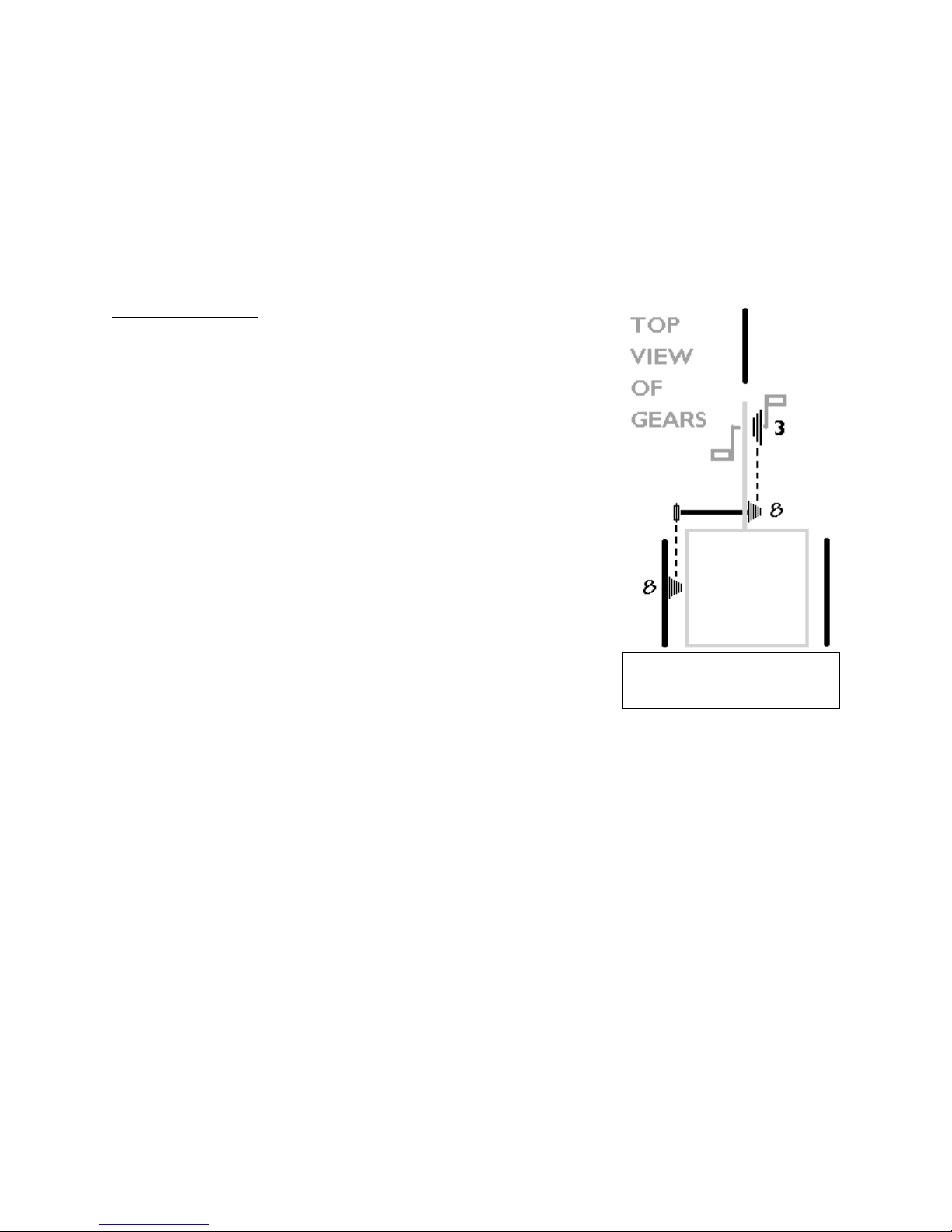
gears on a trike.
T
RANSMISSIONS
TRANSMISSIONS
TRANSMISSIONSTRANSMISSIONS
Our standard transmission for a single-seat three- or four-wheeler is illustrated
below. The pedals are attached to a triple-sprocket crankset, which creates rotation (by means of
a chain) of an 8-speed gear cluster on a jackshaft (thus turning the jackshaft). A single sprocket on
the outer end of the jackshaft then creates rotation (by chain) of the 8-speed gear on the left rear
wheel--the drive wheel.
Two-wheel drive is a custom option, wherein the jackshaft is extended to the right to drive the
right rear wheel as well.
Trike Compound Gears
Trike Compound Gears
rike Compound GearsTrike Compound Gears
T
When all three gear clusters are in low, the resulting gearing is very
"low", "slow" or "powerful". This means that one revolution of the
pedals will produce only a small forward motion of the vehicle.
The force required to turn the pedals in low gear is very little; thus
pedaling is easy.
When all three gear clusters are in high, the resulting gearing is very
"fast" or "high". One revolution of the pedals will produce a lot of
forward motion. Unless the vehicle is already moving fast, the
effort required to turn the cranks will be very great. The very
highest gears are used only at high speeds on downhills, with the
help of gravity.
The term "Gear Inches" is shorthand for describing the "size" of
gear you are in. Being in a "90 gear-inch" gear is like pedaling an
1890's high-wheeler with a 90" diameter wheel and fixed pedals; a
single turn of the cranks and you go a long way forward. This is
called a "tall" or "high" gear. Being in a "10-inch gear" is like
Figure 3-3 Top view of
pedaling a little kid's trike with 10" diameter wheel (a "low" gear);
you don't make much forward progress for each turn of the cranks, though pedaling is relatively
easy. Being in a 26 gear-inch gear on a mountain bike with 26" diameter wheels means that for
each turn of the pedals, the drive wheel goes around exactly once. In a 52" gear, the drive wheel
goes around exactly twice for each revolution of the cranks.
As normally set up; the left hand shifts the front triple sprocket by means of a twist-grip shifter.
The right hand shifts the middle 8-speed cluster, also using a twist-grip shifter. A third shifter (a
thumb lever) is used to shift the rear 8-speed cluster. The rear cluster is shifted only occasionally,
and is normally left in a position to give an appropriately low gear for the conditions in which you
are riding.
Contrary to some assumptions; single-wheel-drive on a trike (as Lightfoot Cycles uses it) with
appropriate tires almost always provides plenty of traction, even in snowy or gravelly conditions.
Single-wheel-drive also does not create any difficulties with tracking (traveling straight ahead) on a
properly laid-out long-wheelbase design, despite the fact that only one side of the vehicle has
power. Electric assist and two-wheel-drive options create two different forms of very positive
dual-wheel traction.
Technical Manual 3-2
Page 14

Page 15

recommend hairspray or any solvents that might damage the gel grip. You may have to trim the
g
rips; they may be a bit too long to fit on some handlebars with certain components.
Standard placement of the shifters connects the left grip shifter to the front triple chainring. The
right grip shift controls the rear derailleur on bikes, or the mid-frame derailleur on trikes and
quadracycles. On trikes and quadracycles, the thumb shifter controls the rear derailleur.
If an internal hub gearing system is used, then the right grip shift will control the internal hub in the
rear drive wheel, and the thumb shifter will control the mid-frame derailleur. This allows the most
commonly shifted gears (the internal gear hub) to be those most easily shifted, and leaves the
rarely-shifted “ranges” to be controlled by the more awkward thumb shifter.
The derailleur shifted by the thumb shifter is generally shifted only infrequently and is used to set a
"range" of operation such as low range, medium or high range.
ROUTING THE CABLES
ROUTING THE CABLES
ROUTING THE CABLESROUTING THE CABLES
Try to keep the length of the cable housing as short as possible, however; do not make tight bends
in the housing. Zip ties can be used to tie loose sections of cable to the frame.
The cable "saddle" is used to activate both rear brakes as shown in Figure 3.5. Place it about 3
inches in front of the mid-frame cable saddles. Before installing it, place a patch of frame protector
in the spot it will sit. This will protect the frame from scratching and noise.
Figure 3.6. Trike shift cable arrangement
Technical Manual 3-4
Page 16

Page 17

Page 18

F
ront derailleur adjustment is not an exact science. It requires a good eye and a bit of patience to
get it right. When you apply power to the pedals, the power is transmitted to the rear sprockets
by the upper run of the chain. The lower run of the chain is just the return path, and the only
tension on the lower run is that applied by the spring in the rear derailleur. Since the front
derailleur does its shifting with the upper, power-transmitting, section of chain, it has a harder task
to perform. In general, you should not expect a front derailleur to shift well while you are pedaling
hard, even if the rear derailleur does so.
The Three Front Derailleur
The Three Front
e Three Front The Three Front
Th
Clamp Position
The most critical adjustment of a front derailleur is its attachment to the bicycle frame. This must
be set correctly before you attempt to adjust the limit stops. There are two variables, angle and
height. The front derailleur comes with a small piece of plastic holding it into the extended (highgear) position. A small piece of clear plastic stuck to the side shows where the teeth of the
sprockets should meet the shifter when in high gear; this tells how high to mount the derailleur. As
you tighten the clamp, watch to make sure the derailleur cage remains parallel with the sprockets.
Remove the plastic spacer after the derailleur is firmly clamped to the frame.
of the front derailleur is judged by looking down on the cage from above. Modern front
Angle
derailleurs have very subtly shaped cages, so it is not always easy to tell when the ideal adjustment
has been made. In general, the centerline of the cage should be parallel to the centerline of the
frame. Rotating the derailleur so that the back of the cage is farther out will sometimes improve
shifting to the small ring of a triple by preventing overshifting, but may cause increased need for
trimming on the larger rings. It may also cause the crank to strike the cage.
Rotating the derailleur so that the front of the cage is farther out will help reduce the need for
trimming on the large chainwheel, and will provide crisper downshifting, but with a greater
tendency to overshift on the inside. This may be appropriate on bicycles equipped with an antiderailment device.
Height
recommend 2mm clearance between the bottom of the outer cage plate and the teeth of the
large chainwheel. This is a bit of an oversimplification. Best performance will result from the very
lowest position that still just barely keeps the cage from hitting the chainwheel teeth.
The lower you can get it, the better it will shift, and the less you will need to trim the front
derailleur.
Derailleur Chain wheel Mismatch
Derailleur Chain wheel Mismatch
Derailleur Chain wheel MismatchDerailleur Chain wheel Mismatch
To get the front derailleur as low as possible, the curvature of the outer cage plate has to match
the curvature of the largest chainwheel.
If you use a larger chainring than the derailleur was designed for, the rear of the cage will hit the
teeth of the big chainring before the front of the cage gets low enough to provide crisp shifting
without the need for trimming.
If you use a smaller chainring than the derailleur was designed for, it will shift OK, but you'll have to
do a fair amount of trimming, due to the rear of the cage being higher than it should be, so that
the chain crosses through it farther back.
Lately I've started modifying front derailleurs for improved shifting with larger rings. I have an RSX
on a bike with 50/38/28 Biopace (the sweep of a 50 Biopace is comparable to that of a 52 round.)
The RSX front derailleur works great on its intended 46/36/26 setup, but the cage doesn't match
the curve of the larger chainring. In a couple of minutes with a grinding wheel, I removed a good
bit of metal from the bottom rear of the outer cage plate, and a bit from the bridge section where
of the front derailleur is a principal factor in how well it will shift. Manufacturers commonly
Derailleur Adjustments
DerailleurDerailleur
Adjustments
AdjustmentsAdjustments
Technical Manual 3-7
Page 19

the inner and outer cage plates connect at the back. This made the derailleur match the curvature
o
f the larger chainwheel, and allowed me to set it low enough to provide good chain control. This
setup now works fine with an STI rig that doesn't permit "trimming" the front derailleur.
Low-gear limit stop.
The low-gear limit stop stops the derailleur from shifting past the smallest chainwheel and throwing
the chain onto the bottom bracket shell. If it is too loose, the chain will fall off when you try to
downshift to the small chainwheel. If it is too tight, you it will be difficult or impossible to shift
down to the low chainweel.
On older front derailleurs, the low-gear stop is the one closer to the frame. Many newer designs
reverse this position for reasons relating to the mechanism used.
The basic adjustment for the low-gear stop is to set it so that the chain just barely clears the inner
plate of the cage when the lowest gear (small front, large rear) is selected. This will usually be the
best position for double-chainwheel setups, and will permit the use of most or all of the rear
sprockets with a minimum of trimming.
For triple chainweels, it will sometimes be necessary to adjust the low-gear stop a bit looser, so
that the outer plate of the derailleur can travel far enough to knock the chain off of the middle ring.
Anti-derailment devices
In some instances, you may find that one adjustment of the low-gear stop causes the chain to
derail past the small chainring, but a tighter setting results in slow downshifting to the small ring.
In such cases, a good, if inelegant, solution is sometimes to install an anti-derailment device that
clamps to the seat tube. These products, such as the 3rd Eye Chain Watcher ® and the N-Gear
Jump Stop ® set up a barrier preventing the chain from overshooting the small ring, no matter
how loose the low-gear stop is set. This allows the low-gear stop to be set to allow the derailleur
to move farther inboard for faster, more precise shifting, even under some load. These devices can
often save the day when extra-wide range gearing is used on a mountain bike or tandem.
High-gear limit stop
The high-gear limit stop is pretty straightforward. It should be set so that the chain almost rubs on
the outside plate of the front derailer cage when the bicycle is in its highest gear (large front/small
rear). This will reduce the need for trimming as you shift the rear derailer.
If the shift to the large chainwheel is slow, make sure that you aren't pedaling too hard, front
upshifting requires being ready to have the cranks slow down when the shift takes place. If the shift
is unreliable even when you are pedaling lightly, you may be able to improve it by loosening the
high-gear stop a bit. If you do so, check to make sure that the derailer cage is not moving so far
out that it can be struck by the crank as it goes by.
Sometimes front upshifting may be improved by rebending the front edge of the inner cage plate
outward a bit. This may be done with an adjustable wrench. This is rarely necessary on modern
front derailers, but used to be a very common trick on older, cruder designs.
Front Derailleur Trimming
Front Derailleur Trimming
Front Derailleur TrimmingFront Derailleur Trimming
As you shift the rear derailleur one way or another, the direction from which the chain runs from
back to front changes a bit. As a result, sometimes it is necessary to "trim" the adjustment of the
front shifter after changing gears with the rear, even if you are staying on the same front chainring.
Technical Manual 3-8
Page 20

Trimming means using the shifter to move the front derailleur cage sideways just a little bit, enough
t
o stop the chain from rubbing, but not enough to make it shift to a different chainring.
Older front derailleurs designed for friction shifters used to require trimming as a matter of course,
but newer indexed systems can often be set up so that no trimming is necessary.
For a "trimless" front indexing, you will usually need to be using the particular chainwheel sizes for
which the front derailleur was designed, and the chainwheels must not be bent even a little bit.
The lower down the cage is mounted, the less trimming will be needed.
If your system requires trimming, it is essential that you do it. If you ride with the chain rubbing
against the front derailleur cage, you will wear a groove in the side of the cage and it will never shift
properly.
Adjusting
Adjusting derailleur systems
AdjustingAdjusting
turn freely. Make the initial "rough" adjustment without the chain installed. Fine-tune and test with
the chain in place.
Rough Adjustment:
position if it is the front derailleur). The shifter cable should be either disconnected or the shift
lever at the handlebars should be in the position in which it is taking up the least amount of cable.
(Note: the shift lever should be complementary to the derailleur in model or type.)
Then screw in or out the little "high/low limiting screw" that restricts the movement of the
derailleur in and out; this establishes how far the derailleur can move, so that it does not shift the
chain entirely off the sprocket cluster. There are two of these, usually marked with an H for high
(small sprocket) and an L for low (large sprocket). Move the screw until the derailleur jockey
wheels line up with the outermost cassette sprocket. Manually, push the derailleur to its other
extreme and adjust the other limiting screw until the derailleur lines up with that sprocket or chain
ring (front). The instructions that come with your front derailleur give metric settings for making
this adjustment. Return the derailleurs to their relaxed position. Above smallest chainring and
sprocket.
Now, Install the chain and connect the cables. Make sure that the housing (the tube in which the
cable is housed) is socketed into the mechanism or cable stops at each end by stretching the cable
under the midframe after everything is connected. Disconnect, take up the slack and reconnect.
When the shift lever is now rotated (while pedaling), the derailleur should shift the chain from one
sprocket to the next. When the derailleur reaches the farthest sprocket, re-adjust the “low” limiter
screw to permit the chain enough movement to shift onto the sprocket, but not so much that it
goes off the far side.
If the system is an index system (as most LFC vehicles are), fine-adjustment to exactly position the
rear derailleur for accurate shifts is generally made with a "barrel-adjuster" bolt, either where the
cable enters the derailleur or where the cable exits the shift lever. If your chain hesitates to shift
up (to the smaller sprocket), twist the barrel adjuster inward, thus taking some of the tension off of
the cable. If the chain does not shift down (to the larger sprocket), twist the barrel adjuster
outward, adding tension to the cable so that it pulls the derailleur further over toward the larger
sprocket.
derailleur systems is most easily done with the drive wheel elevated into the air so it can
derailleur systemsderailleur systems
with
withwith
Start by letting the spring-loaded derailleur relax to its highest position (lowest
Technical Manual 3-9
Page 21

I
ndicator marks for the front derailleur (even on index systems) do not accurately indicate what
gear the front triple sprocket is in. This is not a problem, but you can take the time to adjust it as
close as you wish.
The shifter for the rear-most derailleur on a trike or Tandem is a "friction shifter". The limits to
derailleur movement are adjusted in the same way as for the index shifter, but there is no need to
fine tune the operation of the shifter lever. Shifting is done by sound, sight, and feel. After a
learning period, this can be done fairly accurately without looking. The screw or "D-ring" on top of
the shifter can be tightened to adjust the tension of the thumb lever; it should not be so tight that
it is difficult to shift, but not so loose that the derailleur spring pulls the cable back out of gear.
You will be able to shift those "range" gears if you are climbing steep hills, starting heavy loads or
ying down a hill and need more gears. Generally, leave it in a center gear unless you are
fl
experiencing one of those conditions.
It's a tight squeeze on that shifter to get all 8 gears. Most of the time it can be set up to get all 8,
but occasionally only 7 are available. Don't get too excited if only 7 are available, You will still have
168 gear combinations. If it ever needs to be adjusted, you can have it set up for whichever end
you need the gears most, High or low.
JACK
JACK----SHAFT
SHAFT
JACKJACK
SHAFTSHAFT
The Jack-Shaft transfers power from the centerline to the outside drive wheel on trikes and some
quads. PROPER CARE AND MAINTENANCE IS CRITICAL FOR GOOD FUNCTION AND
REPLACEMENT EASE. Remove, clean and grease the parts every 1000 miles or each year.
Remove any burrs that develop around bolt holes with a round file or sandpaper. Check the bolts
holding the freewheel and cassette mounts frequently
frequently to make sure they are tight. Sloppy bolts
frequentlyfrequently
create burrs which will make removal of the jackshaft almost impossible.
Technical Manual 3-10
Page 22

Page 23

Page 24

Page 25

Page 26

Figure 4
-
2. Four wheeler front end
STEERING
STEERING
STEERINGSTEERING
LINKAGE STEERING
LINKAGE STEERING
LINKAGE STEERINGLINKAGE STEERING
Lightfoot’s Linkage Steering System consists of
these parts:
1. Handlebar and stem
2. Stem extension
3. Linkage Steerer Tube (inserts into bike
frame)
4. Linkage Rod
5. Fork Steerer Tube Clamp/Cap
6. Steering Assembly Standoff
7. 2)5/16” tie rod ball ends
8. 2) 5/16” Fine Thread Nuts
Adjust the steering columns so that they align
with the front wheel. The Steering Assembly
Standoff should be in line with the long axis of
the cycle. The tab on the Steering Assembly
Standoff and the Fork Steerer Tube Clamp
should be parallel to each other and
perpendicular to the long axis of the cycle. The
handlebars should be perpendicular to the long
axis of the cycle and especially the front wheel.
Tighten all bolts when everything is aligned.
DUAL WHEEL
DUAL WHEEL ALIGNMENT
DUAL WHEEL DUAL WHEEL
The steering linkages on the front of the four-wheel vehicles will in most cases come pre-adjusted
if the vehicle is assembled. Some may not be adjusted; you can tell this if there is excessive "toein", or if the front tires obviously "scrub" as you make a tight turn.
ALIGNMENT
ALIGNMENTALIGNMENT
Figure 4-1. Linkage Steering
Technical Manual 4-1
Page 27

You may also want to make adjustments to the "quickness" of the steering. You may need to read
the following paragraphs a couple times to make sense of these instructions. Adjustment is made in
one of three ways. Fine toe-in adjustment is made by unbolting one end of the tie-rods and
screwing the tie-rod-ends in or out. Ackerman adjustment can be made by rotating the head
stems on the steering tube of the front fork.
Akerman Steering
Akerman Steering
Akerman SteeringAkerman Steering
Ackerman steering is the design of the vehicle that allows the inside wheel to turn more sharply
than the outside wheel in a turn, thus avoiding "scrubbing" of the front tires and losing speed during
turns. It is adjusted by changing the angle of the stem that holds the outer tie rod bolt, in its
relationship to the front wheel. The amount of angle depends upon the wheelbase (length) and
track (width) of the vehicle. A short vehicle will have a wide Ackerman angle, with the outer stem
and tie-rod end angled 20 to 30 degrees from the long axis of the cycle. A very long wheelbase
vehicle may have only a 10 or 15 degree Ackerman angle. When correctly adjusted, sharply
turned front axles should aim at the same point just below level on an imaginary line drawn
through the rear axle(s) at right angles to the long axis of the cycle.
Toe
Toe----in
in
ToeToe
inin
Toe
Toe----in
in measures the amount that the wheels are out of parallel with each other. The front wheels
ToeToe
inin
should be 1/8" closer together at their front than at their rear (when pointing ahead). The rear
wheels should be parallel to each other. Make sure that the nuts that hold on the tie rods are
TIGHT.
Quickness of Steering
Quickness of Steering
Quickness of SteeringQuickness of Steering
Steering "quickness" can be adjusted if you find the vehicle handling to be TOO quick. By turning
the direction that the outer tie-rod bolts are facing so that they reach forward, you can reduce by
a small percent the "quickness" or amount that the wheels turn with a movement of the
handlebars. For a dramatic reduction in steering quickness, you can replace the center stem that
holds the center tie-rod bolt with a comparable, but shorter stem.
Technical Manual 4-2
Page 28

Figure 6.1. Canopy
with sides rolled up
OPTIONS AND ACCESSORIES
CANOPIES
You will need a drill with 3/16" bit, screw driver, 3/8” wrench and
(8+) 1 1/2" #10bolts and locknuts. Attach the Canopy pedestal to
the fender platform with 1 ½” x ¼ “bolts and lock nuts. Position it
on its center 17 1/2" forward from the back of the vehicle. They
should be on top of the fender panel, to the outside of the fender
panel frame.
The footman-loops of the canopy top may be fastened as close as
possible to the outside corners of the fender platform or the cargo
box with #10 bolts. They are secured the same way, with bolts or
rivets.
Assemble the bows as you put them into the canopy. The shortest bow belongs in the center.
The front and back bows are the same length. Attach the front and back bows to the swivel
plate using 1 ¼” x ¼” bolts and lock nuts. Attach the center bow to the swivel plate and the
pedestal with the 2” x ¼” bolt in this order: bow, plate, 4 washers, pedestal, lock nut. This will
take two people or a support for the other side. The bows have spring in them to give a curve
to the top of the canopy. Tying a piece of twine around the uprights of the center bow will
keep them from springing out as you work on them
Attach the straps to the canopy as follows: the shortest strap goes around the front and back
bows and through the footman loops. The other two straps go through the front and back
footman loops on the bows then down to the footman loop on the platform. Snug these down
so that the canopy top is level. Adjust the straps to get the proper attitude and tautness.
Attach the canopy sides to the velcro around the top of the cargo box.
On four wheeled cycles, you may have a front strap which attaches to the front frame cross
member. It should not interfere with steering at any point.
The fabric can be cleaned without being removed from the frame. Brush off any loose dirt,
hose down and clean with a mild soap in lukewarm water (no more than 100 degrees.
CARGO HAMMOCK
Align the cargo hammock in the opening. Fasten the nylon straps snugly around the framework
between the wheels. There are 4 or 5 straps per side. Near the brake rotors and derailleurs,
be sure to tuck the ends of the straps into the loop made around the frame to keep strap ends
out of the rotors and gears.
Cargo Hammocks can be hand washed or wiped with a cloth to keep clean. Do not wash in a
washing machine or dry in a dryer.
Technical Manual 6-1
Page 29

Figure 6.2. Chain Tubes
CHAIN TUBES
Chain Tubes function to keep the
chain cleaner, keep the rider
cleaner and support the chain on
large trikes, bikes and four
wheelers.
Chain Tube Mounting Mount
chain tubes as shown in Figure 6.2.
Keep bolts loose enough to allow
the tube and bracket mount to
swivel with different chain
positions, but not so loose that the
frame mount will twist out of
alignment.
Bikes: Mount clamp on mid frame brace using “p-clamp”(figure 6.2).
RoadRunner trike: Mount clamp on bottom tube 3-¾ inches in front of the mid-frame brace.
Align clamp with axis of cycle. Break chain below and behind the crank with chain tool and run
the chain through the tubes, threading correctly through the front derailleur. Reconnect chain
and be sure to work out any tight spot on the chain by flexing the chain back and forth from
side to side.
If necessary, loosen the tube clamps and reposition the tubes so that they are at least 1-½
inches from either sprocket. It is important not to pedal backwards when chain tubes
are on the cycle. If poorly adjusted, they may foul in the sprockets.
CHAINRING GUARD
The Lightfoot Chainring guard is
made to install on the Truvativ
Blaze Crankset. Slip the guard
over the crankarm and install the
bolts closest to the crank arm
first. Use #4x ½” or M3x 16mm
bolts, use an 5mm nylon locknut
between the guard and the outer
chainring as a spacer and tighten
using locktite or peen the tip of
the bolt to insure the nut stays
on.
Technical Manual 6-2
Page 30

Figure 6.3. Electric assist on trike
DECALS
Apply decals at 68 –75 degrees F. Clean the frame and your fingers with alcohol. Peel back off
the decal keeping fingers off the adhesive; use tweezers if you have no fingernails. Position
decal. Lay on frame. Use a credit card to “burnish” or set the decal working from center to
outside, pushing any air bubbles as you go.
Remove top cover by peeling back along the frame. Lifting may lift the decal especially if cold.
If you have trouble, allow the decal to sit for 24 hours with the cover on then remove cover.
Do not use citrus-based cleaners on decals; they will smear. Alcohol or ammonia based
window cleaners are OK.
ELECTRIC ASSIST
The electric assist system
battery pack rides in the
cargo hammock of our trikes,
and can ride on top of almost
any rear rack that is mounted
on our bikes. A red and a
black wire from the motor
pass through an opening in
the front of the cargo
hammock (or cargo box), and
attach to a similar pair coming
out of the front of the battery
pack; this connector clicks
together and apart easily. A grey cable from the motor attaches to the throttle. Unzip the
battery pack to see the pair of 12 volt sealed batteries wired in series inside. A silver metal
connector lies beside the batteries; this connects to the battery charger. The battery charger
can be carried in the cargo hammock (rough usage can be hard on the electronics of the
charger), or it can be left at the charging station. The battery pack rests on a platform that
serves to spread their weight across the fabric bottom of the hammock. If you wish to put a
piece of foam rubber under the platform, it will help reduce road shock to the batteries (and
charger if you carry it). Push the battery pack forward as far as possible to keep cargo room
available.
Technical Manual 6-3
Page 31

Figure 6.6 Upper fairing mount for linkage
steering
Figure 6.4. Lower fairing mount, 20 and 26" fork
Figure 6.5. Upper fairing mount for tiller
steering
Figure 6.65 – Fairing on suspension fork
When shifting, ease off of the throttle, so
that the shift is smooth. If you have the
assist in too high of a gear when starting up,
it will surge or stall.
FAIRING
The fairing mounts with T-Block clamps with
arms on the handlebars. The lower mounts
are P-clamps and twist tabs on the fork legs.
The fairing can be adjusted up in cold
weather so that the wind flow is directed
over your head. In hot weather, you may
want the air shed off the top of the fairing to
flow toward your face.
Place the lower mount clamp on the left
fork leg, just above the brake mount. Align
as shown in figure 6.4. Place the right clamp
on the rt fork leg even with the left. Insert foam
tape between mount and fairing.
Fairing Mount for Linkage steering
Linkage steering requires a customl “rhyno” steer
tube clamp mount that holds a 24” T-stem of 1-
1/4”x.058” AL tubing. Standard Zzipper 8” block
clamps attach to the .875 x .058 cross T-bar to
attach to the upper fairing mount holes.
Technical Manual 6-4
Page 32

FENDERS
Figure 6.8. Jackshaft, fender and brake setup
Figure 6.7. Fender stay
adjustment
Front Fenders All of our front fenders require that the left stay have a 30 degree
bend 3” behind the fork mount loop to clear the brake caliper. On 20” front fenders,
we trim the backside so it will not scrape going over curbs and bumps. The front fenders have
single stays instead of double stays.
INSTALLATION
1. Bolt the fender top tab to the FRONT of the fork using
6mm x 2” bolt. Center over tire and tighten.
2. The left fender stay needs a 30 degree bend 3 inches
behind the attachment loop to clear the front brake
caliper. We usually do that for you. If you have to bend it ,
just make sure the bend is in line with the flat plane of the
loop.
3. Attach stays to the 5mm threaded mounts in fork using
5 mm bolt and washer.
4. Adjust stays to center fender over the wheel by
loosening the stay nuts and sliding the stays while centering
the fender.
5. Tighten all nuts. Trim the ends of the stays with bolt
cutters or hacksaw if you choose. File off sharp edges and
replace end cap. A touch of finger nail polish or glue will
hold them on well.
Rear Fenders on Bikes Set up fender hardware as directed in instructions with this exception:
the front mount on the rear fender should be installed by bolting from the inside of the fender
to the fender mount on the frame. Use two or more 1/4“ nuts as spacers between fender and
frame if needed. Use a ¼” or 6mm washer and lock washer between the bolt head and the
fender slot to secure the mount.
Rear Fenders on Trikes 1.Place the fender on
the rear wheel. Open the Stays to approximate
width needed for mounting. 3. Bolt the stays to
the frame loosely. 4. Position the front of the
fender to the front of the outrigger above brake.
Use 5mm screws with flat and lock washers
from the inside of the fender to attach to fender
mount. 6. Adjust and tighten bolts and screws all
around when sure of fit. 6. After Stays are
adjusted, they may be cut off with bolt cutters,
filed and have caps placed on their ends—be
careful of the sharp cut ends.
Technical Manual 6-5
Page 33
KICKSTANDS
Lightfoot cycles accept standard kickstands with a slight modification. Protect the frame with
vinyl tape and install as shown in the photos below.
Figure 1 Seat brace tab forward
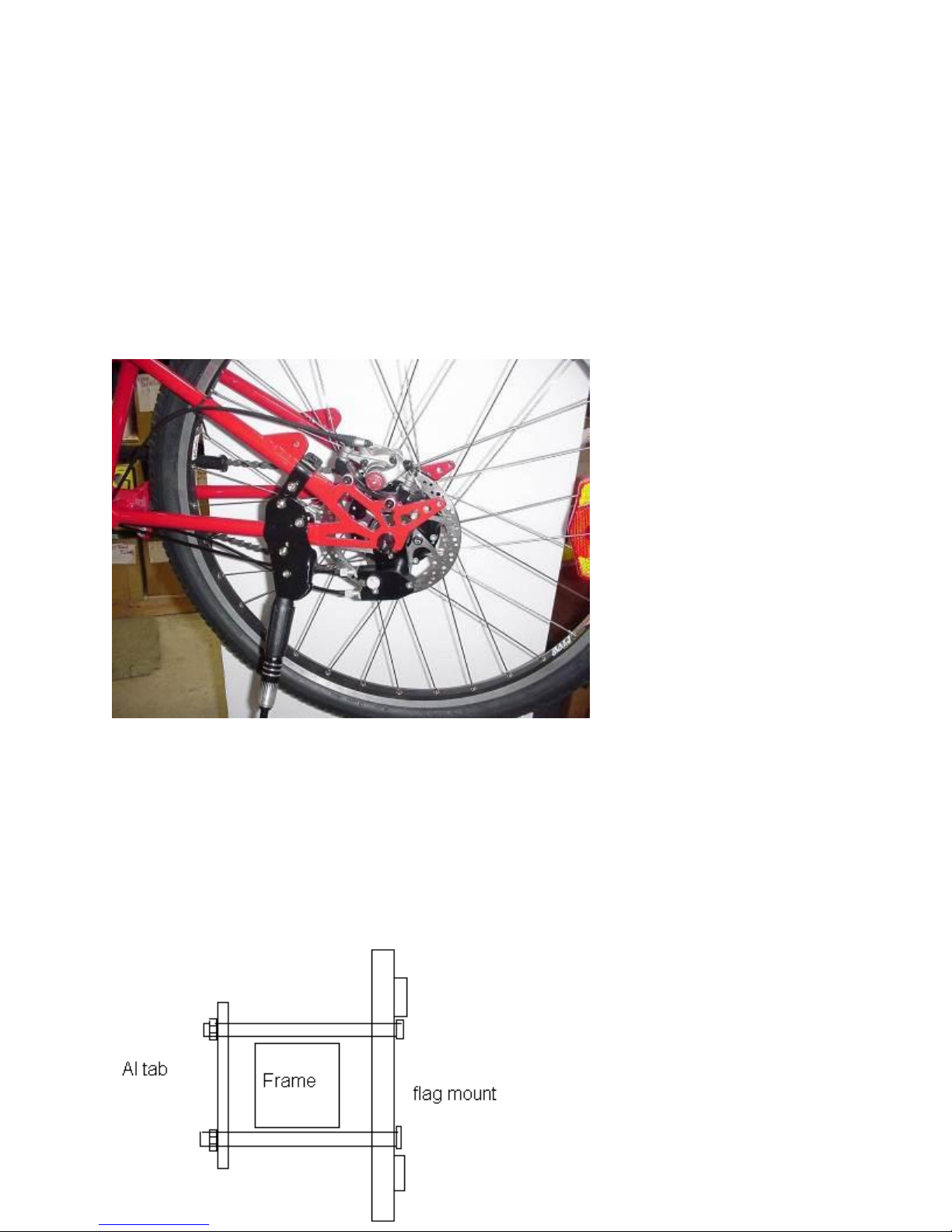
SAFETY FLAG
Place frame protection tape on frame where you want the flag (the left rear side of the frame is
a good visible spot).
Attach the flag mount using the #10 bolts and lock nuts provided. Sandwich the frame between
the flag mount and the flat tab,
straighten and tighten. Do not
over tighten or the mount may
bend making insertion of the
flagpole impossible.
Figure 6.9. Safety Flag mount
Technical Manual 6-6
Page 34

Figure 1. Timing position of the upper and
lower cranks
HANDCRANK ASSEMBLY
Tools needed: Metric hex set: 5mm, 7/16” open end
wrench, ½” open end wrench
Lift out of box TAKE CARE NOT TO CRIMP THE
CABLES OR CABLE HOUSING!
Unwrap lower portion, do not unwrap the crank yet.
Plug lower stem into derailleur tube of trike with chain
tubes on the right. Tighten the derailleur tube collar clamp.
Unwrap and slide fork stem clamp onto fork stem with tab
to left and bolts to the back of the trike. Tighten the
headset down using the headset top cap. Do not tighten
the clamp yet.
Connect the tie rod loosely to the linkage steering tab.
Now you can unwrap the top. MAKE SURE TO PUSH THE
CABLE HOUSING INTO THE BARREL ADJUSTERS ON THE BRAKES
AND SHIFTERS; DON’T CRIMP CABLES!
Here comes the 4-hand part:
Get some strong, mechanical help.
Holding the front wheel in alignment, align the linkage
steering system and tighten the bolts on the linkage
steering tab and fork stem clamp.
Insert the chain into the chain tubes. Loop around foot
crank and pin the chain back together. Check to make sure
the link moves freely.
Align the hand crank and pedals as shown in Figure 1.
Hand crank perpendicular to ground/foot crank
perpendicular to line between cranks. This is the timing
that allows the hand crank to not interfere with your
knees.
Loosen the bolt on the Linkage steering stem tube clamp.
This is tricky. Lift up hard on the hand crank, keeping it in
its vertical position, align with the front fork and have
someone else tighten the collar clamp to hold in place. The
bottom bracket in the center of the hand crank should be
at your shoulder height when everything is tightened in
place.
Attach the large cable tie to the spring, tighten enough to
hold in place but not too much to crimp tube and trim
flush. Figure 2.
When all that is done to your satisfaction, connect the new cables to your brakes and
derailleurs.
Run the housing between the frame and the linkage rod.
Technical Manual 6-7
Page 35

Figure 2. Detail of lower clamp
HEEL PLATES
Install Heel Plates by unbolting or popping rear pedal
reflector off with a flat screwdriver. Bolt heel plate
onto pedal using reflector holes, L opening down.
Place foot on pedal as normal. Slide heel cup up to
heel. Mark the underside with a marker and tighten
the bolts holding the plates together using the mark to
keep the proper length. Some pedals may have 5mm
holes. If so, use 5mm bolts supplied.
Technical Manual 6-8
Page 36

BRAKES
BRAKES
BRAKESBRAKES
Our standard brakes are cable-actuated disc
brakes. Disc brakes have a “burn-in” period
and the braking force gradually increases as
the “burn-in” period progresses. The
calipers and rotors heat up when used. Do
not touch them or try to adjust them when
hot. Be extremely careful with fingers
around rotating brake disks.
We use "linear-pull" or "vee-brakes" on
cycles with internal hubs. The brake arms
are held onto the brake bosses with a
button-cap hex bolt. The brake shoe
Figure 5.1 Cable actuated disc brake
rim when the lever is not being squeezed); these need to be set evenly, so that neither side drags.
These springs are generally adjusted with the small outside screws on most models of brake.
We have included the Avid Brake Manual with your cycle. Please read it and familiarize yourself
with the operating and adjustment instructions. Avid has instructions on adjusting and maintaining
the ball bearing disc brake BB-5 and BB-7 on this web site:
http://www.sram.com/_media/techdocs/2006_BB5and7_English.pdf
PARKING BRAKE
PARKING BRAKE
PARKING BRAKEPARKING BRAKE
Lightfoot trikes have 2 simple parking brake systems. The first is the brake loop; a very simple low
tech braking solution that comes with every cycle. Slip it over the grip, squeeze the brake lever.
Pull the shock cord loop over the brake lever.
The second is a factory add-on option. It is a locking brake lever. If your trike has a parking brake:
squeeze the left (front) brake lever to see a ¼” hole into which the parking brake pin fits snugly.
Use it when you are loading your trike or parking it on sloping ground.
BRAKE HOUSING
BRAKE HOUSING
BRAKE HOUSINGBRAKE HOUSING
On long cable runs, lubricate the cable where it goes through the housing by applying a few drops
of White Lightning or other lubricant. The very long runs create drag that the return springs on
brakes may not be able to easily overcome; lubrication helps brake levers and calipers return to
their fully open position.
ADJUSTING BRAKES
ADJUSTING BRAKES
ADJUSTING BRAKESADJUSTING BRAKES
Disc Brakes
Disc Brakes
Disc Brakes Disc Brakes
• Before each ride: 1) check cables for wear or fraying. 2) Squeeze the brake lever firmly and
check for proper brake function. Adjust for pad wear if necessary. 3) Check pads for wear
and replace if necessary. 4) Make sure the rotors are free of foreign substances and oils.
should be adjusted until the shoe lines up
with the wheel rim. Springs control the
"return" of the brakes (pulling back from the
Technical Manual 5-1
Page 37

• Spring tension adjustment: turn the spring tension adjustment screw with a 2.5 mm hex
wrench. Turning the screw clockwise increases spring tension, which equals a harder lever
pull.
• Cable slack adjustment: use the barrel adjuster on the brake lever to remove cable slack.
Turn the adjuster out until there is no free play in the lever, but not so far that the torque
arm on the caliper is advanced. The torque arm should return completely when the brake
lever is released.
• Pad wear adjustment: turn both inboard and outboard red adjusting knobs clockwise 1 or
2 clicks as needed to restore your brake to optimum settings.
adjuster to compensate f
adjuster to compensate for pad wear.
adjuster to compensate fadjuster to compensate f
or pad wear.
or pad wear.or pad wear.
DO NOT USE your barrel
DO NOT USE your barrel
DO NOT USE your barrel DO NOT USE your barrel
• Pad Wear: a pad should be replaced when its total thickness is less than 3 mm. To remove
the pads, back both red adjuster knobs all the way out (counter clockwise) then squeeze
the pad tabs together and pull both pads straight out of the caliper. Reverse the process
for installation of the new pads. Squeeze the brake pad/spring clip assembly together then
press firmly into the caliper until it clicks into place.
• Care and cleaning: Extreme care must be taken when cleaning both the cycle and the disc
brakes. Under normal use the pads and caliper rotor will not need to be cleaned. If
necessary, use only water and dish detergent. Be sure to thoroughly rinse all soap residues
from the rotor. Dry with a clean paper towel.
BALANCING BRAKE PAIR
BALANCING BRAKE PAIRSSSS
BALANCING BRAKE PAIRBALANCING BRAKE PAIR
All
All----wheel braking
wheel braking on three-wheelers or four-wheelers requires not only that each brake be
AllAll
wheel brakingwheel braking
symmetrically adjusted, but that each front or rear opposite pair is balanced. Both left and right
pairs that are controlled by a single brake lever should have approximately equal amount of spring
tension so that each pulls back from the rim in equal amount when that brake lever is released.
Figure 5.2. Trike brake cable arrangement
as hard as possible (under full braking) without the brake lever contacting the handlebar. As well,
the brake lever should move only a little (as your hand tightens upon it) before the brake begins to
activate.
Technical Manual 5-2
When brakes are adjusted properly, you
should be able to squeeze the brake lever
Page 38

RIDING YOUR CYCLE
RIDING YOUR CYCLE
RIDING YOUR CYCLERIDING YOUR CYCLE
Any of our cycles will feel odd to the first-time recumbent rider. Two-wheel models will seem
hard to balance at first, and clumsy to push or move around. Trikes and trucks will seem strange in
every respect. If you are a long-time upright bike rider, it may even be worse than if you haven't
ridden in 10 years. Have patience. With practice almost anyone will be able to ride straight and
efficiently and turn predictably. Pushing and maneuvering the bike will become second nature.
However, it may take some time.
When learning to ride a recumbent two-wheeler, begin in a level, paved parking lot, with lots of
room to maneuver and no traffic. Do not begin on a crowded street, or on gravel, or on a hill. Do
not use toe clips on your firs
not use toe clips on your first ride.
not use toe clips on your firsnot use toe clips on your firs
to ride slow. Start in a medium-low gear. Some people will have their balance in 20 seconds;
some will take 20 minutes.
TTTThree secrets to learning to ride a recumbent:
hree secrets to learning to ride a recumbent:
hree secrets to learning to ride a recumbent:hree secrets to learning to ride a recumbent:
1. Start with a power stroke (pedal straight up)
2. Lean back into the seat
3. Relax your arms when you ride.
Many of our vehicles use "tiller" steering. Practice swinging the handlebars back and forth to get a
feel for the motion of steering, and practice on level terrain before you steer down a hill and
around a corner.
SMOOTH SHIFTING
SMOOTH SHIFTING
SMOOTH SHIFTINGSMOOTH SHIFTING
Derailleur systems require that the rear wheel and pedals be turning when you shift. Also, you
must ease off on the pressure to the pedals as you shift. Index shifters must be adjusted
or they will not shift consistently and may not stay in gear.
or they will not shift consistently and may not stay in gear. If you cannot get your gears to shift
or they will not shift consistently and may not stay in gear.or they will not shift consistently and may not stay in gear.
consistently using the information printed in this owner's manual, have an experienced bike
mechanic help on this critical adjustment.
The wheel and pedals do NOT need to be turning when you shift an internal hub. The internal
hub systems can also shift under pressure; however, it will shift better and the internal components
will last longer if you ease off when shifting.
EFFECTIVE BRAKING
EFFECTIVE BRAKING
EFFECTIVE BRAKINGEFFECTIVE BRAKING
When braking a two-wheeler, keep in mind which lever controls the rear brake; it is almost always
the lever on the right. Use the rear brake for most of your braking. On gravel, snow, or slick
surfaces, use the rear brake and be cautious with using the front brake. If the front locks up, you
will loose your ability to steer. Experienced riders can skid the rear wheel in gravel without loosing
control.
On dry pavement, use the front brake strongly, in combination with the rear brake for fast stops.
USING
USING A MIRROR
USINGUSING
If your cycle did not come with a mirror, or if you do not have a good helmet mirror, get a mirror.
Immediately. You will be, and will feel, much safer.
A MIRROR
A MIRRORA MIRROR
Do not begin on a crowded street, or on gravel, or on a hill. Do
Do not begin on a crowded street, or on gravel, or on a hill. Do Do not begin on a crowded street, or on gravel, or on a hill. Do
t ride. A little bit of speed will help your balance on a bike; don’t try
t ride. t ride.
Index shifters must be adjusted correctly,
Index shifters must be adjusted Index shifters must be adjusted
correctly,
correctly, correctly,
Technical Manual 7-1
Page 39

Learn to use the mirror without turning your head. Make frequent checks of overtaking traffic by
glancing at the mirror, moving only your eyes. Don't stare at it, just check and go. This
continuously updated consciousness of what is behind you will make you much safer if you should
need to make an emergency maneuver.
If you are unavoidably on a narrow street with high-speed traffic and no shoulder; use the mirror
to check on overtaking vehicles as you see or hear them coming up behind you. You may spend
more time looking in the mirror than looking ahead of you, since the greatest threat to your safety
on such a street is from overtaking vehicles. If the overtaking vehicle is not getting over, you may
decide to hit the ditch. Do not passively hope that everyone will watch out for you on a shoulderless road; some may not see you, especially if they are tailgating another overtaking vehicle.
A Mirrycle ™ is a good choice; other handlebar-end mirrors may work well. Pedicabs or tall-box
cargo vehicles may need a handlebar extension (such as those cow horn looking-things that bolt
on the end of mountain bike bars) to elevate the handlebar-mounted mirror.
COMFORT, CADENCE AND
COMFORT, CADENCE AND POSITION
COMFORT, CADENCE ANDCOMFORT, CADENCE AND
POSITION
POSITIONPOSITION
The most likely complaint about the recumbent position will be about knee soreness. This
complaint will come from those who push too hard on the pedals at low rpm's or have the seat
adjusted too far forward.
On a recumbent, you can’t stand up to protect your knees if in too high of a gear, like you can on
an upright bike. So, don't mash on the pedals. Spin. Try to keep your pedaling cadence above
70-80 r.p.m. This may seem very fast, but it works to sustain your energy and protect your knees.
Long distance riding may be most efficient and sustainable at 90-100 r.p.m.
If you are stuck in a high gear when stopped on a hill or when starting a heavy load, pedal slowly
and gently until you have an opportunity to shift down to a gear that you can spin at a 90 r.p.m.
cadence. Pedicab drivers take note: a few days of heaving on the pedals in a recumbent position
can put you in pain and temporarily out of commission.
Your knees should almost straighten out as you pedal forward. Adjust the seat until they feel
comfortable. It has been said that if the front of your knee hurts, you are pushing too hard with
your seat too close to the pedals; if the back of your knee hurts, you are pushing too hard with
your seat too far back.
Use your ankles; don't lock the feet in one position. Try to use your toes to push and pull the
pedal around its orbit. Use toe clips or "clip-less pedals" to help your ankle motion and to keep
your feet securely on the pedal. Clip-less pedals and matching shoes with cleats are necessary to
efficiently ride bike or trike models with a high bottom bracket position; they reduce the constant
effort of trying to keep your feet on the pedals.
Shoulders can become tense and tight if your seat is not adjusted correctly. Try putting your
weight onto the seat back, and consciously loosening your grip on the handlebars. If your
handlebar simply will not adjust back far enough or high enough for you, we can supply lengthened
custom handlebar stems.
Technical Manual 7-2
Page 40

Our mesh seat has an oversized pocket for the foam pad that allows additional padding if you wish
it. If you want additional lumbar or shoulder support, moveable strap-on pads are available from
LFC.
ST
STABILITY
ABILITY
STST
ABILITYABILITY
Our trikes CAN tip over
Our trikes CAN tip over. Practice in a level parking lot to learn their limits. It is fairly easy to put
Our trikes CAN tip overOur trikes CAN tip over
the trike up on two wheels by turning sharply with some speed. If you get a wheel up, bring it
back down by steering back in your original direction of travel. After you have the feel for the
limits of stability of the trike, you will be able to anticipate the need to lean into sharp, fast corners.
When cargo trikes are loaded, they will be more stable than when unloaded.
Enjoy your Lightfo
Enjoy your Lightfoot!
Enjoy your LightfoEnjoy your Lightfo
Remember
Remember four tips for
Remember Remember
3. Relax your arms when you ride!
3. Relax your arms when you ride!
3. Relax your arms when you ride!3. Relax your arms when you ride!
4. Look where you WANT to go!
4. Look where you WANT to go!
4. Look where you WANT to go!4. Look where you WANT to go!
four tips for riding a recumbent:
four tips for four tips for
1. Start with a power stroke
1. Start with a power stroke
1. Start with a power stroke1. Start with a power stroke
2. Lean back into the seat
2. Lean back into the seat
2. Lean back into the seat2. Lean back into the seat
ot!
ot!ot!
riding a recumbent:
riding a recumbent:riding a recumbent:
Technical Manual 7-3
Page 41

HOW TO RIDE SAFELY O
HOW TO RIDE SAFELY ON THE ROAD WITH CARS
HOW TO RIDE SAFELY OHOW TO RIDE SAFELY O
You can greatly reduce your chances of being in a bicycle accident by following some basic rules;
rules which a majority of bicyclists break all too frequently.
COMMONSENSE RULES OF
COMMONSENSE RULES OF THE ROAD
COMMONSENSE RULES OFCOMMONSENSE RULES OF
To avoid the most common accidents in bicycling, follow some simple safety rules:
Rule: You are a vehicle, act like one.
Rule: You are a vehicle, act like one.
Rule: You are a vehicle, act like one.Rule: You are a vehicle, act like one.
Stop at stop signs (failure of bike riders to do so is the #3 cause of urban car/bike accidents).
Go with the flow of traffic (riding against traffic is the #4 cause of car/bike accidents).
Do not ride on the sidewalks.
Do not pass cars (except those in a left turn lane) on the right, unless you have a free lane
or wide shoulder on which to do so.
Rule: The closer your speed is to the speed of automobile
Rule: The closer your speed is to the speed of automobile traffic, the more you should take your
Rule: The closer your speed is to the speed of automobile Rule: The closer your speed is to the speed of automobile
place in traffic.
place in traffic.
place in traffic.place in traffic.
If you are traveling much slower, keep out of the traffic lane--as far to the right as
practicable.
If you are traveling almost as fast, position yourself on the edge of the traffic stream.
If you are traveling as fast as the cars, take your place in the lane.
Do NOT ride fast near the curb.
Do NOT ride closer than 5 feet from parked cars that may open doors in front of you,
forcing you suddenly into traffic.
Do NOT squeeze yourself on to the very margin of the pavement; drivers tend to give you
room in rough proportion to the amount of room you take for yourself.
Rule: Position yourself in an intersection so that it is obvious what your intentions are.
Rule: Position yourself in an intersection so that it is obvious what your intentions are.
Rule: Position yourself in an intersection so that it is obvious what your intentions are.Rule: Position yourself in an intersection so that it is obvious what your intentions are.
If turning right, move toward the right edge of the roadway.
If continuing ahead, stay as close to--or in--the traffic lane as your relative speed allows; this
makes you more visible to drivers coming towards you. This is critical because the #1
cause of urban car/bike crashes is left-turning cars cutting off an on-coming bike. This also
makes you more noticeable to drivers who are waiting to pull out from side streets. This
also is important because the #2 cause of urban car/bike accidents is motorists who fail to
yield at stop signs. Thirdly, this also discourages right-turning motorists from accelerating
past you and cutting you off with a sudden turn.
If you are going straight through an intersection, position yourself to the right edge of the
through lane.
Rule: Act like a car to merge safely wi
Rule: Act like a car to merge safely with slow or moderately fast traffic.
Rule: Act like a car to merge safely wiRule: Act like a car to merge safely wi
Learn to merge
Learn to merge--
Learn to mergeLearn to merge
vehicles do.
vehicles do.
vehicles do.vehicles do.
Do not attempt to negotiate and merge with high-speed traffic.
Rule: Ride a straight line.
Rule: Ride a straight line.
Rule: Ride a straight line.Rule: Ride a straight line.
If you have to leave your path to avoid an obstacle, signal.
Do NOT ride in the parking lane weaving in and out around parked cars.
Rule: Ride at night only with very good lights.
Rule: Ride at night only with very good lights.
Rule: Ride at night only with very good lights.Rule: Ride at night only with very good lights.
Technical Manual 8-1
--look back, assess when it is clear and signal your intentions just as other
----
THE ROAD
THE ROADTHE ROAD
th slow or moderately fast traffic.
th slow or moderately fast traffic.th slow or moderately fast traffic.
look back, assess when it is clear and signal your intentions just as other
look back, assess when it is clear and signal your intentions just as other look back, assess when it is clear and signal your intentions just as other
N THE ROAD WITH CARS
N THE ROAD WITH CARSN THE ROAD WITH CARS
traffic, the more you should take your
traffic, the more you should take your traffic, the more you should take your
Page 42

Do NOT ride on busy narrow high-speed roads at night; only the most radically bright
lighting systems are visible through the confusion of headlights and taillights. Statistically
speaking; at night you are 8 times as likely to have a fatal accident as in daylight.
Ride defensively; assume the automobiles may not see you.
If you plan to ride a night a lot, make your cycle GLOW, using plenty of illumination lights,
clearance lights, blinking tail lights, and reflective materials.
Rule: Ride only on a well
Rule: Ride only on a well----maintained vehicle with fully functional and powerful brakes.
Rule: Ride only on a wellRule: Ride only on a well
Rule: Wear a helmet.
Rule: Wear a helmet.
Rule: Wear a helmet.Rule: Wear a helmet.
maintained vehicle with fully functional and powerful brakes.
maintained vehicle with fully functional and powerful brakes.maintained vehicle with fully functional and powerful brakes.
We, at Lightfoot Cycles, want you to enjoy your cycle for a very long time. If you
have any sort of problem that you or your local bike shop cannot fix, please let
us know.
Have fun;
and remember to
SIT BACK and RELAX
Technical Manual 8-
2
 Loading...