

Page 1
FAN STATUS &
CONTROL
FS
SERIES
Graphic Annunciators * Water Leak Detection
Fireman’s Smoke Control Panels * ARA Systems
109 Portwatch Way Wilmington, N.C. 28412 Phone: (800) 251-2512 Fax: (800) 251-9878
Internet: www.ledinc.com Email: sales@ledinc.com
Features
Non glare protective front
Low power consumption
Ultra Bright Light Emitting Diodes
Lamp Test - Standard
Per Point Diode Isolation on all inputs
Intended for indoor / dry location
Specifications
The Fan Status and Control Annunciator shall
contain all switches, indicators and circuit boards
necessary for a complete and functional system.
Switches and indicators shall be wired to numbered strips to facilitate installation. The annunciator shall be capable of interfacing with addressable fire alarm systems. Lamp Test shall be
provided.
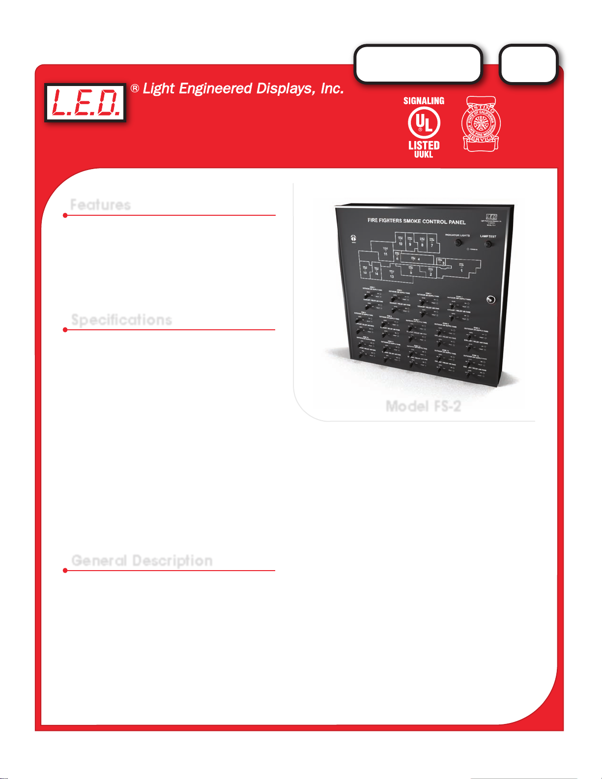
Model FS-2
A
C
L
I
F
F
O
O
R
E
N
T
A
I
A
T
S
S
L
T
A
A
H
T
S
E
R
F
A
I
R
M
E
Switches shall be clearly labeled as to its function. All nomenclature shall be silk screened directly to the
faceplate. The assembly shall be protected by a non-glare acrylic cover, installed in a brushed aluminum frame,
and mounted on a black enamel steel enclosure.
Indicators shall be light emitting diodes. Red will indicate “Fan Off ”. Green will indicate “Fan On”. Indicators
shall be field-replaceable without requiring product disassembly or soldering. Components and wiring shall be
accessable from behind a hinged, key-locked cover. Panel can interface with the FACP or Building Control’s I/O
modules.
The Fan Status and Control Annunciator shall be manufactured by Light Engineered Displays, Inc., or
approved equal.
General Description
The Fan Status and Control Annunciator, FS-Series, is designed for use in high-rise buildings and other facilities that must have a means to manually control the fans or dampers designated for smoke removal during a
fire emergency. The unit is designed to work in conjunction with fire alarm and control systems to provide
visual status and manual control capability for each smoke removal fan.
A three position switch is provided for each fan, along with two status indicators. There “ON/OFF” indicators
are activated by contacts on the fan starter relays. The “ON” indicator will light only when the fan is running. The
“OFF” indicator will light whenever the fan is NOT running.
When the switches are in the “AUTO” position, the system fans will be monitored only. During a fire emergency,
the fire alarm system will operate the fans as per the smoke removal system design. Should conditions
warrant manual control, and at the command of the authority having jurisdiction, the annunciator can be used
to provide specific control of each smoke removal fan.
Page 2
FAN STATUS &
FS
SERIES
CONTROL
Operation
Normal operation is with the panel switches in the “AUTO” position. When the switch is placed in the “ON”
position, the appropriate fan-start relay will be energized. The relay contact will activate the fan. An auxillary
contact will send a signal back to the annunciator as positive indication that the function occurred. When the
switch is placed in the “OFF” position, the corresponding fan-disconnect relay will be energized. The relay
contact will interrupt the automatic fan-start signal from the fire control system.
The FSCS does not control the Smoke Evacuation fans directly. It is the FACP that provides the outputs that
control the fans and lights the Status indicators. Connections from the FSCS to the FACP are through conduit,
20’ or less in length. The switches and the LED indicators in the FSCS are wired to UL Listed terminal blocks
and from the terminal blocks directly to the Fire Control Product outputs.
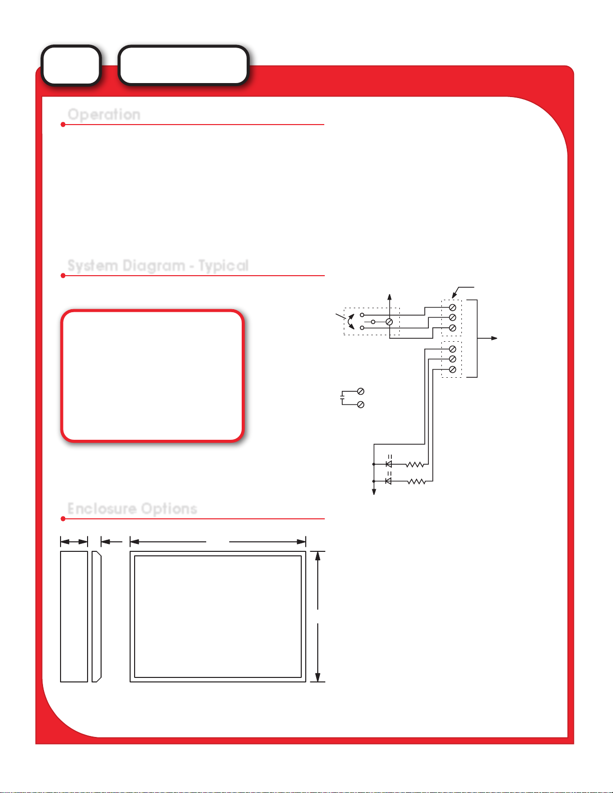
System Diagram - Typical
COMMON FOR ALL
FAN CONTROL SWITCHES
UL LISTED
TERMINAL STRIP IN
BACKBOX FOR FS
SYSTEM COMPONENTS
MODEL
TS-2
TS-3
KS-2
KS-3
RS-2
RS-3
LED
A typical Fan Panel will require one control switch
DESCRIPTION
Two Position Toggle
Three Position Toggle
Two Position Keyswitch
Three Position Keyswitch
Two Position Rotary Switch
Three Position Rotary Switch
On/Off Indicators
and two indicators per fan.
Enclosure Options
4" 7/8"
"W"
AUTO
Polarity and voltage may differ as per individual
fire alarm system requirements.
KEYSWITCH - FOR USE TO
DISABLE / ENABLE THE FAN
CONTROL SWITCHES. TO
BE WIRED AS PER FCP
MODEL
ON
OFF
COMMON FOR FAN
STATUS LED’S
FAN "ON"
FAN "OFF"
WIDTH x HEIGHT
FS-0
"H"
FS-1
FS-2
FS-3
FS-4
9” x 18“
14” x 23 7/8“
23 7/8” x 24 1/2“
23 7/8” x 35”
36” x 48”
FOR CONNECTIONS
TO THE FCP.
TYPICAL OF ONE (1)
SWITCH GROUP TO
CONTROL ONE (1)
FAN STARTER.
FANS
1 - 9
7 - 13
14 - 26
27 - 40
41 - 66
Backbox
For Semi-flush mounting, add 3” to overall “W” and “H” dimensions.
Graphic Door
Consult the factory regarding custom sizes, products, options or special requirements.
NOTE:
Units may be mounted Vertical or Horizontal
 Loading...