

Page 1
www.lightemotion.com.au
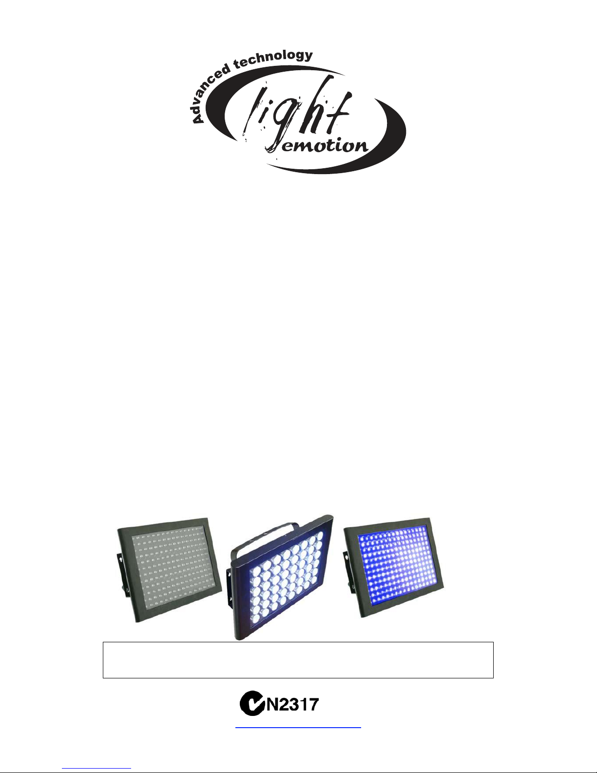
UVLED
5mm – 192 UV LEDs
UVLED1
1W – 48 UV LEDs
LED STROBE
5mm – 192 White LEDs
User’s instruction manual
This manual contains important information about the safe installation and use of this
product. Please read this instruction manual carefully before installing or operating
Please keep these instructions in a safe place for future reference
www.lightemotion.com.au
Page 2

CONTENTS
SECTION Page
INTRODUCTION, UNPACKING 2
FEATURES, INSTALLATION 3
MAINTENANCE & PERIODIC CHECKS 4
CONNECTIONS AND CONTROLS 4
POWER, FUSE 4
DIP SWITCHES, STAND-ALONE 5
MASTER/SLAVE MODE, DMX MODE 6
DMX LEADS, DMX TERMINATORS 7
DMX CHANNEL INFORMATION 7
FAQ, SPECIFICATIONS 8
Please note that as part of our ongoing commitment to continuous
improvement and product development, the specifications in this manual are
subject to change without notice. Whilst every care has been taken in the
preparation of this manual we reserve the right to change specifications in the
course of product improvement.
INTRODUCTION
Congratulations on the purchase of your LED product by Lightemotion
We are confident that you will be satisfied with your purchase.
We have prepared this manual to assist you with the care and operation of
this item.
The lighting effect can be operated in following modes
- Audio activated
- Strobing mode
- Automatic mode
- Stand-alone
- Master/Slave
- DMX
UNPACKING
CAUTION: Do not use sharp objects whilst unpacking this product
Contents of the carton
- 1pc lighting effect
- 1pc Yoke (Hanging adaptor)
- 2pcs Thumbwheels
- 2pcs Rubber washers
- 1pc IEC power lead
Please note: Some of the items above may be fitted to the product by the
manufacturer
2/8
Page 3
FEATURES
• Automatic mode
• Strobing mode
• Audio Activated with sensitivity control
• Master/Slave linkable
• DMX-512 controllable 3 channels
INSTALLATION
CAUTION:
For safe mounting read the following
instructions carefully:
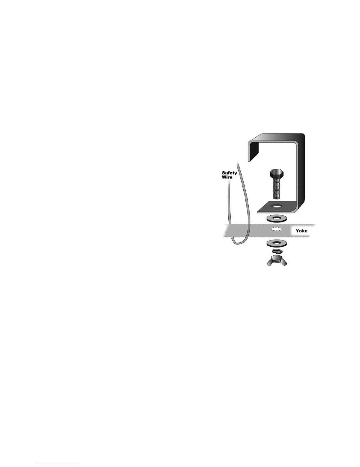
• Use suitable hook clamps* for hanging
the lighting effect
• Use a safety wire* with a breaking
strain of more than double the lighting
effect
• Do not look directly into the light
source
• Make sure the lighting effect has
suitable ventilation as per the
instructions below
• This lighting effect is intended for
indoor use only
• To avoid electrical shock keep away
from rain and moisture
• Keep unit out of reach from children
NOTE:
Use washers* and spring washers* when attaching your hook clamp* to
the yoke
1. For installation of the hook clamps* and safety wire* please refer to Fig
3.
2. This lighting effect must be 0.5m away from any flammable materials or
any walls or ceilings.
3. Do not block or inhibit the air flow from the ventilation vents
Lightemotion have various hook clamps* and safety wires* suitable for your
lighting effect. Please contact your local dealer for more information
*Not included
3/8
Page 4
MAINTENANCE & PERIODIC CHECKS
CAUTION:
Some maintenance and checks may require the product to be opened and
should only be done by qualified persons. Warranty may be void if damage
has been caused by improper maintenance
• Perspex lenses should be wiped with a clean moist cloth to remove
dust and residue
CONNECTIONS AND CONTROLS
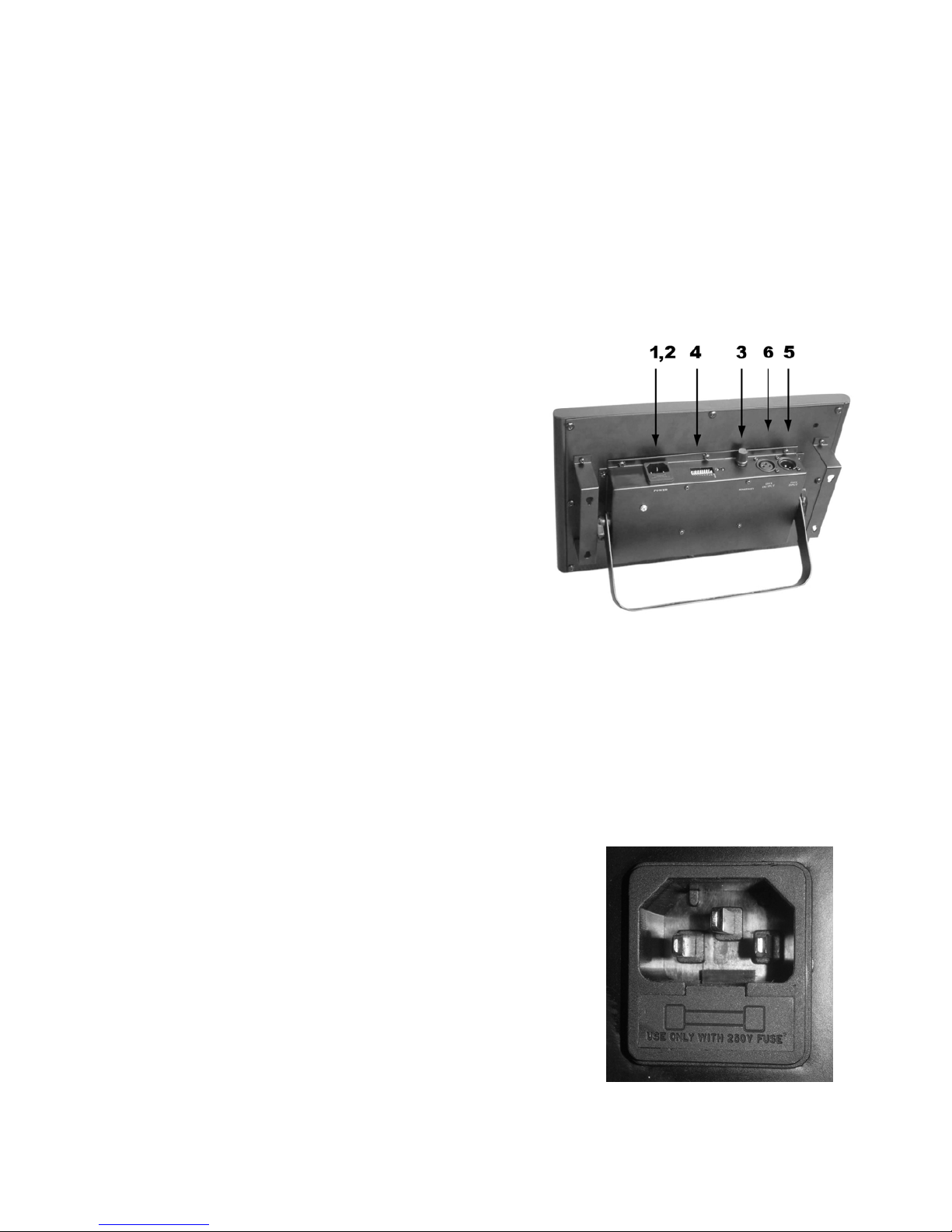
1. Power input
2. Fuse Holder
3. Sound sensitivity pot
4. Dip switches
5. DMX input socket
6. DMX output socket
POWER
CAUTION: This lighting effect is designed to
operate at 240V.
Power Consumption UVLED: 55W
Power Consumption UVLED1: 12W
Power Consumption LEDSTROBE: 12W
FUSE
CAUTION:
Only use the correct fuse as specified on the rear panel of the lighting effect.
Disconnect the lighting effect from the mains before attempting to replace the
fuse
NOTE:
This lighting effect has a position for a spare fuse
located in the fuse holder toward the outside of the
fixture
To replace the fuse please follow the following steps
1. Remove the fuse holder with a screw driver
(Refer to fig 4.)
2. Remove existing fuse
3. Fit new fuse
4. Refit the fuse holder
Fuse: M205 2A fast
4/8
Page 5
DIP SWITCHES
The DIP switches allow the user to change the mode and operation of the
lighting effect by setting the switches to different combinations.
DMX
To determine the starting address for the each lighting effect you should refer
to your DMX controller user manual.
CALCULATING THE STARTING ADDRESS
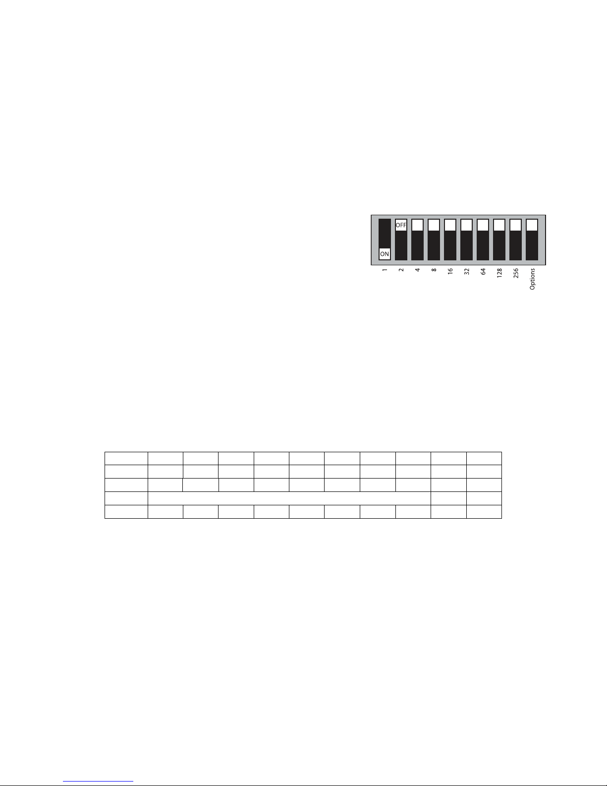
To calculate the starting address you add the
value of all the switches which are ‘ON’ and that
value is the address that is required.
(Refer to Fig 6)
STAND-ALONE
NOTE:
There are multiple stand-alone settings available. Refer to the table below for
more details
SETTINGS
Effect12345678910
Sound 0 0 0 0000000
Auto0000000001
Strobe Strobe speed 0 0
All on0000000010
FOR SOUND ACTIVE PROGRAMS
1. Turn the Sound sensitivity pot (refer to fig 4.) anticlockwise to ‘0’
2. Turn up your music to the volume which will be used throughout the
show
3. Then turn the sound sensitivity pot clockwise till the lighting effect
moves to the sound of the beat
5/8
Page 6
MASTER/SLAVE MODE
CONNECTIONS
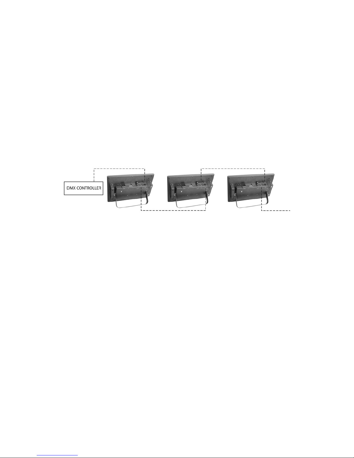
To connect multiple units in Master/Slave mode you need to connect a 3 pin
DMX lead (Refer to Fig 7) from the DMX output socket of the master to the
DMX input socket of the slave, then from the DMX output socket of the first
slave to the DMX input socket of second slave and so on and so forth. (Refer
to Fig 10.)
SETTINGS
You then need to set the unit to Master/Slave mode by flowing these steps
1. Set the first unit to sound or auto mode as per the Stand-Alone
instructions
2. Set the rest of the units to DMX address 1 (refer to DMX mode)
DMX MODE
NOTE:
To determine the address required you should refer to your DMX controller’s
manual
Do not forget to use a DMX terminator at the final output in the chain
Do not forget to turn off the ‘Blackout’ on your controller
CONNECTION
To connect the lighting effect in DMX mode you need to use a 3 pin DMX lead
(Refer to Fig 7) from the DMX output socket of the controller to the DMX input
socket of the first unit, then from the DMX output socket of the first unit to the
DMX input socket of second unit and so on and so forth. (Refer to Fig 10)
SETTINGS
You then need to set each unit’s DIP switches to the addresses required
(REFER to DIP switches section)
6/8
Page 7
DMX LEAD
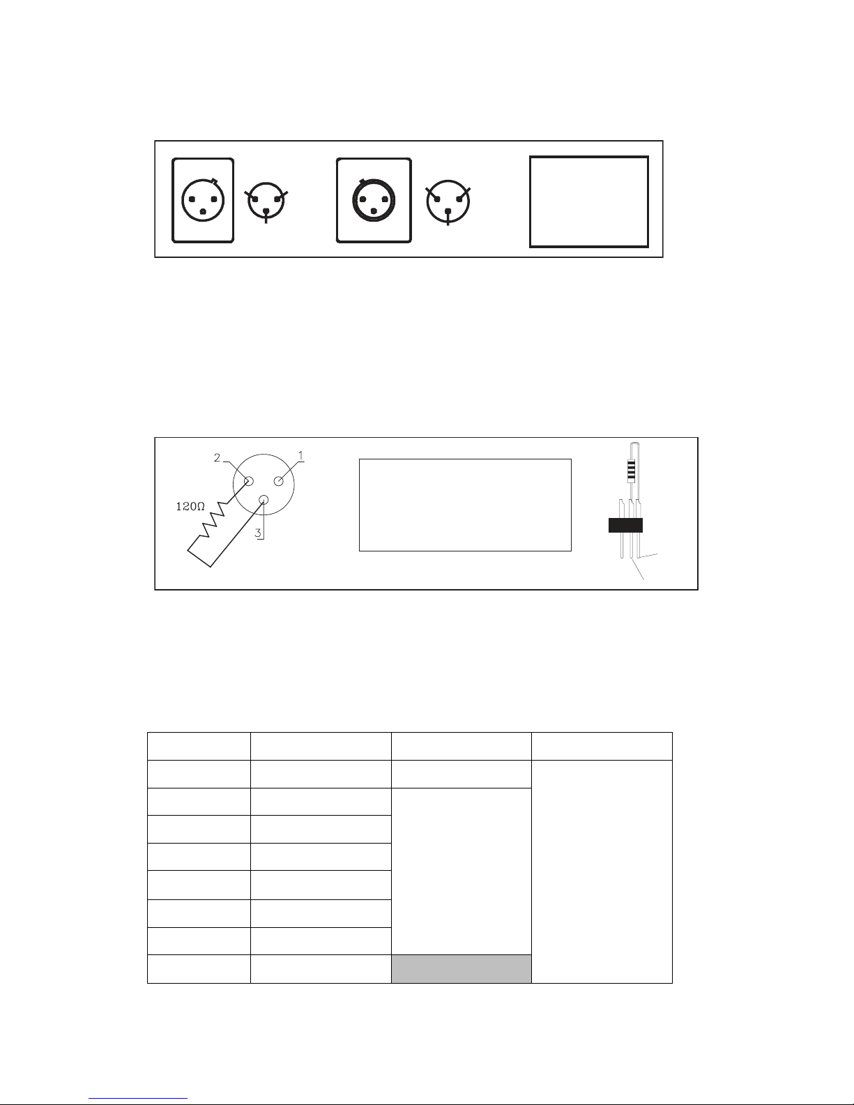
The DMX lead is used to link up multiple units. For Wiring connections refer to
fig 7.
DMX IN
1
2
3
1
2
3
DMX OUT
DMX 512
PIN FUNCTION
1
2
3
GND
DATA DATA +
DMX TERMINATOR
A DMX terminator helps to reduce ‘noise’
on the DMX chain, and makes the light respond
to control more accurately.
It should be plugged in to the last fixture in any chain.
For Terminator connections refer to fig 8
PIN 3
PIN 2
DMX TERMINATOR CONNECTION
Connect a 120? (OHM) resistor across
pins 2 and 3 in an XLR plug and insert
into the DMX OUT socket on the last
unit in the chain.
DMX CHANNEL INFORMATION
The lighting effects use 3 DMX channels as per table 11
Table 11 DMX CHANNEL INFORMATION
Value Channel 1 Channel 2 Channel 3
000 – 029 Dimmer mode Flash Speed
025 – 049 Auto 1
050 - 074 Auto 2
075 - 099 Auto 3
100 - 124 Auto 4
125 - 149 Auto 5
150 - 174 Auto 6
Speed
250 - 255 Sound mode No effect
Intensity
Page 8
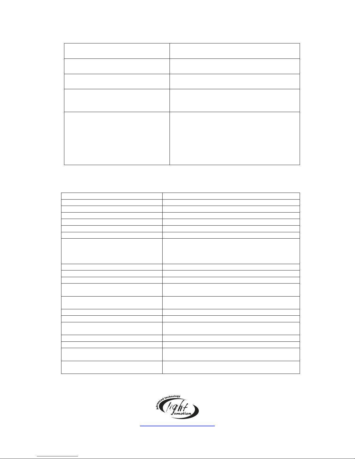
FREQUENT ANSWERED QUESTIONS
Symptom Fault
Unit does not power up Check that the power outlet is turned on
and fuse is intact
Unit powers up but no light
appears
Check that the mode is set correctly and
that you are controlling the unit correctly
Unit chases constantly and not to
the beat of the music
Check that the microphone sensitivity is
not turned up too high and that the mode
is set correctly
Units do not work or is
uncontrollable when linked or in
DMX mode
Check that the mode is set correctly,
check that all the leads are OK, check that
the controller is set to pin 3 positive
(If linking, the lead should come out of the
Master/Slave output socket)
(If using DMX, the lead should come out of
the DMX output socket)
SPECIFICATIONS
Voltage: 240V AC
Power Consumption: UVLED 12W, UVLED : 55W LEDSTROBE: 12W
Operating Frequency: 50Hz
Power lead: Fixed
Fuse: M205 2A fast blow
Sound activated: Yes with sound sensitivity control
Stand alone mode Yes
DMX: 3 channels
Ch1: Dimmer , sound active and auto modes
Ch2: Flash speed and auto speed
Ch3: Dimmer
Linkable Yes
Effects / Control: Dip switches
Colour: UV
Output power / level: UVLED and LEDSTROBE : 192 5mmLEDs
UVLED1: 48 1W LEDs
Input connection: Power: Male IEC
DMX: Male 3 pin XLR
Output connection: DMX: Female 3 pin XLR
Rated lamp life: 50 000 Hrs
Beam angle: UVLEDn and LEDstrobe: 20 degrees
UVLED1: 28 degrees
Hanging Bracket Yes
Colour: Black
Weight: UVLED and LEDStrobe : 2.2Kg
UVLED1: 3.1Kg
Dimensions: UVLED and LEDStrobe: 356 x 248 x 165mm
UVLED1 : 368x241x84mm
www.lightemotion.com.au
8/8
 Loading...