

Light Efficient Design LED-8929-HAZ, LED-8929C-HAZ Installation Instructions Manual
Prior to installation, read the entire instructions
WARNING – Risk of fire or electric shock.
LED Retrofit Kit installation requires
knowledge of luminaires electrical systems.
If not qualified, do not attempt installation.
Contact a qualified electrician.
WARNING – Risk of fire or electric shock.
Install this kit only in the luminaires that
have the construction features and
dimensions shown in the photographs
and/or drawings and where the input
rating of the retrofit kit does not exceed
the input rating of the luminaire.
WARNING – To prevent wiring damage or
abrasion, do not expose wiring to edges of
sheet metal or other sharp objects.
Installation Instructions LED-8929***-HAZ
& LED-8929***C-HAZ
• Make all electrical connection according to
national and local codes.
• Installers should not disconnect existing wires
from lampholder terminals to make new
connections at lampholder terminals. Instead
installers should cut existing lampholder lead
away from the lampholder and make new
electrical connections to lampholder lead
wires by employing applicable connectors.
• This retrofit kit is accepted as a component of
a luminaire where the suitability of the
combination shall be determined by
authorities having jurisdiction.
Luminaire Fittings Reference Table
Luminaire
Fitting
Page Number
GE Lighting Filtr-
Gard®
2
Crouse-Hinds
Champ® VMV
4
Appleton
Mercmaster® III
6
Appleton
Mercmaster® II
8
WARNING – Do not make or alter any open
holes in an enclosure of wiring or electrical
components during kit installation.
1
Included with the kit:
1. LED lamp
2. Label for modified luminaire
3. Instructions
4. Wire connectors (2)
Input Rating:
Voltage: 120-277 VAC or 347VAC for C-HAZ
Frequency: 50/60Hz
Wattage: 24W
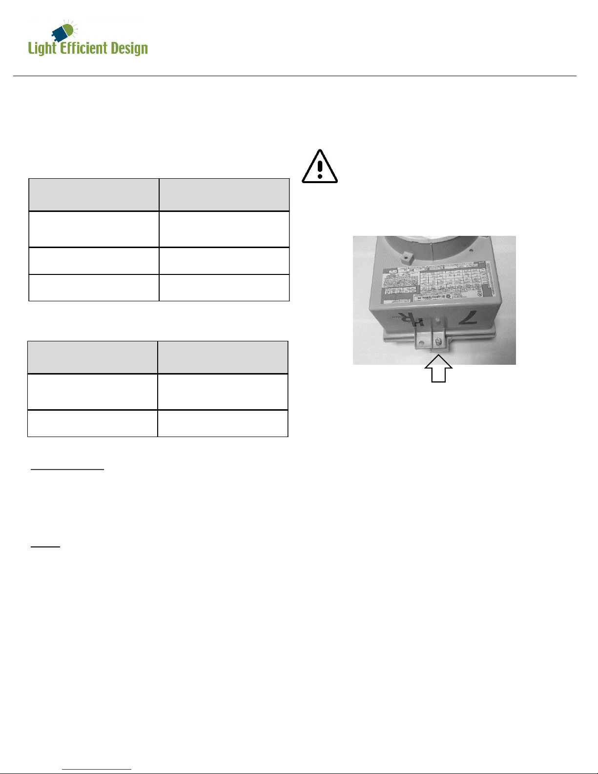
Installation Instructions GE Lighting Filtr-Gard®
LED-8929***-HAZ & LED-8929***C-HAZ
Instructions for retrofitting the following UL
Listed GE Lighting Filtr-Gard® Luminaire
Fitting/Ballast Housing marked for Use in Class
I, Division 2, Groups A, B, C and D Hazardous
Locations
Filtr-Gard® is a register trademark of
General Electric Company
Fitting Filtr-Gard® Catalog #
Ballast Housing Series H2 ballast
housings
Cover/Mounting Series H2000 mounts
Optical Assembly Series H2000 opticals
Tools needed:
1. Slotted screwdriver or wrench to open cover
2. Wire cutter
3. Wire Stripper
Note:
The luminaire does not need to be removed
from the mounting surface prior to
modification.
Retrofit Kit Selection Table
Ballast Housing Retrofit Kit
H2*05K, H2*05L,
H2*10M
LED-8929E**-HAZ
All Others LED-8929M**-HAZ
2
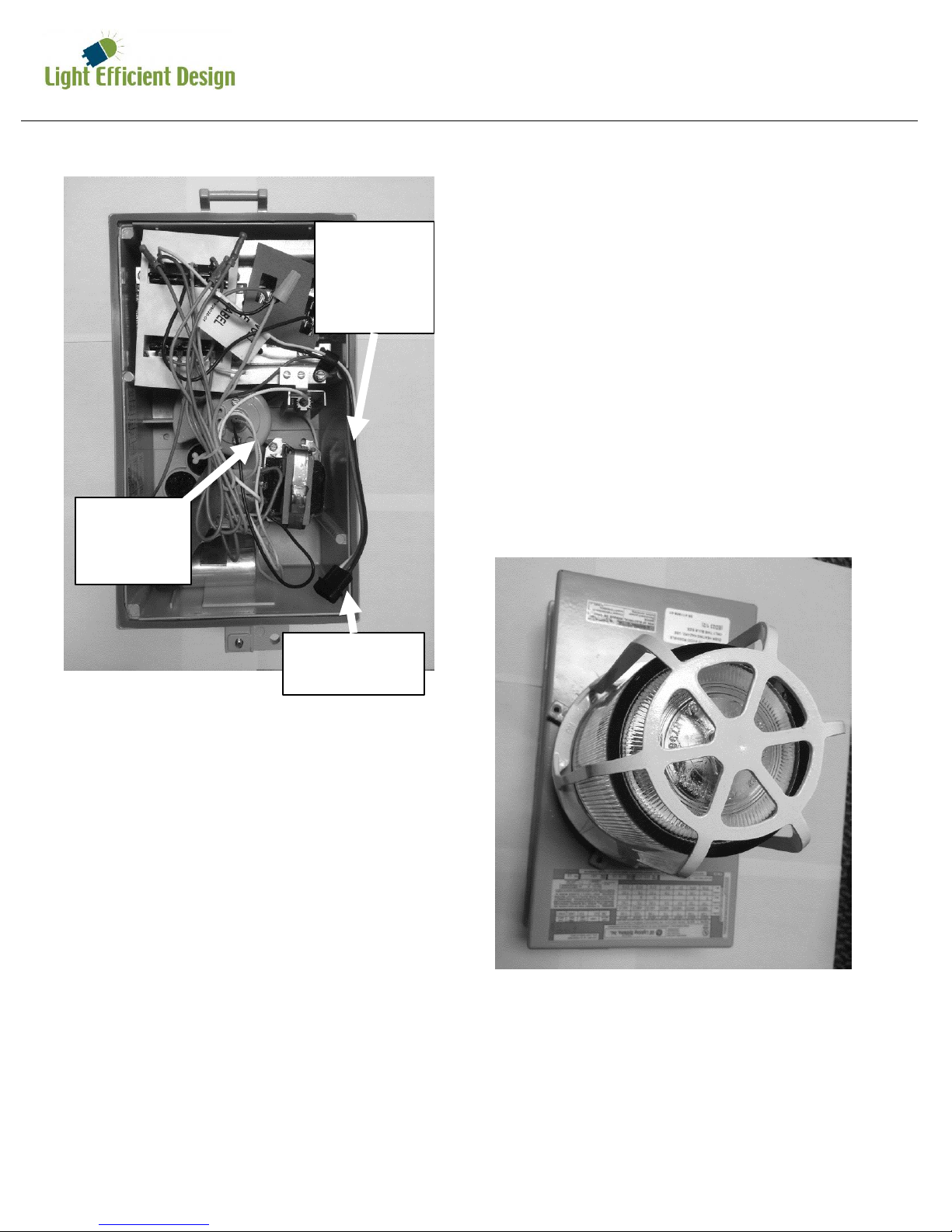
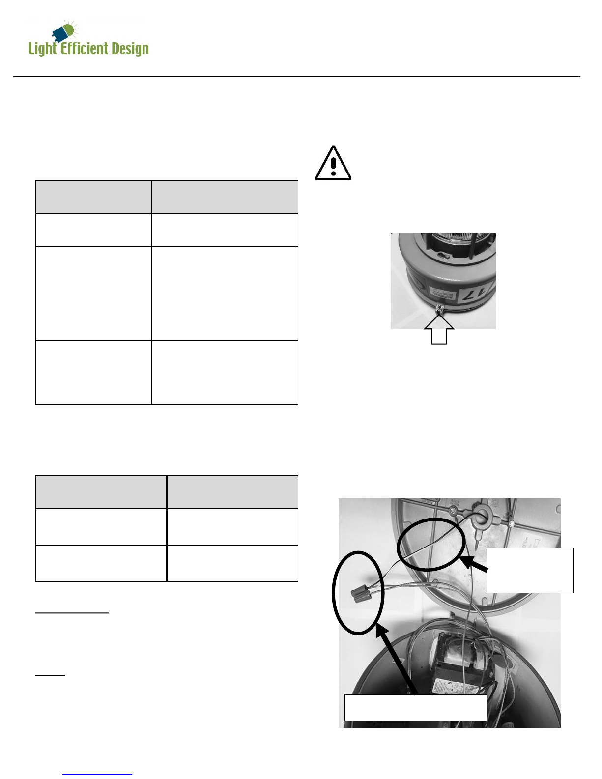
1. Disconnect electrical power to the luminaire at
the supply source
CAUTION – Risk of burn, allow luminaire
and lamp to cool before proceeding
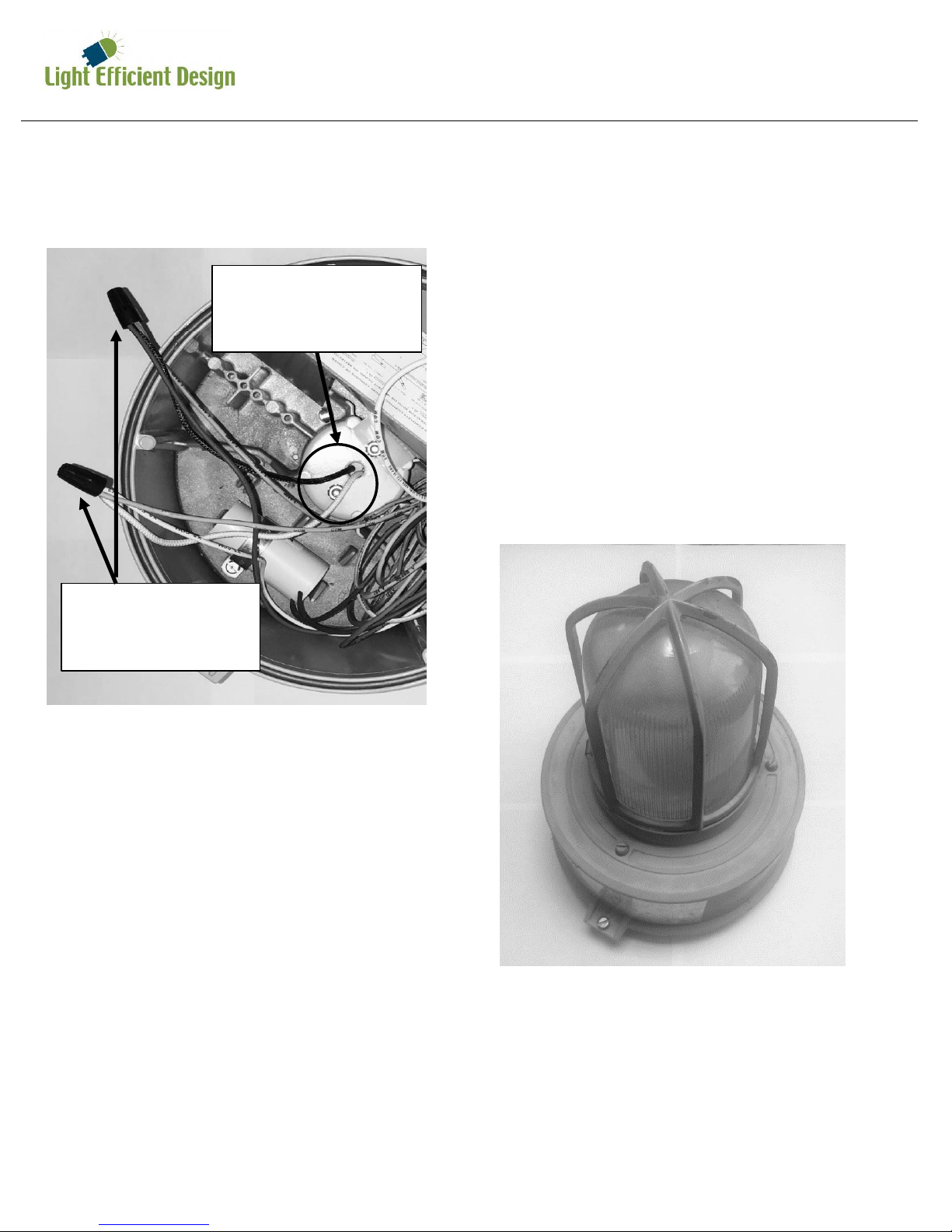
3. Allow the ballast cover to hinge open and
disconnect the quick disconnect between the
cover and housing by pulling the two black
plastic connectors apart.
4. Cut the black and white wires from the quick
disconnect to the ballast circuitry leaving as
much wire to the quick disconnect as possible.
Be careful to leave the green ground wire
connected.
5. Cut the white (neutral) and colored (hot) wires
from the lamp holder in the center of the
ballast housing leaving as much wire to the
lamp holder as possible.
6. Strip 3/8 inch from the incoming quick
disconnect wires from step four and the lamp
holder wires from step five. Using the
included wire connectors to connect white to
white and black to colored (may be black).
Wiring
2. Open luminaire by loosening the screw that
holds the ballast housing and cover together
Light Efficient Design
Tel: (847) 380-3540
www.led-llc.com
sales@led-llc.com
7. Place the ballast housing hinge pin over the
cover hinge. Mate the quick disconnect
connectors between the ballast housing and
cover. Close and secure the ballast housing
and cover by tightening the screw.
Incoming
quick
disconnect
wires
Lamp
holder
wires
Installation Instructions GE Lighting Filtr-Gard®
LED-8929***-HAZ & LED-8929***C-HAZ
Quick
disconnect
3
Lamp Installation
8. Remove the optical assembly covering the
lamp such as guards, globes or reflectors by
un-threading.
9. Remove old lamp
10. Firmly tighten LED lamp enough to depress the
center contact of the lamp holder.
11. Replace the optical assembly by threading into
the ballast housing.
12. Apply the silver adhesive label over the
current label on the luminaire which specifies
the replacement lamp and where it will be
visible during re-lamping.
13. Connect electrical power to the luminaire at
the supply source
Example Globe and Guard
Installation Instructions Crouse-Hinds Champ® VMV
LED-8929***-HAZ & LED-8929***C-HAZ
Instructions for retrofitting the following UL
Listed Crouse-Hinds Champ® VMV Series HID
Luminaire Fitting/Ballast Housing marked for
Use in Class I, Division 2, Groups A, B, C and D
Hazardous Locations
Fitting Champ® Catalog #
Ballast Housing VMVS & VMVM
Champ Cover
(Mounting Module)
APM2, APM3, HPM2,
CM2, CM3, TWM2,
TWM3, JM5, PM5,
QM25
Optical & Guard
components
G24, G24 S808, P21,
RD70, RA70, G241,
G243, G245, P241,
R2, R3, R5, P23, PR2,
PR3, PR5
Tools needed:
1. Slotted screwdriver
Note:
The luminaire does not need to be removed
from the mounting surface prior to
modification.
Retrofit Kit Selection Table
Ballast Housing Retrofit Kit
VMVS050, VMVM070,
VMVM100
LED-8929E**-HAZ
LED-8929E**C-HAZ
All Others LED-8929M**-HAZ
LED-8929M**C-HAZ
Champ® is a register trademark of
Eaton’s Crouse-Hinds
4
1. Disconnect electrical power to the luminaire at
the supply source
CAUTION – Risk of burn, allow luminaire
and lamp to cool before proceeding
3. Allow the ballast cover to hinge open.
4. Remove the wire connectors from the
incoming wires to the ballast circuitry. Be
careful to leave the green ground wire
connected.
2. Open luminaire by loosening the screw that
holds the ballast housing and cover together
INCOMING
WIRES
WIRE
CONNECTORS
Light Efficient Design
Tel: (847) 380-3540
www.led-llc.com
sales@led-llc.com
LAMP HOLDER
WIRES
WIRE
CONNECTORS
Installation Instructions Crouse-Hinds Champ® VMV
LED-8929***-HAZ & LED-8929***C-HAZ
5
Lamp Installation
9. Remove the optical assembly covering the
lamp such as guards, globes or external
reflectors by un-threading.
10. Remove old lamp
11. Firmly tighten LED lamp enough to depress the
center contact of the lamp holder.
12. Replace the optical assembly by threading into
the ballast housing.
13. Apply the silver adhesive label over the
current label on the luminaire which specifies
the replacement lamp and where it will be
visible during re-lamping.
14. Re-connect electrical power to the luminaire
at the supply source
Example Globe and Guard
5. Remove the wire connectors from the lamp
holder wires.
6. Using the included wire connectors connect
the lamp holder wires to incoming wires.
7. Cap off the unused wires with the wire
connectors removed earlier.
8. Place the ballast housing hinge pin over the
cover hinge. Close and secure the ballast
housing and cover by tightening the screw.
Installation Instructions Appleton Mercmaster® III
LED-8929***-HAZ & LED-8929***C-HAZ
Instructions for retrofitting the following UL
Listed Appleton Mercmaster™ III Series HID
Luminaire Fitting/Ballast Housing marked for
Use in Class I, Division 2, Groups A, B, C and D
Hazardous Locations
Fitting Mercmaster® III Catalog #
Ballast Housing MLBG, MLBR, KPB & KPBR
Mounting Hood KPA75, KPA100, KPAF75,
KPAF100, KPC75, KPC100,
KPCH75, KPCH100,
KPS125, KPS150, KPST125,
KPST150, KPWB75,
KPWB100
Optical & Guard
components
CMR-4AN, CMR-4ST, KR2AN, KR2-ST, KRG2, KGU2,
LPG-R*, LPRF-*CP, VPGL*HR
Tools needed:
1. Slotted screwdriver
2. Adjustable wrench
Note:
The luminaire does not need to be removed
from the mounting surface prior to
modification.
Retrofit Kit Selection Table
Ballast Housing Retrofit Kit
MLBG & MLBR LED-8929E**-HAZ
LED-8929E**C-HAZ
KPB & KPBR LED-8929M**-HAZ
LED-8929M**C-HAZ
Mercmaster® is a registered trademark of
Appleton Grp LLC
6
1. Disconnect electrical power to the luminaire at
the supply source
CAUTION – Risk of burn, allow luminaire
and lamp to cool before proceeding
3. Allow the ballast cover to hinge open.
4. Remove the wire connectors/wire nuts from
the incoming wires (wires that supply power
from the conduit system) to the ballast
circuitry. If the luminaire is provided with a
fuse and fuse holder installed to the mounting
hood the incoming wire connected to the fuse
will need to be disconnected here to bypass
the fuse. Discard all the fuses. Be careful to
leave the green ground wire connected.
Wiring
2. Open luminaire by loosening the nut that
holds the ballast housing and cover together
WIRE CONNECTORS
INCOMING
WIRES
 Loading...