

Page 1
Lighted Piston Controller and MIDI Encoder
1
The LPC-1 is a self contained circuit card that will accept up to twelve piston functions and drive up to twelve piston lamps.
Each card will generate midi ON/OFF note for each piston as well as receive midi for clearing the pistons. The LPC-1 can be
configured for either GENERAL Pistons or DIVISION Pistons. MIDI Channel selection and MIDI Note Range are done through
simple DIP Switch selection, no configuration files to write or computer programming, simple setup in Hauptwerk.
FEATURES
Up to 12 piston, each sends a midi note to Hauptwerk.
Up to 12 Piston Lamps, controlled by the LPC-1.
Input voltage ranging from 8 to 15 VDC.
Current Requirement, excluding the type of Lamps, 10ma.
MIDI INPUT and MIDI OUTPUT Jacks with MIDI Through.
On board Crystal Controlled Central Processor Unit.
MIDI Channel set with simple DIP Switch setting.
MIDI Note Range set with DIP Switch setting.
Easy Interface with Hauptwerk.
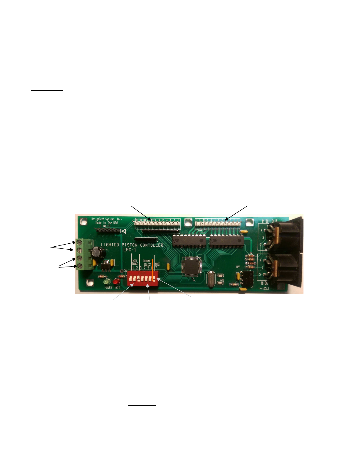
LPC-1
Input, Output, Power Connections and Switch Location.
Switch Inputs, switch to Ground Lamp Or LED Outputs, Pull to Ground
DC Regulated
power supply
ground
DC regulated
power supply Plus
Midi Note Range Select Midi Channel Select
Installation.
Before installing the cards, do a visual check to check for bent pins or other possible damage that may have occurred during
shipping.
Mounting the cards, select a suitable location in the console what will allow for easy access to the pistons. The cards can be
mounted with #4 screws to a back board.
Power Supply and Connections. A 12VDC, 2 amp regulated supply is suitable for proper operation. The card has a Green
Power Connection block with two terminals for the PLUS leads and two terminals for the GROUND leads. See Page 4 for
power supply connections.
Piston Connections. For DEVISION Piston, a card should be used for each manual. For proper operation of Division Pistons, pistons from more than one manual CAN NOT be connected to a single card. Each piston has two switch leads, one of
which connects to one of the twelve PISTON Switch Input. The other lead of each piston should be connected to a common
buss wire that runs from piston to piston. The Common Buss lead should be connected to a COMMON GROUND that is returned to the GROUND terminal of the Green power block.
MODE Select.
MIDI OUT
MIDI IN
1
Page 2
2
General Pistons, Unlike Division piston, the General piston can be wired to more than one manual. Generally there are five
General Pistons per manual, which means that five General pistons from two manuals can be wired to the same card.
Piston Lamps. Either LED or Incandescent lamps can be connected the Lamp Driver outputs. There are twelve Lamp outputs that correspond to the twelve piston inputs. The lamp from the piston switch that is connected to Input One, should be
connected to Lamp Output ONE. The Common side of the lamps or LED’s should be returned back to the PLUS VDC input.
NOTE, Some pistons have 5 vdc lamps, the lamp common should then be connected to a 5 Volt DC supply.
After the wiring is completed and checked for shorts, the piston and lamps can be checked for operation. Turn on the DC
power supply to the LPC-1 cards. Pushing and releasing a piston should cause the piston’s lamp to light. Pushing another
piston connected to the same card should cause the first piston lamp to go out and the new piston’s lamp to turn on. Repeat
the process for all the General and Division piston and lamps.
MIDI Cables, refer to page 4 for information regarding connecting the MIDI Cable. The cards MIDI IN/OUT jacks should
be daisy chained to ensure proper operation. Due to MIDI Input and MIDI output cables, a multi port MIDI to USB interface
should be considered with the IPC–1 in and out going to one set of Input and Output midi jack on the interface and the
manuals, stops and pedals midi lines to other ports. A MIDI to USB interface such as the MOTO 5x5 Micro Lite is a good
example for this type of configuration.
This needs to be done before connecting to the computer.
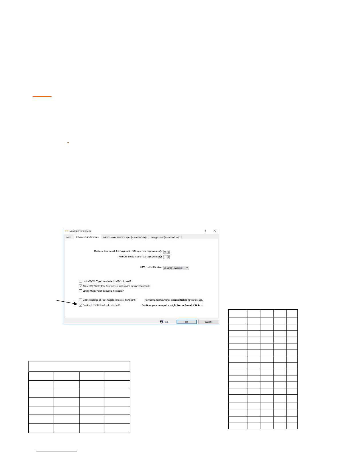
Due to the fact that midi data is being sent from the cards to Hauptwerk and Hauptwerk is sending data to the cards, a
Hauptwerk option needs to be first set. After loading Hauptwerk, from the MENU Bar at the top, select the following.
General Settings/ General Preferences/ Advanced Preferences. Located at the bottom of page, “Don’t halt if MIDI feedback detected?” with a check box will be found. Add a Check Mark to the box.
Click OK, connect the midi cables to the MIDI to USB interface and proceed to load the organ.
Check this box
DIP SWITCH SETTINGS. There are three groups of switches that need to be set.
Switches 1 and 2 are for the MIDI NOTE range.
Switches 3,4,5 and 6 for the MIDI CHANNEL
Switch 7 for MODE. Switch 7 should be set to ON.
MIDI NOTE RANGE SELECT
RANGE SW 2 SW 1
0-11
12-23 X
24-35 X
36-47 X X
Channel Sw 6 Sw 5 Sw 4 Sw 3
1
2 X
3 X
4 X X
5 X
6 X X
7 X X
8 X X X
9 X
10 X X
11 X X
12 X X X
13 X X
14 X X X
15 X X X
16 X X X X
1 2 4 8
2
Page 3

3
For MIDI Channel, select an unused channel or channels. Up to four cards can be set to a single channel with a different
MIDI NOTE Range for each card. Refer to the MIDI NOTE RANGE and MIDI CHANNEL charts for switch selection.
The X indicates the switch is set to the ON position.
Switch in the ON position.
Detecting Pistons. There is a minor difference in the procedure for detecting Division Pistons and General Pistons.
DIVISION PISTONS. Select a Division piston, for example GREAT #1 piston on the screen and with the mouse, Right
Click and select Auto Detect. On the organ console, push the Great #1 piston and DONE should light on the screen, click on
DONE. Repeat the procedure for each Division piston on each manual.
GENERAL PISTONS. This is a two step process, first right click on a screen General piston, select Auto Detect and push
the corresponding console General Piston. Done should light, click on Done.
Step 2, right click on the same screen General Piston and select “Adjust MIDI Trigger Setting”. The following screen will
open. Select the Primary output tab and change the following.
1. Output: to MIDI note on/off
2. MIDI OUT All enabled ports
3. MIDI Channel, and be any channel
4. Note: change to 127.
5. Click the OK button.
What this does is when a General piston is pushed, it will cancel all the Division pistons that were set before a General piston
was pushed.
CANCEL PISTON. For the Cancel Piston, follow steps
1 and 2, the same sequence as with the General pistons.
Set the OUTPUT to MIDI NOTE 127.
3
Page 4

4
Plus 5 to 12 VDC
Division Pistons
MIDI OUT to computer
Division Pistons
Pistons
LPC-1
GND
General Pistons
Connect Black
to Neg or GND
Terminal
General Pistons
MIDI INPUT from computer
Connect the RED to
POSITIVE Terminal.
4
Page 5

5
5
 Loading...